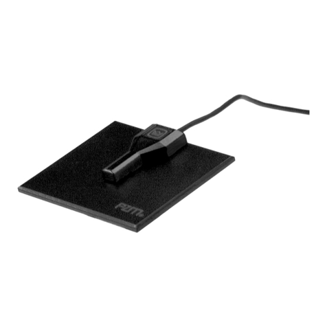
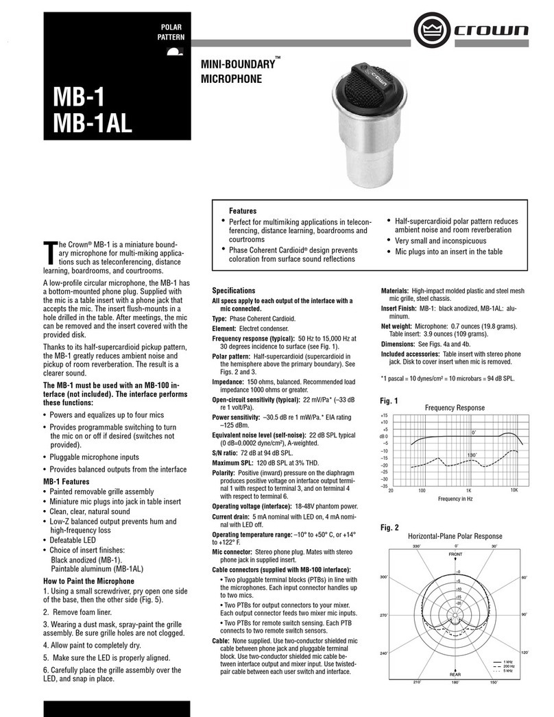
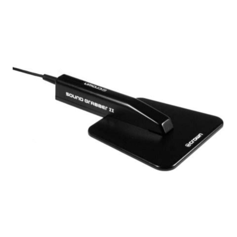
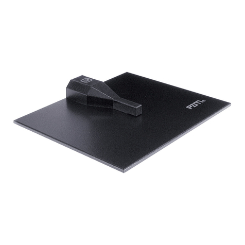
Crown PZM-11 User manual

@crown®
PRESSURE
ZONE
MICROPHONE®
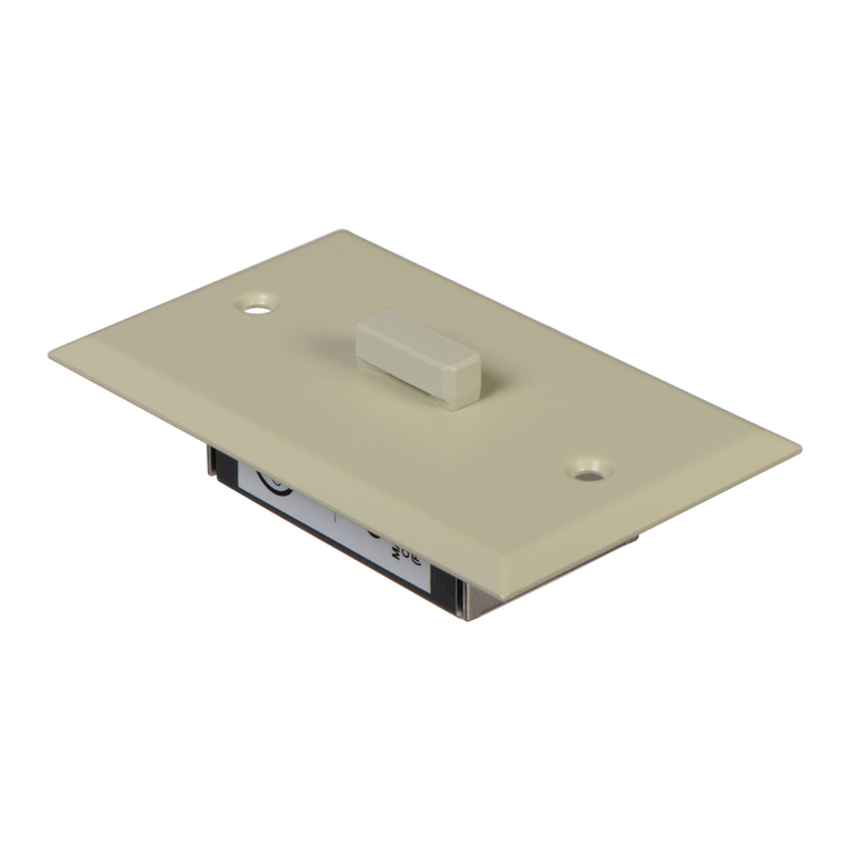
The PZM®-11LL is a Pressure Zone
Microphone®designed for security and
surveillance applications. It is designed to
look like a light switch, not a microphone, so
as not to draw attention.
The PZM-11LL looks and sounds like the
PZM-11, but has a line-level output and is pow-
ered by 24V AC, 12-24V DC, or phantom power.
Since the PZM-11LL has a high output, it can be
plugged directly into a VCR line input—no costly
mic preamp is needed.
The mic can be mounted in the ceiling or wall in
a standard electrical outlet box. It also can be
installed without a box because its electronics
are shielded inside a removable metal housing.
Like other Pressure Zone Microphones, the
PZM-11LL uses a miniature mic capsule
mounted very near a sound-reflecting plate or
boundary, in the Pressure Zone. In this zone,
direct sound from the sound source combines in
phase at all frequencies with reflected sound off
the boundary. The benefits are many: 6 dB more
sensitivity, 6 dB less noise, a wide smooth
frequency response free of phase interference,
excellent clarity and “reach,” and consistent
pickup anywhere around the mic.
In the PZM-11LL, low frequencies below the
voice range are rolled off to reduce rumble from
trucks, machinery, and air conditioning. The
high-frequency response is boosted slightly to
help articulation. Because of its tailored response
and PZM construction, the PZM-11LL will pick
up conversations or other desired sounds with
extra clarity.
The microphone connector is a row of screw
terminals for easy installation. The output is
balanced, low impedance, which allows long
cable runs without hum pickup or high-fre-
quency loss. The mic can also be wired unbal-
anced.
Installation
1. Please refer to Fig. 3 and locate all the parts
shown. The electrical box and cables are not
included.
2. Run a 2-conductor shielded mic cable to the
ceiling or wall hole where you intend to install the
microphone. If you wish, install a standard
electrical outlet box in the hole.
3. The PZM-11LL can be powered in three ways:
24V AC, 12-24V DC, or 12-48V phantom power.
The mic is wired at the factory to be powered by
an external 24V AC source so that it is compat-
ible with video surveillance systems where 24V
AC is readily available.
To use the phantom power, you need a mixer
with phantom power or an external phantom-
PZM-11LL
Specifications
Transducer type: Electret condenser.
Frequency response (typical): 80 Hz to 20,000 Hz
(see Fig. 1).
Polar pattern: Hemispherical.
Impedance: 75 ohms, balanced. Recommended
minimum load impedance 1000 ohms.
Open-circuit sensitivity, typical: 1.4 V/Pa*
(+3 dB re 1V/Pa).
Power sensitivity, typical: +8 dBm/Pa*.
Equivalent noise level (self-noise): 26 dB SPL
typical (0 dB = .0002 dyne/cm2), A-weighted.
S/N Ratio: 68 dB at 94 dB SPL.
Maximum SPL: 100 dB SPL produces 3% THD at
maximum gain.
Operating voltage: 24V AC, 12-24V DC, or phantom
power.
Polarity: Positive pressure on diaphragm produces
positive voltage on mic screw terminal 2 with
respect to screw terminal 3.
Current drain: 4 milliamperes.
Output connector: Screw terminals labeled OUTPUT.
Cable: None supplied. Use 2-conductor shielded mic
cable and twisted-pair power cable.
Materials: Steel plate and high-impact plastic capsule
holder.
Finish: Off-white. May be painted any color; take
care to first seal the opening between the capsule
and boundary plate.
Net weight: 2.5 oz. (71 g).
Dimensions: See Fig. 2.
®
*1 pascal = 10 dynes/cm2= 10 microbars = 94 dB SPL.
–20
–25
–30
–3520 100 1K
+15
+10
+5
dB 0
–5
–10
–15
10K
Fig. 1
Frequency in Hz
Frequency Response
Fig. 2
2.778
1.510
4.530
2.680
1.160
.356
MIC
CABLE ELECTRICAL
BOX
NUTS
LONG
SCREWS
CHASSIS
FACEPLATE
SCREW
POWER
CABLE
Fig. 3

Crown International, Inc.
@crown®
©1996 Crown International, Inc.
Specifications subject to change without prior notice.
Crown®, PZM®and Pressure Zone Microphone®are
registered trademarks of Crown International, Inc.
Pressure Recording Process™is a trademark of E. M.
Long Associates.
8/96 K80527C7
power supply. Crown makes two phantom power
supplies: PH-4B (4 channels, AC powered) or
PH-1A (1 channel, battery or AC adapter pow-
ered).
If you want to use phantom power: Reposition
two 0-ohm resistors (R14 and R15) on the
circuit board (see text under schematic). Then
proceed to step 4.
To use 24V AC or 12-24V DC: From your power
source, run a twisted pair of power cable to the
ceiling or wall hole. Run the power cable through
the hole in the electrical box (if any) and through
either hole in the chassis. Service the end of the
power cable.
4. Run the mic cable through the hole in the
electrical box (if any) and through either hole in
the chassis. Service the end of the mic cable.
5. Attach your mic-cable leads to the screw
terminals labeled OUTPUT. Connect the mic-
cable shield to 1, audio hot lead to 2, and audio
return lead to 3.
6. If you’re using 24V AC: Attach the power
leads to the screw terminals labeled 24V AC
INPUT.
If you’re using a 12-24V DC: See Fig. 4. Connect
the positive lead from the DC source to either
screw terminal of the INPUT terminal block.
Connect the negative lead to the ground terminal
of the OUTPUT terminal block.
If you’re using phantom power: No separate
power connections are needed, since phantom
power is supplied through the mic cable.
7. Place the chassis over the two long screws.
Using the nuts provided, secure the chassis to
the faceplate.
8. Using the two screws provided, secure the
faceplate to the electrical box or wall board.
9. If you plan to use an XLR-type cable connec-
tor: Solder the cable shield to pin 1, audio hot
lead to pin 2 and audio return lead to pin 3.
If you plan to use an RCA or phone connector:
Solder the cable shield to the long lug, and
solder the audio hot lead to the tip or pin. Do not
connect the audio return lead because this may
reduce the output level in an unbalanced configu-
ration.
10. If the mic cable is run in metal conduit,
ground loops can occur that can cause hum. If
hum is present after installation, unsolder the
chip resistor labeled 000 on the printed-circuit
board (R21 GND LIFT in Fig. 4).
Architects’ and Engineers’ Specifications
The microphone shall be the Crown model
PZM-11LL or equivalent. It shall be a Pressure
Zone Microphone, mountable in a wall or ceiling,
and designed not to look like a microphone. It
shall have a line-level output (1.4 V/Pa unloaded)
and be powered by 24V AC, 12-24V DC, or
phantom power. The frequency response shall
be from 80 Hz to 20,000 Hz with a low-fre-
quency rolloff to reduce rumble and high-
frequency boost for articulation. The audio
connector and power connector shall be screw
terminals. Output shall be balanced, low imped-
ance. The electret condenser transducer shall
have a hemispherical polar pattern when the
microphone is mounted in a wall or ceiling. The
Crown PZM-11LL microphone is specified.
Warranty
Crown professional microphones are guaran-
teed unconditionally against malfunction from
any cause for a period of three years from date
of original purchase. Please refer to the enclosed
full warranty statement for more detail.
Service
If the unit fails to work, recheck all your connec-
tions as described in the Installation Section.
Check the cables and gain resistor. Also check
the power supply to verify that it is supplying
correct voltage. If service is required, return the
microphone in its original packaging to Crown’s
Service Department at Plant 2 SW, 1718 W.
Mishawaka Road, Elkhart, IN 46517. For
further assistance or technical support call 800-
342-6939.
PZM-11LL
®
D2
D4
D3
D1 C1
C5
C6 C7 C9
C4
Q1
C2
C8
+
+
+++
GND
R5
GAIN
U2
OUTPUT
R21
GND LIFT
INPUT
– AUDIO
+ AUDIO
12 TO 24V DC
1
2
3
+
+
Fig. 4
MICROPHONE
CAPSULE
+
+
+
+
+
+
+
3
1
2
OUTPUT
1
2
D3D4
D1D2
24V AC
100100
100
35V
STD
100
35V
STD
R13
0
R14
0
R15
0100K
100K
R16
0
1
23
4
56
782K
2.2
50V
STD
100
35V
STD
6.8K
Q1
75
2.2
NP
50V
20K
U1B
6
57
20K
CHASSIS
GND
R21
0
(GND LIFT)
100K
100K
0.47
50V
STD
150K GAIN
3.3pF
100K
U1A
1
2
3
4
8
+VCC+VCC+VCC +VCC
2.2
NP
50V
75
0.01
2.2K
ELECTRONICS
+
2.2
50V
R14, R15 used only for 24V AC.
R13, R16 used only for phantom.
W1
W2
24V AC
INPUT
PZM-11LL Schematic
NOTE: Unit is factory-wired for 24V AC
operation. For phantom operation, put R14
in R13’s space; put R15 in R16’s space.
If the mic distorts, change resistor labeled GAIN to
increase headroom.
1K (supplied) minimum headroom
2K 6 dB more headroom
3.9K 12 dB more headroom
8.2K 18 dB more headroom
100K maximum headroom (mic level)

@crown®Microphone Quick Reference
PZM-11 and PZM-11LL Security Mic
PZM-11
TheCrown®PZM®-11isaPressureZone
Microphone®designedforsecurity,sur-
veillance, and conference-room appli-
cations.Itcanbemountedintheceiling
or wall in a standard electrical outlet
box.Providingexcellentintelligibility,the
PZM-11 is designed to look like a light
switch, not a microphone, so as not to
draw attention.
Themiccanbemountedintheceilingor
wallinastandardelectricaloutletbox.It
also can be installed without a box be-
causeitselectronicsareshieldedinside
a removable metal housing.
LikeotherPressureZoneMicrophones,
the PZM-11 utilizes the Pressure Re-
cording Process™ in which a miniature
condenser microphone capsule is
mounted very close to a sound-reflect-
ing plate or boundary. The capsule is
mounted in the “Pressure Zone” just
above the boundary, a region where
sound coming directly from the sound
source combines in-phase with sound
reflectedofftheboundary.Thebenefits
areawide,smoothfrequencyresponse
freeofphaseinterference,excellentclar-
ity and “reach,” and consistent pickup
anywhere around the microphone.
In the PZM-11, low frequencies below
the voice range are rolled off to reduce
pickup of air-conditioning rumble. The
high-frequency response is boosted
slightly to aid clarity and articulation.
The microphone connector is a row of
screw terminals for easy installation.
Theoutputisbalanced,lowimpedance,
which allows long cable runs without
hum pickup or high-frequency loss.
Powering of the PZM-11 is via 12 to 48
volts phantom power.
PZM-11LL
The PZM-11LL looks and sounds like
the PZM-11, but has a line-level output
and is powered by 24 VAC, 12-24 VDC,
orphantompower.SincethePZM-11LL
has a high output, it can be plugged
directlyintoaVCRlineinput—nocostly
mic preamp is needed.
Operation
PleaserefertoFigs.1to4andlocateall
theparts shown.Theelectricalboxand
cables are not included.
Runa2-conductorshieldedmicrophone
cable to the ceiling or wall hole where
you intend to install the microphone.
Installastandardelectricaloutletboxin
thehole.Run themiccablethrough the
hole in the electrical box and through
thehole in thechassis. Servicethe end
of the mic cable.
Attachyourmic-cableleadstothescrew
terminalslabeledOUTPUT.Connectthe
mic-cable shield to 1, audio hot (light
color) lead to 2, and audio return (dark
color) lead to 3.
ThePZM-11LL can be poweredinthree
ways: 24 VAC, 12-24 VDC, or 12-48V
2.778
1.510
4.530
2.680
1.160
.356
ELECTRICAL
BOX
NUTS
CHASSIS
LONG
SCREWS
MIC
CABLE
FACEPLATE
SCREW
Fig. 1 PZM-11/11LL Dimensions Fig. 2 PZM-11 Exploded View
phantom power. The mic is wired at the
factorytobepoweredbyanexternal24
VAC source so that it is compatible with
video surveillance systems where 24
VACisreadilyavailable.Attachthepower
leadstothescrewterminalslabeled24V
AC INPUT. If you want to use phantom
power: Reposition two 0-ohm resistors
(R14 and R15) on the circuit board. No
separate power connections are
needed, since phantom power is sup-
plied through the mic cable. To use 24
VAC or 12-24 VDC: From your power
source,runatwistedpairofpowercable
to the ceiling or wall hole. Connect the
positive lead from the DC source to
eitherscrewterminaloftheINPUTtermi-
nal block. Connect the negative lead to
the ground terminal of the OUTPUT ter-
minal block.
Runthepowercablethroughtheholein
the electrical box (if any) and through
either hole in the chassis. Service the
end of the power cable.
Place the chassis over the two long
screws. Using the nuts provided, se-
cure the chassis to the faceplate.
Usingthe two screwsprovided, secure
the faceplate to the electrical box.
If you plan to use a cable connector,
solder the other end of the mic cable to
a 3-pin professional audio connector
(XLR-type). Solder the cable shield to
pin 1, light-colored lead to pin 2, and
darker lead to pin 3.
ELECTRICAL
BOX
NUTS
CHASSIS
MIC
CABLE
FACEPLATE
SCREW
POWER
CABLE
LONG
SCREWS
Fig. 3 PZM-11LL Exploded View

@crown®Microphone Quick Reference
[
Guaranteed Excellence
Crown International, Inc.
Trademark Notice:
Crown,
®
Pressure Zone Microphone,
®
and
PZM
®
are registered trademarks of Crown International
Inc.
–20
–25
–30
–3520 100 1K
+15
+10
+5
dB 0
–5
–10
–15
10K
Fig. 5 Frequency Response
Frequency in Hz
D2
D4
D3
D1 C1
C5
C6 C7 C9
C4
Q1
C2
C8
+
+
+++
GND
R5
GAIN
U2
OUTPUT
R21
GND LIFT
INPUT
– AUDIO
+ AUDIO
12 TO 24V DC
1
2
3
+
+
Fig. 4 PZM-11LL Power Supply Hookup
PZM-11LL:If you planto usean RCA or
phoneconnector:Solderthecableshield
tothelong lug,and soldertheaudiohot
leadtothetiporpin.Donotconnectthe
audio return lead because this may re-
duce the output level in an unbalanced
configuration.
PZM-11:Connecttheoutputofthephan-
tom supply to your equipment mic in-
put. Or, if your mic input has phantom
power built in, simply connect the mic
cable to the mic input.
If the mic cable is run in metal conduit,
groundloopsmightoccurthatcancause
hum.Ifhum ispresentafterinstallation,
remove the ground-lift jumper (chip re-
sistor R21 labeled GND LIFT) on the
printed-circuitboard.
Warranty
Crown professional microphones are
guaranteedunconditionallyagainstmal-
function from any cause for a period of
three years from date of original pur-
chase.Ifsuchmalfunctionoccurs,micro-
phone will be repaired or replaced (at
our option) without charge for materials
or labor.
If the unit fails to work check the mic
cables, phantom power supply, place-
ment, and connections. If the micro-
phoneseemstobedefective,returnthe
microphone in its original packaging to
Crown’s Service Department at 57620
CR 105, Elkhart, IN 46517. For further
assistanceortechnicalsupportcall800-
342-6939.
Specifications
Type: Electret condenser.
Frequency response (typical):80 Hz to
20 kHz. See Fig. 5.
Polar pattern: Hemispherical.
Impedance PZM-11:225 ohms, bal-
anced.
Impedance PZM-11LL: 75 ohms, bal-
anced.
Recommended minimum load imped-
ance: 1000 ohms.
Open-circuit sensitivity PZM-11:5 mV/
Pa* (–46 dB re 1 V/Pa*).
Open-circuit sensitivity PZM-11LL: 1.4
V/Pa* (+3 dB re 1 V/Pa*).
PowersensitivityPZM-11:–45.5dBre1
mW/Pa*.
Power sensitivity PZM-11LL: +8 dBm/
Pa*.
Equivalentnoiselevel:26dBSPLtypical
PZM-11 and PZM-11LL Security Mic
(0 dB=.0002 dyne/cm2), A-weighted.
S/Nratio:68 dBminimumat94 dBSPL.
Maximum SPLat 3%THDPZM-11:120
dB SPL.
Maximum SPLat 3% THD PZM-11LL:
100 dB SPL.
OperatingvoltagePZM-11:12to48VDC
phantompowerwithpositivevoltageon
terminals 2 and 3 with respect to termi-
nal 1.
Operating voltage PZM-11LL: 24 VAC,
12-24VDC,orphantompower(seePZM-
11specification).
Current Drain PZM-11:400 µA.
Current Drain PZM-11LL: 4 mA.
Output Connector: Screw terminal.
Materials: Steel plate and high impact
plastic capsule holder, off-white.
Dimensions: See Fig. 1.
Weight: 2.5 oz (71 g).
Cable: None supplied.
*1pascal=10microbars=10dynes/cm2
= 94 dB SPL.
Other manuals for PZM-11
2
This manual suits for next models
1
Other Crown Microphone manuals

Crown
Crown MINI-BOUNDARY MB-3 User manual

Crown
Crown Studio Reference II User manual

Crown
Crown MINI-BOUNDARY MB-2 User manual

Crown
Crown CM-312AHS User manual

Crown
Crown PZM-30D User manual

Crown
Crown PZM-6F User manual

Crown
Crown CM-700 User manual

Crown
Crown PZM-185 User manual

Crown
Crown Sound Grabber II User manual

Crown
Crown CM-312AE User manual