CRRC MS-JY111-L User manual

眉山中车紧固件科技有限公司
MEISHAN CRRC FASTENING SYSTEM CO.,LTD.
Hydraulic Unit(MS-JY111-L)
Instruction Manual

Notice
1. Please read and understand the warning/caution label.
2. Only the personnel who have trained by Meishan CRRC Fastening System Company as well as
learned this manual are allowed to operate this pump.
3. If any other information is required, please contact Meishan.
Warning
1. Please wear eye protection.
2. Only the approved part or components can be used for maintenance or repair.
3. This pump cannot be used in flammable environment.
Safety Instruction
1. A half hour long hands-on training session with qualified personnel is recommended before
using Meishan equipment.
2. Meishan equipment must be maintained in a safe working condition at all times. Tools and
hoses should be inspected at the beginning of each shift/day for damage or wear. Any repair should be
done by a qualified repairman trained on Meishan procedures.
3. Repairman and Operator must read manual prior to using equipment. Warning and Caution
stickers/labels supplied with equipment must be understood before connecting equipment to any
primary power supply. As applicable, each of the sections in this manual have specific safety and other
information.
4. Read MSDS Specifications before servicing the tool. MSDS Specifications are available
from the product manufacturer or your Meishan representative.
5. When repairing or operating Meishan installation equipment, always wear approved eye
protection.
6. Only genuine Meishan parts shall be used for replacements or spares. Use of any other parts
can result in tooling damage or personal injury.
7. If a part affixed with warning labels is replaced, or labels are missing or damaged, the end
user is responsible for replacement. Refer to assembly drawing and parts list for replacement part
number and proper placement.
8. Disconnect primary power source before performing maintenance on Meishan equipment or
changing Nose Assembly.
9. Tools and hoses should be inspected for leaks at the beginning of each shift/day. If any
equipment shows signs of damage, wear, or leakage, do not connect it to the primary power supply.
10. Mounting hardware should be checked at the beginning of each shift/day.
11. Make sure proper power source is used at all times.

Contents
1. Structure...................................................................................................................................................4
1.1 Technical Data............................................................................................................................... 4
1.2 Structure of Pump & Valve........................................................................................................... 4
1.3 Hydraulic Tube.............................................................................................................................. 5
2. Principle of Operation............................................................................................................................. 6
3. Pressure Setting of PULL & RETURN...................................................................................................7
3.1 Recommended PULL and RETURN pressure:.............................................................................7
3.2 Adjusting the Pressure Setting...................................................................................................... 8
4. Preparation for Operation........................................................................................................................9
5. Maintenance & Cautions......................................................................................................................... 9
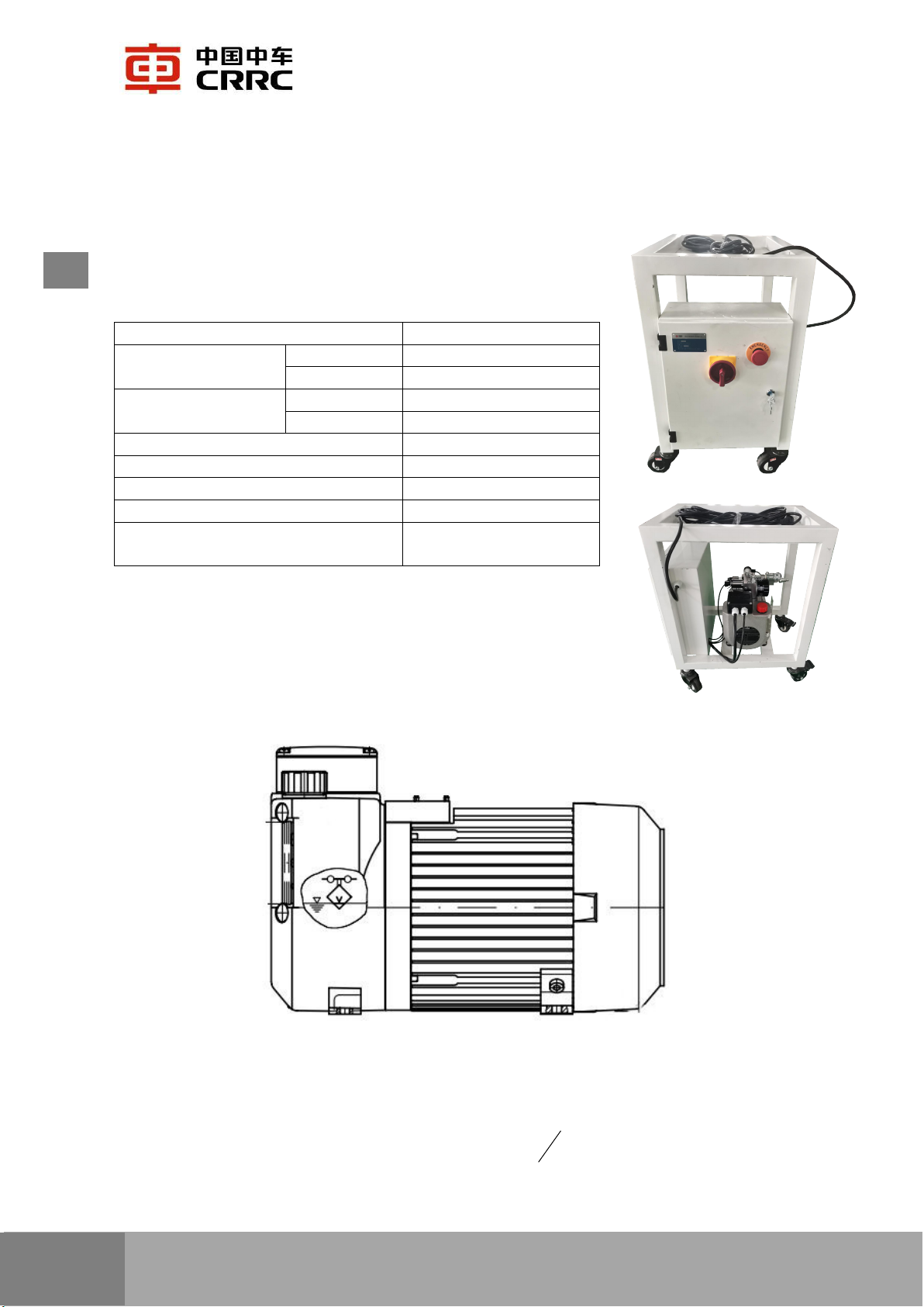
1. Structure
1.1 Technical Data
Motor
1.5kw
Flow
piston
pump
1.11L/min
gear
pump
4.0L/min
Max. Pressure
piston
pump
700bar
gear
pump
170bar
Gross
Weight
28kg
Unloading
Valve
10-150bar
Regulating
Valve
10-700bar
Pressure
Limiting
Valve
of
B
Way
10-340bar
Dimension 540mm×400mm×700m
m
1.2 Structure of Pump & Valve
Fig.1 Structure of Pump
The pump contains motor, pump head, tank, liquid level switch, cooling system, etc..
The viscosity of hydraulic fluid shall be 4~1500
s
mm 2in which the best practise is
Ⅱ

10~500
s
mm 2. The temperature shall be -25℃—+80℃. Depress the rivet tool in air for
several circles before use to make sure the hydraulic fluid fully fills the hydraulic system.
Fig. 2 Structure of Valves
The valves contains master limiting valve, unloading valve, pressure limiting valve of
B way, unloading changeover valve, magnetic directional valve, filter system, manifold
block.
1.3 Hydraulic Tube
The hydraulic tube is equipped with high-pressure tube sourcing from CEJN, and
quick disconnect couplers from Paker(paker371、paker372).
Recommended Hydraulic Fluid: 32# Anti-wear Hydraulic Fluid (temperature at
-12℃~20℃) & 46# Anti-wear Hydraulic Fluid (temperature at 20℃~50℃).
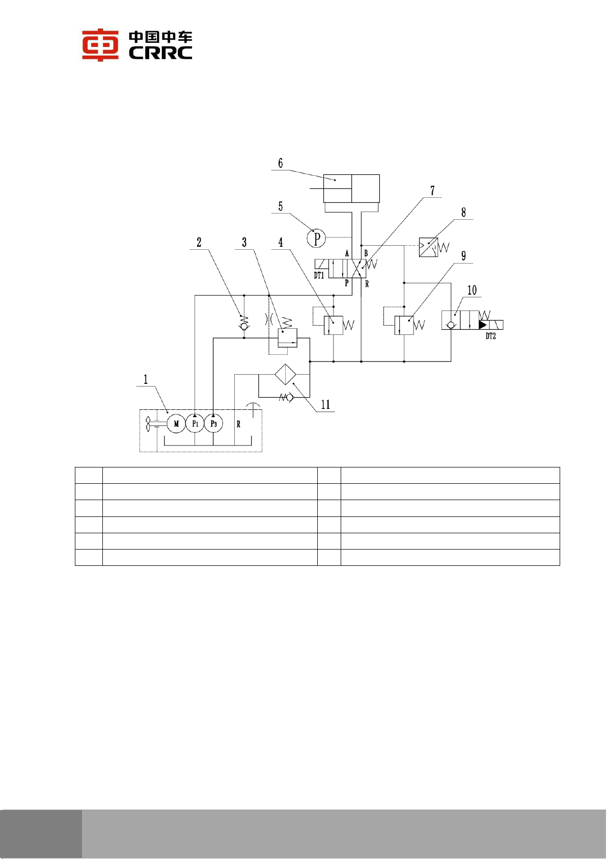
2. Principle of Operation
1 Hydraulic pump aggregate 7 Solenoid valve
2 Directional valve 8 Pressure relay
3 Unloading valve 9 Pressure-limiting valve
4 Overflow valve 10 Two-way solenoid valve
5 Pressure transmitter 11 Strainer
6 Installation tool
Fig. 3 Principle Diagram
When the tool trigger is depressed, motor runs, DT1 is powered on, and the left
contact of four-way solenoid closed, then the hydraulic unit start PULL circle. When
PULL pressure reaches to a pre-set value, the DT1 is shut down, and the right contact of
four-way solenoid closed, then the hydraulic unit start RETURN circle. When PUSH
pressure reaches a pre-set value, the motor shut down, and DT2 is powered on for 1s, the
pressure is released. See below for the action of solenoid valve.

3. Pressure Setting of PULL & RETURN
3.1 Recommended PULL and RETURN pressure:
Tool Model Nosepiece PULL Pressure RETURN Pressure
MS-2624PT MS-5106 4900-5800psi 2650psi-3200psi
MS-BT20 MS-7880L (Installation) 4050psi-4350psi 2650psi-3200psi
MS-7880CC (Cutting) 4650psi-5100psi 2650psi-3200psi
Status
Item
Trigger
Electrom
agnet
DT1
Electro
magnet
DT2
Motor
Status
Pressure
Relay
Start Pull + + - On Off
Pull Finished + + - On Off
Start Return - - - On On
Return Finished - - - On On
Unloading - - + Off Off
2

3.2 Adjusting the Pressure Setting
Fig. 4 Adjusting the Pressure
3.2.1 Master Regulating Valve for regulating the PULL pressure of installation and
cutting tool:
a. Turn the valve clockwise to rise the pull pressure;
b. Turn the valve counterclockwise to decrease the pull pressure.
3.2.2 Return Regulating Valve for regulating the RETURN pressure:
a. Loosen the locknut (white nut) on the valve;
b. Start pumping;
c. With a screwdriver, slowly turn the adjusting screw(black screw);
d. Turn the adjusting screw clockwise to rise the pressure, turn the adjusting screw
counterclockwise to decrease the pressure;
e. When the desired pressure is reached, lock the adjusting screw in position by
tightening the locknut while hold the position of the adjusting screw.
Master Regulating
Valve
Return Regulating
Valve

4. Preparation for Operation
a. Repairman and Operator must read manual prior to using equipment. A training
session with qualified personnel is recommended before using this equipment.
b. Check all hoses and tools for damage and leaks. The leaks of hydraulic fluid
leads to severe personal injury.
c. Keep the coupler of pipe away from dirt. Any dirt or fiber leads to defect and
must be cleaned up prior to using this equipment.
d. The thread sealant tape is recommended to seal the thread of pipe to avoid
leakage. DO NOT use plastic tape to enwind the thread of pipe, the chippings of plastic
tape leads to damage to valve.
e. Before connecting the tool trigger to hydraulic unit, the hydraulic pipe must be
connected to the hydraulic unit first.
5. Maintenance & Cautions
a. Keep the hydraulic unit clean.
b. Replace the hydraulic fluid once running for every 250 hours.
c. Disconnect the power supply of hydraulic unit while it is not supposed to be
used.
d. Inspect the level of hydraulic fluid regularly, add fluid as needed.
e. Do not move the hydraulic unit by hauling the pipes; protect the structure shell
from damage; protect the hydraulic unit from falling when moving it.
f. Inspect all pipes and hoses for signs of damage and leaks, replace the hoses and
accessories as needed.
g. Inspect all connection of tools everyday before work.
h. Regularly inspect the screws of tool and hydraulic unit for loosening.
i. Take care of all connections from break, scrap and joint failure when using this
hydraulic unit.

眉山中车紧固件科技有限公司
地址:中国·四川眉山市东坡区科工园二路
电话:182 2815 1235 0086 28 38283773
传真:0086 28 38164262
MEISHAN CRRC FASTENING SYSTEM CO.,LTD.
Add:Road No.2,Hi-tech Zone,Dongpo district,Meishan,Sichuan,
province,China
Tel:182 2815 1235 0086 28 38283773
Fax:0086 28 38164262
眉山中车紧固件科技有限公司
地址:中国·四川眉山市东坡区科工园二路
电话:182 2815 1235 0086 28 38283773
传真:0086 28 38164262
MEISHAN CRRC FASTENING SYSTEM CO.,LTD.
Add:Road No.2,Hi-tech Zone,Dongpo district,Meishan,Sichuan,
province,China
Tel:182 2815 1235 0086 28 38283773
Fax:0086 28 38164262
Table of contents


