manuals.online logo
Brands
  1. Home
  2. •
  3. Brands
  4. •
  5. CRU
  6. •
  7. Storage
  8. •
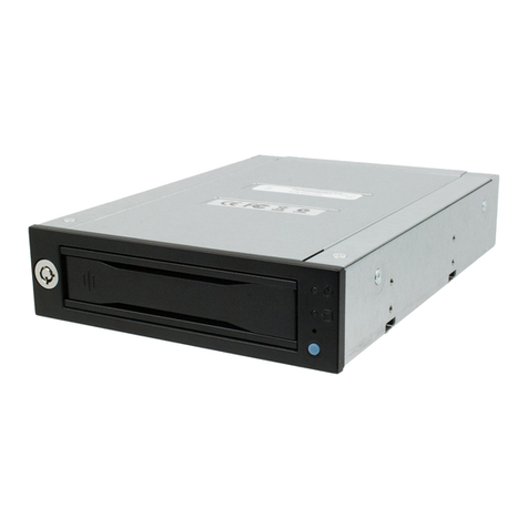
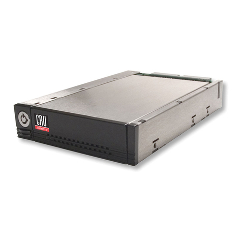
  9. CRU DataPort I User manual

CRU DataPort I User manual

DataPort™
Installation
Manual
COPYRIGHT
STATEMENT
CONNECTOR
RESOURCES
UNLIMITED,
Inc.
(CRU)
has
taken
care
to
ensure
the
accuracy
of
this
document.
However,
CRU
assumes
no
liability
for
errors
or
omissions
and
reserves
the
right
to
make
changes
without
further
notice
to
any
products
herein
to
improve
reliability,
function,
or
design.
CRU
provides
this
guide
without
warranty
of
any
kind,
either
implied
or
expressed,
including,
but
not
limited
to,
the
implied
warranties
of
merchantability
and
fitness
for
particular
purposes.
CRU
may
make
improvements
or
changes
in
the
product(s)
described
in
this
manual
at
any
time.
This
document
contains
proprietary
information
which
is
protected
by
copyright.
All
rights
are
reserved.
No
part
of
this
manual
may
be
photocopied,
reproduced,
or
translated
to
another
language
without
written
permission
from
CRU.
CRU
reserves
the
right
to
revise
this
publication
and
to
make
changes
in
content
from
time
to
time
without
obligation
on
the
part
of
CRU
to
provide
notification
of
such
revision
or
change.
TRADEMARKS
DataPort
is
a
trademark
of
CONNECTOR
RESOURCES
UNLIMITED,
Inc.
CRU
3.5"
Portable
Enclosure,
CRU
Half-Height
Enclosure,
CRU
1-Bay
Enclosure,
CRU
2-Bay
Enclosure,
CRU
4-
Bay
Enclosure
and
CRU
7-Bay
Enclosure
are
trademarks
of
Connector
Resources
Unlimited,
Inc.
Other
brand
or
product
names
are
trademarks
or
registered
trademarks
of
their
respective
holders.
Copyright©
1992-1996
by
Connector
Resources
Unlimited,
Inc.
All
rights
reserved.
INTRODUCTION
TO
THE
CRU
DATAPORT
Congratulations
on
your
purchase
of
the
CRU
DataPort
Removable
Storage
Module.
The
DataPort
allows
you
to
easily
remove
a
3.5"
hard
drive
from
your
PC,
workstation,
disk
array,
sub-system
or
minicomputer.
The
DataPort
cartridge
provides
a
simple
and
inexpensive
way
to
transport
data
between
computers
and
is
also
useful
for
on-line
back-up
and
storage
of
critical
files.
Sensitive
information
can
be
easily
removed
and
secured.
The
DataPort
is
designed
for
use
in
hot-swap
and
hot-removable
environments,
thus
making
it
ideal
for
RAID
applications.
The
DataPort
consists
of
a
frame,
cartridge
and/or
top
and
bottom
covers.
The
frame
can
be
fitted
into
any
standard
5.25"
half-height
drive
bay.
The
DataPort
offers
keylock
or
latch
versions,
as
well
as
SCSI
or
IDE
interface
models.
CRU
DataPort
is
a
U.S.
patented
product.
Make
sure
to
check
the
patent
label
for
authenticity.
CRU
offers
a
metal
version
of
the
cartridge
for
those
who
need
FCC
approval.
Features
and
Options
DataPort
I
DataPort
IV
DataPort
V
DataPort
VII
args
Maral
TUNER
Aluminum
Alloy
Aluminum
Alloy
|
Aluminum
Alloy
SCSI
ID
Selector
Switch
N/A
|
Dil
|
Dia
Dial
with
Display
ooling
Fan
Yes
SCSI
Fast
/
Wide
option
_
|
N/A
Yes Yes
HDD
Activity
LED
Optional
Yes
Yes Yes
SCSI
and
IDE
SCSI
and
IDE
SCSI
and
IDE
SCSI
Preparation
for
Installation
Note:
To
prevent
data
loss,
read
this
manual
thoroughly
before
installing
or
operating
the
DataPort.
Before
touching
any
electrical
equipment,
ground
yourself
by
touching
the
metal
part
of
your
computer
chassis.
This
discharges
static
electricity
and
prevents
any
damage
to
your
computer.
CRU
is
not
responsible
for
static
discharge
damages.
Tools
Required:
e
Phillips
screwdriver.
e
Small
flat
screwdriver.
Other
items
that
may
be
needed
are:
e
Hard
drive
manual
to
set
the
SCSI
ID
for
a
SCSI
drive
or
to
set
the
master
or
slave
mode
for
an
IDE
drive.
e
SCSI
bus
terminator.
For
external
application,
a
50-pin
SCSI
passive
or
active
terminator
should
be
used
to
ter-
minate
the
end
of
the
SCSI
chain.
For
internal
application,
an
internal
SCSI
bus
terminator,
usually
a
220
Ohm
resistor
pack,
is
installed
on
the
SCSI
drive.
CRU
DataPort™
Installation
Manual
TABLE
OF
CONTENTS
CRU
JWataPort
I
ssssscssseisssessecesectscccscsosvcancscsnnssccpssmsccscaeianagaasaseassneevenidacvesecencscannan
fined
ic
HR
HNN
HF
€
5
Frame
Installation
e
—————————————
MÀ
5
Cartridge
Installation
——"——9——9——————————!
M——————
7
CRU
DataPort
IV
...........
—
TET
Lib
os
siek
ka
a
klè
Hn
e
pa
a
kk
a
ies)
^
PACKAGE!
Contents
server
Dm
9
Eranme:Installation...-..
cscs
sacs
eios
gites
cec
FU
cess;
eccL
PPS
ERE
it
ET
EDD
STEN
SEY
pe
EE
UE
Se
RENS
DN
9
Cartridge
Installation
perm
——————
11
CRU
DataPort
V
..........
DN
UR
GEM
GG
PE
DD
DIN
LO
uc"
—————
13
iii
A
taal
o't
iu
rr
a
AE
AF
Y
FL
HE
S
13
Cartridge
Installation
em
15
CRU
ata
OPEV
EL
oeste
kim
eklè
AGOA
O
YEAR
AGO
T
PACKAGES
COATON
rl
m
17
Ig
cura
ielirtir)
e
——————À
17
Cartridge
Installation
e
————————————
19
TABLE
OF
CONTENTS
=
1
CRU
DataPort™
Installation
Manual
Connecting
The
SCSI
ID
Selector
Switch
..................
———À
21
Cartridge
SCUUP
risk
kis
—————
21
Frame
SOT
e
25
Operation
..................
rere
/———————
AAAN
————
MN
29
Turn
on
the
DOWer
NU
——_———
YO
Y
YH
29
ern
Ee
m
29
REMOVE
the
Cn
I
———————————————
29
Trouble
SHOOCNQ.
———————————————
30
Technical
SAP
PÒL
RETI
LC
EL
M
30
2
m
TABLE
OF
CONTENTS
CRU
P/N
A4-003-0001,
Rev
B
CRU
DataPort™
Installation
Manual
LIST
OF
FIGURES
Figure
1
CRU
DafaPort
sissccccsscscasassscssasssscazasessacessssaiaccssssensnonecenveserecesveieeseceneseounnses
4
Puurs
2-
“CRU
DAAPOTE
IV.
a
eere
———
O
WU
8
Figure
3
CRU'DataP
orf
V
sèvsreeiegonianasonskonensonassssninaosasasirassdessnossisassssovosonoosostynsenon
12
Figure
4
CRU
DataPort
VIL
sssssssssscscsscasisscscsrcssscscassscccocssersorosessossereansonesensanssnsosenee
16
Figure
3.8
SCSTTD
Beader
layout:
ooo
dae
don
kree
soon
ka
eee
ap
kès
one
ong
oka
ets
RA
YE
21
Figure
6
CRU
DataPort
I
SCSI
cartridge
cable
connection.
...............................
22
Figure
7
CRU
DataPort
IV,
V
and
VII
SCSI
cartridge
cable
connection..........
23
Figure
8
CRU
DataPort
V
SCSI
Fast/Wide
cartridge
cable
connection.
...........
24
Figure
9
Back
view
of
CRU
DataPort
I
frame.
...veeereooeoooooosoooeononsooooonovonoooosonosonose
25
Figure
10
Back
view
of
CRU
DataPort
IV
SCSI
frame.
........................................
26
Figure
11
Back
view
of
CRU
DataPort
V
SCSI
frame.......................9........
coco...
26
Figure
12
Back
view
of
CRU
DataPort
V
SCSI
Fast/Wide
frame.
.......................
27
Figure
13
Back
view
of
CRU
DataPort
VII
SCSI
frame........................................
28
LIST
OF
FIGURES
w
3
CRU
DataPort
Installation
Manual
-
LA
SS
Lu
|
ao
Se
ee
PÈ
"
ec
a
e
Frame
assembly
p
sd
s
L
sen
Keylock
or
Latch
—
m
É
Power
LED
Data
cable
Figure
1
CRU
DataPort
l.
4
a
CRU
DATAPORT
I
CRU
P/N
A4-003-0001,
Rev
B
CRU
DataPort
Installation
Manual
CRU
DATAPORT
I
PACKAGE
CONTENTS:
The
CRU
DataPort
I
kit
includes
all
the
necessary
hardware
to
install
a
3.5"
hard
drive
in
a
5.25"
drive
bay.
Before
installing
the
CRU
DataPort
I,
verify
that
the
following
items
have
been
included
in
the
package.
Quantity
Description
DataPort
I
frame
assembly
DataPort
I
cartridge
assembly
Metal
screen
6-32
x
3/8"
Phillips
pan
head
screws
for
hard
drive
mounting
6-32
x
1/4"
flat
head
screws
for
AT
rails
or
frame
mounting
2-56
slatted
pan
head
self
tapping
screws
for
screen
mounting
Plastic
AT
rails
Key
for
keylock
version
If
any
of
the
above
items
are
missing
or
you
need
special
parts,
contact
your
dealer
or
CRU
for
instructions
regarding
replacement
or
service.
NN
AAR
—
You
can
order
additional
cartridges
for
multiple
drives.
FRAME
INSTALLATION
1.
Turn
off
the
computer
and
disconnect
the
power
cord
from
the
electrical
outlet.
Before
working
on
your
computer,
wait
one
minute
for
any
residual
energy
to
dissipate.
CRU
DATAPORT
|
=u
5
CRU
DataPort
Installation
Manual
2.
Remove
the
cover
of
the
computer.
Review
your
computer
user
manual
for
how
to
remove
the
cover,
then
set
it
aside.
3.
Locate
a
5.25"
drive
bay
with
external
access.
Identify
the
5.25"
half-height
bay
in
which
you
plan
to
mount
the
DataPort
I.
Study
the
bay
to
determine
the
loca-
tion
of
mounting
holes
or
whether
mounting
rails
are
necessary.
Remove
any
filler
plates
that
may
be
present.
4.
Install
mounting
rails.
If
the
drive
bay
requires
mounting
rails,
install
one
on
each
side
of
the
frame.
The
mounting
rails
should
be
pro-
vided
with
your
computer
system.
The
CRU
DataPort
I
includes
two
standard
AT
Rails.
5.
Mounting
the
frame
assembly.
Insert
the
frame
assembly
into
the
5.25"
bay.
Secure
the
frame
assembly
with
the
6-32
screws
provided
or
with
the
proper
hardware.
6.
Connect
the
DC
power
cable
and
the
data
cable.
Locate
an
available
4-pin
DC
power
cable
from
the
computer
power
supply,
plug
it
to
the
receptacle
on
the
frame.
Locate
the
data
cable
from
the
controller,
connect
it
to
the
I/O
connector
on
the
frame.
Ensure
that
pin1
of
the
I/O
connector
(printed
on
the
circuit
board)
matches
pin1
on
the
cable
(identified
by
the
red
dots).
7.
If
you
are
installing
a
SCSI
model,
and
are
using
an
external
SCSI
ID
selector
switch,
refer
to
“CRU
DataPort
I
SCSI
frame"
on
page
25.
Otherwise,
go
to
*Cartridge
Installation"
below.
6
»
CRU
DATAPORT
I
CRU
P/N
A4-003-0001,
Rev
B
CRU
DataPort
Installation
Manual
CARTRIDGE
INSTALLATION
1.
Connect
the
DC
power
cable
and
data
cable
to
the
drive.
Plug
the
4-pin
DC
power
cable
into
the
power
connector
on
the
drive
and
ensure
it
is
fully
seated.
Connect
the
data
cable
that
matches
your
particular
drive
(40-pin
for
an
IDE
drive
or
50-pin
for
a
SCSI
drive).
Ensure
the
pin!
on
the
data
cable
match
the
pin
1
on
the
drive
I/O
connector
header.
If
you
are
installing
a
SCSI
drive
with
and
optional
BCD
cable
for
a
SCSI
ID,
Refer
to
“CRU
DataPort
I
cartridge”
on
page
22.
Otherwise
go
to
step
3.
Install
the
drive
in
the
cartridge.
Place
the
drive
in
the
cartridge,
use
the
four
6-32
x
3/8"
pan-head
screws
provided
to
mount
the
drive.
Position
the
cables
inside
the
cartridge
assembly
so
that
they
are
completely
enclosed
within
the
cartridge.
Install
the
screen
kit.
Position
the
screen
on
the
cartridge,
aligning
the
six
slotted
tabs
along
the
edge
of
the
screen
with
the
appropriate
holes
in
the
cartridge.
Secure
each
tab
with
one
2-56
self-tapping
screw.
Insert
the
cartridge
into
the
frame
assembly.
Ensure
that
the
keylock
or
latch
of
the
DataPort
I
is
in
the
“open”
(vertical)
position.
Position
the
cartridge
on
the
guide
rails,
and
slide
the
cartridge
into
the
frame.
Using
thumb
pressure,
fully
seat
the
cartridge
in
the
frame,
and
then
“lock”
the
unit
with
the
keylock
or
the
latch.
Replace
the
cover.
Carefully
recheck
the
installation
procedure
above
to
ensure
that
everything
is
in
order.
Replace
the
cover
on
the
computer
by
reversing
the
seguence
of
steps
that
you
used
to
remove
it.
CRU
DATAPORT
|
»
7
CRU
DataPort
Installation
Manual
IN
pp
Keylock
or
Latch
Power
LED
HDD
activity
LED
HDD
activity
LED
cable
SCSI
ID
selector
switch
cable
(SCSI)
model
3.5"
drive
Figure
2
CRU
DataPort
IV.
8
=»
CRU
DATAPORT
IV
CRU
P/N
A4-003-0001,
Rev
B
CRU
DataPort
Installation
Manual
CRU
DATAPORT
IV
PACKAGE
CONTENTS:
The
CRU
DataPort
IV
kit
includes
all
the
necessary
hardware
to
install
a
3.5"
hard
drive
in
a
5.25"
drive
bay.
Before
installing
the
CRU
DataPort
IV,
verify
that
the
following
items
have
been
included
in
the
package.
Quantity
Description
DataPort
IV
frame
assembly
DataPort
IV
cartridge
assembly
Metal
covers
6-32
x
3/8"
flat
head
screws
for
hard
drive
mounting
M3
x
3/8"phillips
pan-head
screws
frame
mounting
SCSI
ID
selector
switch
cable
HDD
activity
LED
cable
Key
for
keylock
version
If
any
of
the
above
items
are
missing
or
you
need
special
parts,
contact
your
dealer
or
CRU
for
instructions
regarding
replacement
or
service.
Nee
A
AN
oi
gn
You
can
order
additional
cartridges
for
multiple
drives.
FRAME
INSTALLATION
1.
Turn
off
the
computer
and
disconnect
the
power
cord
from
the
electrical
outlet.
Before
working
on
your
computer,
wait
one
minute
for
any
residual
energy
to
dissipate.
CRU
DATAPORT
IV
=
9
CRU
DataPort
Installation
Manual
2.
Remove
the
cover
of
the
computer.
Review
your
computer
user
manual
for
how
to
remove
the
cover,
then
set
it
aside.
3.
Locate
a
5.25"
drive
bay
with
external
access.
Identify
the
5.25"
half-height
bay
in
which
you
plan
to
mount
the
DataPort
IV.
Study
the
bay
to
determine
the
location
of
mounting
holes
or
whether
mounting
rails
are
necessary.
Remove
any
filler
plates
that
may
be
present.
4.
Install
mounting
rails.
If
the
drive
bay
requires
mounting
rails,
install
one
on
each
side
of
the
frame.
The
mounting
rails
should
be
pro-
vided
with
your
computer
system.
5.
Mounting
the
frame
assembly.
Insert
the
frame
assembly
into
the
5.25"
bay.
Secure
the
frame
assembly
with
the
M3
screws
provided
or
with
the
proper
hardware.
6.
Connect
the
DC
power
cable
and
the
data
cable.
Locate
an
available
4-pin
DC
power
cable
from
the
computer
power
supply,
plug
it
to
the
receptacle
on
the
frame.
Locate
the
data
cable
from
the
controller,
connect
it
to
the
I/O
connector
on
the
frame.
Ensure
that
pin]
of
the
I/O
connector
matches
pinl
on
the
cable
(identified
by
the
red
dots).
7.
If
you
are
installing
a
SCSI
model,
and
are
using
an
external
SCSI
ID
selector
switch,
refer
to
“CRU
DataPort
IV
and
V
SCSI
frame"
on
page
25.
Otherwise,
go
to
*Cartridge
Installation?
below.
10
a
CRU
DATAPORT
IV
CRU
P/N
A4-003-0001,
Rev
B
CRU
DataPort
Installation
Manual
CARTRIDGE
INSTALLATION
1.
Remove
the
cartridge
top
and
bottom
covers.
2.
Connect
the
DC
power
cable
and
data
cable
to
the
drive.
Plug
the
4-pin
DC
power
cable
into
the
power
connector
on
the
drive
and
ensure
it
is
fully
seated.
Connect
the
data
cable
that
matches
your
particular
drive
(40-pin
for
an
IDE
drive
or
50-pin
for
a
SCSI
drive).
Ensure
the
pinl
on
the
data
cable
match
the
pin
1
on
the
drive
I/O
connector
header.
3.
Ifyou
are
installing
a
SCSI
model,
Refer
to
“CRU
DataPort
IV,
V,
and
VII
SCSI
Cartridge"
on
page
22.
Otherwise
go
to
step
3.
4.
Install
the
drive
in
the
cartridge.
Place
the
drive
in
the
cartridge,
use
the
four
6-32
x
3/8"
flat
head
screws
provided
to
mount
the
drive.
Position
the
cables
inside
the
cartridge
assembly
so
that
they
are
completely
enclosed
within
the
cartridge.
5.
Replace
the
cartridge
top
and
bottom
covers
6.
Insert
the
cartridge
into
the
frame
assembly.
Ensure
that
the
keylock
or
latch
of
the
DataPort
IV
is
in
the
“open”
(vertical)
position.
Position
the
cartridge
on
the
guide
rails,
and
slide
the
cartridge
into
the
frame.
Using
thumb
pressure,
fully
seat
the
cartridge
in
the
frame,
and
then
“lock”
the
unit
with
the
keylock
or
the
latch.
7.
Replace
the
computer
cover.
Carefully
recheck
the
installation
procedure
above
to
ensure
that
everything
is
in
order.
Replace
the
cover
on
the
computer
by
reversing
the
sequence
of
steps
that
you
used
to
remove
it.
CRU
DATAPORT
IV
=
11
CRU
DataPort
Installation
Manual
HDD
activity
LED
cable
SCSI
ID
selector
switch
l
cable
(SCSI
model)
3.5"
drive
Power
LED
HDD
activity
LED
Figure
3
CRU
DataPort
V.
12
»
CRU
DATAPORT
V
CRU
P/N
A4-003-0001,
Rev
B
CRU
DataPort
Installation
Manual
CRU
DATAPORT
V
PACKAGE
CONTENTS:
The
CRU
DataPort
V
kit
includes
all
the
necessary
hardware
to
install
a
3.5"
hard
drive
in
a
5.25"
drive
bay.
Before
installing
the
CRU
DataPort
V,
verify
that
the
following
items
have been
included
in
the
package.
Quantity
Description
DataPort
V
frame
assembly
DataPort
V
cartridge
assembly
Metal
covers
6-32
x
3/8"
flat
head
screws
for
hard
drive
mounting
M3
x
3/8"phillips
pan-head
screws
frame
mounting
SCSI
ID
selector
switch
cable
HDD
activity
LED
cable
Key
for
keylock
version
Nee
ds
AN
mm
If
any
of
the
above
items
are
missing
or
you
need
special
parts,
contact
your
dealer
or
CRU
for
instructions
regarding
replacement
or
service.
You
can
order
additional
cartridges
for
multiple
drives.
FRAME
INSTALLATION
1.
Turn
off
the
computer
and
disconnect
the
power
cord
from
the
electrical
outlet.
Before
working
on
your
computer,
wait
one
minute
for
any
residual
energy
to
dissipate.
CRU
DATAPORT
V
u
13
CRU
DataPort
Installation
Manual
2.
Remove
the
cover
of
the
computer.
Review
your
computer
user
manual
for
how
to
remove
the
cover,
then
set
it
aside.
3.
Locate
a
5.25"
drive
bay
with
external
access.
Identify
the
5.25"
half-height
bay
in
which
you
plan
to
mount
the
DataPort
V.
Study
the
bay
to
determine
the
location
of
mounting
holes
or
whether
mounting
rails
are
necessary.
Remove
any
filler
plates
that
may
be
present.
4.
Install
mounting
rails.
If
the
drive
bay
requires
mounting
rails,
install
one
on
each
side
of
the
frame.
The
mounting
rails
should
be
pro-
vided
with
your
computer
system.
5.
Mounting
the
frame
assembly.
Insert
the
frame
assembly
into
the
5.25"
bay.
Secure
the
frame
assembly
with
the
M3
screws
provided
or
with
the
proper
hardware.
6.
Connect
the
DC
power
cable
and
the
data
cable.
Locate
an
available
4-pin
DC
power
cable
from
the
computer
power
supply,
plug
it
to
the
receptacle
on
the
frame.
Locate
the
data
cable
from
the
controller,
connect
it
to
the
I/O
connector
on
the
frame.
Ensure
that
pinl
of
the
1/0
connector
matches
pin!
on
the
cable
(identified
by
the
red
dots).
7.
If
you
are
installing
a
SCSI
model,
and
are
using
an
external
SCSI
ID
selector
switch,
refer
to
“CRU
DataPort
IV
and
V
SCSI
frame"
on
page
25
or
“CRU
DataPort
V
SCSI
Fast/Wide
frame"
on
page
27.
Otherwise,
go
to
*Cartridge
Installation"
below.
14
=
CRU
DATAPORT
V
CRU
P/N
A4-003-0001,
Rev
B
CRU
DataPort
Installation
Manual
CARTRIDGE
INSTALLATION
1.
Remove
the
cartridge
top
and
bottom
covers.
2.
Connect
the
DC
power
cable
and
data
cable
to
the
drive.
Plug
the
4-pin
DC
power
cable
into
the
power
connector
on
the
drive
and
ensure
it
is
fully
seated.
Connect
the
data
cable
that
matches
your
particular
drive
(40-pin
for
an
IDE
drive
or
50-pin
for
a
SCSI
drive).
Ensure
the
pinl
on
the
data
cable
match
the
pin
1
on
the
drive
I/O
connector
header.
3.
If
you
are
installing
a
SCSI
model,
refer
to
“CRU
DataPort
IV,
V,
and
VII
SCSI
Cartridge"
on
page
22
or
*CRU
DataPort
V
and
VII
SCSI
Fast/Wide
Cartridge"
on
page
23.
Otherwise
go
to
step
3.
4.
Install
the
drive
in
the
cartridge.
Place
the
drive
in
the
cartridge,
use
the
four
6-32
x
3/8"
flat
head
screws
provided
to
mount
the
drive.
Position
the
cables
inside
the
cartridge
assembly
so
that
they
are
completely
enclosed
within
the
cartridge.
Replace
the
cartridge
top
and
bottom
covers
Insert
the
cartridge
into
the
frame
assembly.
Ensure
that
the
keylock
or
latch
of
the
DataPort
V
is
in
the
“open”
(vertical)
position.
Position
the
cartridge
on
the
guide
rails,
and
slide
the
cartridge
into
the
frame.
Using
thumb
pressure,
fully
seat
the
cartridge
in
the
frame,
and
then
“lock”
the
unit
with
the
keylock
or
the
latch.
7.
Replace
the
computer
cover.
Carefully
recheck
the
installation
procedure
above
to
ensure
that
everything
is
in
order.
Replace
the
cover
on
the
computer
by
reversing
the
sequence
of
steps
that
you
used
to
remove
it.
CRU
DATAPORT
V
=
15

This manual suits for next models

3

Other CRU Storage manuals

CRU DataPort 10 Secure Series User manual

CRU

CRU DataPort 10 Secure Series User manual

CRU Forensic Labdock S5 User manual

CRU

CRU Forensic Labdock S5 User manual

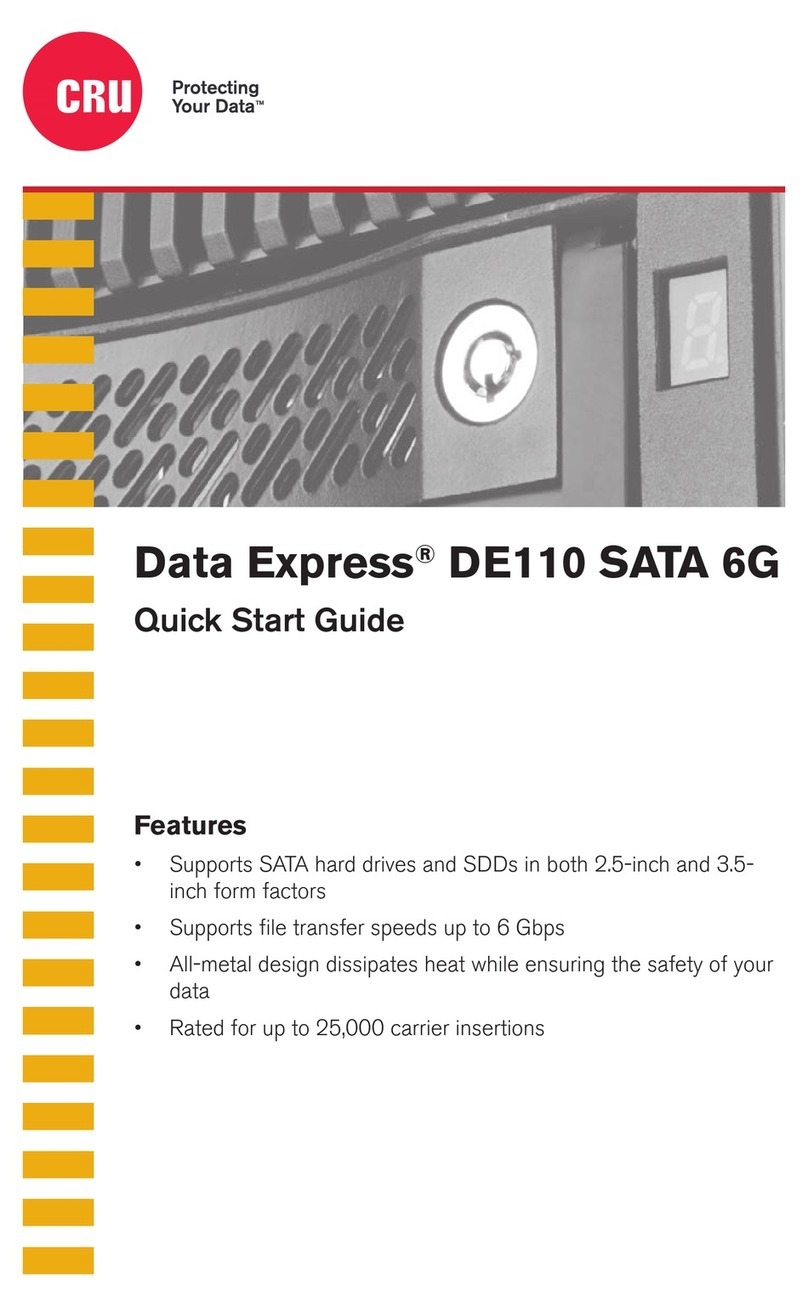
CRU Data Express DE110 SATA 6G User manual

CRU

CRU Data Express DE110 SATA 6G User manual

CRU RAX210-3QR User manual

CRU

CRU RAX210-3QR User manual

CRU RTX 3QJ Series User manual

CRU

CRU RTX 3QJ Series User manual

CRU Dataport 25 SL User manual

CRU

CRU Dataport 25 SL User manual

CRU RTX Secure 410-3QR User manual

CRU

CRU RTX Secure 410-3QR User manual

CRU ToughTech Secure m3 User manual

CRU

CRU ToughTech Secure m3 User manual

CRU QX118 User manual

CRU

CRU QX118 User manual
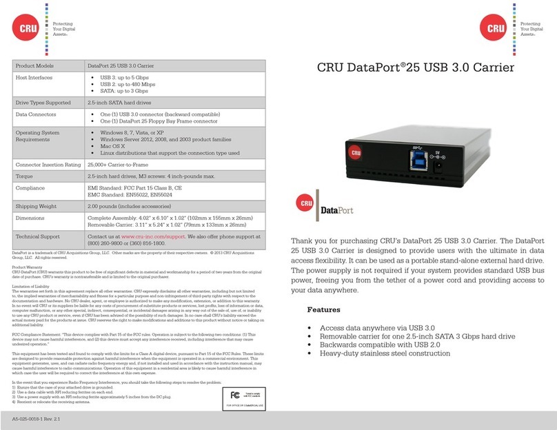
CRU DataPort DP20 User manual

CRU

CRU DataPort DP20 User manual

CRU DataPort 3 User manual

CRU

CRU DataPort 3 User manual

CRU Data Express DX115 DC User manual

CRU

CRU Data Express DX115 DC User manual

CRU RAX RAX210-SJ User manual

CRU

CRU RAX RAX210-SJ User manual

CRU ioSafe Solo Hawk User manual

CRU

CRU ioSafe Solo Hawk User manual

CRU DataPort 25 IDE-to-SATA User manual

CRU

CRU DataPort 25 IDE-to-SATA User manual

CRU DataPort 25 User manual

CRU

CRU DataPort 25 User manual
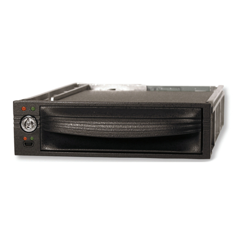
CRU Data Express DX175 User manual

CRU

CRU Data Express DX175 User manual

CRU DataPort HotDock External Drive Bay User manual
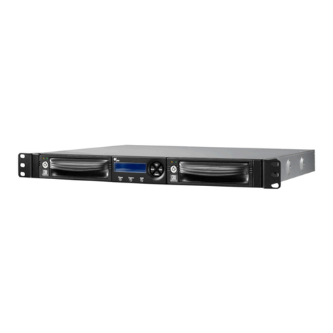
CRU

CRU DataPort HotDock External Drive Bay User manual

CRU RTX220-3QR User manual

CRU

CRU RTX220-3QR User manual

CRU Mouse Jiggler MJ-2 User manual

CRU

CRU Mouse Jiggler MJ-2 User manual

Popular Storage manuals by other brands

FOCO Office-Container Assembly instructions

FOCO

FOCO Office-Container Assembly instructions

Quantum LTO-3 installation guide

Quantum

Quantum LTO-3 installation guide

Western Digital WDMT3200 - My Passport Studio user manual

Western Digital

Western Digital WDMT3200 - My Passport Studio user manual

Synology FlashStation FS3600 Hardware installation guide

Synology

Synology FlashStation FS3600 Hardware installation guide

Quantum DLTtape DLT 8000 product manual

Quantum

Quantum DLTtape DLT 8000 product manual

Seagate Technology ST2000VT000 product manual

Seagate Technology

Seagate Technology ST2000VT000 product manual

JVC LYT1085-001A Installation and connection guide

JVC

JVC LYT1085-001A Installation and connection guide

Buffalo HD-PV320U2 Specifications

Buffalo

Buffalo HD-PV320U2 Specifications

IBM Cloud Object Storage System Slicestor 2212... Appliance Manual

IBM

IBM Cloud Object Storage System Slicestor 2212... Appliance Manual

Seagate Momentus 5400 product manual

Seagate

Seagate Momentus 5400 product manual

Hama Vilitas FlashPen USB 3.0 Operating	 instruction

Hama

Hama Vilitas FlashPen USB 3.0 Operating instruction

Sans Digital Towerraid 6G series Detailed manual

Sans Digital

Sans Digital Towerraid 6G series Detailed manual

Synology DiskStation DS124 product manual

Synology

Synology DiskStation DS124 product manual

Quantum DLTtape DLT 2000 supplementary guide

Quantum

Quantum DLTtape DLT 2000 supplementary guide

SimpleTech SimpleDrive SP-U25/120 quick start guide

SimpleTech

SimpleTech SimpleDrive SP-U25/120 quick start guide

Transcend TS120GSJ25T Specifications

Transcend

Transcend TS120GSJ25T Specifications

Maxtor OneTouch 4 Plus Specifications

Maxtor

Maxtor OneTouch 4 Plus Specifications

Apricorn Aegis Padlock quick start guide

Apricorn

Apricorn Aegis Padlock quick start guide

manuals.online logo
manuals.online logoBrands
  • About & Mission
  • Contact us
  • Privacy Policy
  • Terms and Conditions

Copyright 2025 Manuals.Online. All Rights Reserved.