CRUSSIS e-Full 10.9 User manual

c´ƴŅÚĩŞŅƚdžĜƋĝ
åĬåĩƋųŅĩŅĬ±
ǏĞĥƒåƐžĞƐžƽŇƣƐjízdu!
c´ƴŅÚűŞŅƚdžĜƋĜååĬåĩƋųŅÆĜÏƼĩĬ±F)ĬåÏƋųĜÏÆĜÏƼÏĬåƚŸåųĵ±Ĺƚ±ĬF:åÆų±ƚÏĘŸ±ĹƵåĜŸƚĹčüƟų)ĬåĩƋųŅü±Ęųų±Ú
ǏЃåƐžĞƐžƽŇĥƣ jazdu!
)ĻĥŇDžƐDžŇƣŹƐride!
:åĻĞåĔåĻƐĞåƐFĚŹåƐFahrt!
CZ / SK / EN / DE
GX Ultimate
e-Full 10.9
ONE-Full 10.9
e-Full 9.9
ONE-Full 9.9

105
EN
Contents
Preface..............................................................................................................................106-108
General Notices................................................................................................................109-115
Rear Shock Adjustment .................................................................
..........
.........
.............115-118
ElectricBikeSystem..........................................................................................................118-124
Electric Bike Control (Color LCD Display).......................................................................124-151
Troubleshooting......................................................................................................................152
Maintenance and Storage.......................................................................................................153
Warnings..................................................................................................................................154
Warranty...........................................................................................................................154-155

106
EN
Preface
Dear users,
Thank you for purchasing the CRUSSIS electric bike! We appreciate your choice of our
product. For the proper functioning of the CRUSSIS electric bike, please carefully read
the product information before using it. The following text provides a description of all
the details (including device installation, settings, and regular use of the display) related
to the use of the electric bike. This manual will also help you address any uncertainties
or issues.
CRUSSIS electrobikes s.r.o. wishes you many wonderful and safe kilometers on your
new electric bike.
You can find a list of CRUSSIS dealers on the website www.crussis.com.
What is an electric bike?
It is a conventional bicycle equipped with an electric motor. The motor can be located in the cen-
ter, rear, or front hub. The electric motor may have a power not exceeding 250 W. The maximum
assistance speed is limited to 25 km/h, and this limitation corresponds to the European standard
EN 15194-1 (the electric motor turns offwhen this speed is exceeded and turns on again once the
speed drops below this threshold). Additionally, the bike is equipped with a battery, which can be
placed in the frame or on the rear carrier. The most critical parameters of the battery are voltage
and capacity. Higher values lead to an increased electric bike range. Currently, the most common-
ly used batteries are lithium-ion (Li-ion) batteries. The advantage of these batteries lies mainly in
their low weight and long lifespan. Regular charging of the battery is important to extend its li-
fespan. Communication between individual electrical components is managed by a control unit,
which evaluates data from various sensors to regulate the electric motor's power output accor-
dingly. The operation of the electric motor is facilitated through a control panel, which provides
information about the battery status, assistance level, and remaining range. Most displays also in-
clude information about the time, speed, and distance covered. The motor's function is activated
by pedaling, detected by a specialized sensor positioned in the pedal area. On an electric bike, you
must continuously pedal, and the motor simply assists you. The pedaling sensor is responsible for
informing the control unit whether the rider has started or stopped pedaling, and it reports pe-
daling frequency. This function is managed by either a magnetic strip sensor or a torque sensor.
The magnetic strip sensor is a basic sensor that operates on a magnetic principle. Installed on the
bottom bracket, this sensor monitors pedaling frequency. Activation of the pedaling sensor while
pedaling backward is not possible due to magnet phasing. Torque sensors are used in more expen-
sive, sporty bikes. Unlike magnetic sensors, they provide information about both pedaling frequen-
cy and the force applied to the pedal. A torque sensor is ideal for off-road riding, where pedaling
frequency frequently changes. When greater force is needed while pedaling, the motor provides
more power instantly. Conversely, when riding downhill and applying less pressure to the pedal,
the motor's function is limited, conserving battery energy. You can initiate movement on the electric
bike using the control button located on the display controller, but only up to the maximum
allowed speed of 6 km/h (used for assistance while walking). An electric bike that meets the Europe
an standard EN 15194-1 is legally regarded as a regular bicycle on public roads. This means you can
ride on bike paths, do not require a driver's license, and helmets are mandatory only for individu-
als under the age of 18. We recommend the use of cycling helmets for all users regardless of age.

107
EN
Turning on the electric bike
1. Turn on the battery by briefly pressing the power on/offbutton on the frame (for more details,
see page 121).
2. Turn on the display by pressing and holding the power on/offbutton on the display for about 2
seconds.
3. On the display, select the desired level of assistance (for more about the display, see pages 124-
151).
Turning offthe electric bike
1. Turn offthe display by briefly pressing the power on/offbutton on the display.
2. Turn offthe battery by pressing and holding the power on/offbutton on the frame for about 2
seconds.
Electric Bike Components
e-Full 9.9 / ONE-Full 9.9
9. cranks
1. battery
2. motor
3. control Panel
4. torque Sensor
5. brake Levers 6. battery Lock
7. brakes
8. shifter lever
10. thru axle 11. derailleur
12. tire and rim
10. thru axle
13. rear shock
14. fork
15. seatpost
16. battery on/offbutton
9
10
11
12
13
14
15
16
battery
motor
control Panel (LCD Display)
torque Sensor Inside the Motor
brake Levers
battery Lock (on the other side)
brakes
shifter lever
cranks, pedals are not depicted
thru axle
derailleur
tire and rim
rear shock absorber
fork
seatpost
battery on/offbutton
1
2
3
4
5
6
7
8

108
EN
9
10
11
12
13
14
15
16
Electric Bike Components
e-Full 10.9 / ONE-Full 10.9
battery
motor
control Panel (LCD Display)
torque Sensor Inside the Motor
brake Levers
battery Lock (on the other side)
brakes
shifter lever
cranks, pedals are not depicted
thru axle
derailleur
tire and rim
rear shock absorber
fork
telescopic seatpost
battery on/offbutton
1
2
3
4
5
6
7
8
9. cranks
1. battery
2. motor
3. control Panel
4. torque Sensor
5. brake Levers 6. battery Lock
7. brakes
8. shifter lever
10. thru axle 11. derailleur
12. tire and rim 10. thru axle
13. rear shock
14. fork
15. telescopic seatpost
16. battery on/offbutton

109
EN
GENERAL NOTICE
Riding an electric bicycle, like any other sport, carries the risk of injury and damage. If you want to
use an electric bicycle, you must familiarize yourself with and adhere to the rules of safe electric
bicycle riding, proper use, and maintenance of the electric bicycle. Regular maintenance and proper
usage will reduce the risk of injury and prolong the product's lifespan.
The e-Full models of electric bicycles are suitable for riding on paved roads, cycling paths, gravel
and forest trails, and off-road riding. The electric bicycles are equipped with tires featuring a rugged
pattern to ensure sufficient traction for off-road riding. Therefore, when riding on smooth surfaces
(such as asphalt or concrete), vibrations may occur.
Intended Use: The electric bike is intended for recreational purposes for consumer use.
Electric bikes are not suitable for wading, jumping, or high-impact landings.
Do not use them for extreme riding in rough terrain (downhill, enduro, obstacle riding)!
We recommend assembling and adjusting the electric bike at an authorized electric bike
service center
.
The electric bike can be used as a regular bicycle without assistance from the electric motor. During
non-assisted riding (i.e., assistance OFF), every electric bike generates a certain resistance caused by
the gearbox in the motor.
Before your first ride, check:
• Correct bike size: Inappropriately chosen bike size can affect the bike's maneuverability.
• Saddle adjustment: The proper height and position of the saddle affect comfortable riding and
bike control. The position of the saddle on the seat post is determined by a scale on the saddle
rails,
indicating maximum farther and closer positions to the handlebars!
Warning: The seat post has a groove indicating the maximum permissible height for extraction.
Never set the seat post above this height! This will prevent damage to the electric bike frame or
seat post and potential injury.
• Proper stem height and handlebars.
Regular inspection:
Before each ride, regularly check the condition of your electric bike. This way, many technical pro-
blems can be prevented in time. Irregular inspections can have catastrophic consequences in many
cases. The lifespan of the frame or components is influenced by the design and materials used,
as well as maintenance and intensity of use. Regular inspections by qualified professionals should
become a standard practice. Lift the electric bike to a height of 5-10 cm above the ground and re-
lease it. This will ensure that everything is sufficiently tightened. Then perform a visual and tactile
inspection of the entire electric bike, especially ensuring the proper tightening of all screws, nuts,
pedal centre, pedals etc.

110
EN
Wheels and Tires: Ensure that the tires are properly inflated. Riding on under-inflated or over-infla-
ted tires can lead to poor bike control. We recommend adhering to the manufacturer's recommen-
ded maximum and minimum tire pressure values, which are indicated on the tire. Check for wear
and the proper shape of the tires. If you notice bulges or cracks on the tires, it's necessary to replace
them before use. Subsequently, perform a check by spinning the wheels to ensure that the tires are
properly seated on the rims and that the wheels are correctly centered. Check for any loose spokes
and ensure there are no missing spokes. Make sure that both the front and rear wheels are securely
fastened, as shown in the images below. Confirm that the axle is inserted in the correct direction (for
the front wheel). Ensure that the axle is inserted precisely as depicted in the images below.
Procedure for securing wheels using the Maxle Lite thru axle
Open the Maxle lever. The lever must always remain in the recess on the axle flange.
The Maxle lever must not touch the fork or
frame when in the closed position.
Contact could result in insufficient tension
of the lever.
Insert the Maxle axle through the hole in the
right fork leg and hub, ensuring it comes into
contact with the thread in the recess on the
left side. Screw the Maxle axle into the recess
by turning the lever clockwise until it stops.
Remove the Maxle axle lever from the recess
in the axle flange.
Rotate the lever into the intended closed po-
sition.

111
EN
Close the lever and ensure that it does not touch the fork or frame. The tension of the lever is suffi-
cient if it leaves an imprint on your palm.
After closing the Maxle quick-release lever, do not attempt to change its position or rotate
it. Changing the position or rotating the Maxle lever may cause the axle to loosen, compro-
mising the safety of the axle retention, which could result in serious injury or even death to
the rider.
Adjusting spring tension
To increase the tension of the lever, open the lever and place it in the recess. Use a 2.5 mm hex key
to turn the tension adjuster one click clockwise. Close the lever and recheck the tension. Repeat this
procedure until you achieve the desired tension. Then close the lever in the desired position.
Fork with a 38 mm upper tube diameter: The closed Maxle lever
must not be located in the larger shaded area. The properly
tightened Maxle lever should be positioned ONLY in the smaller
shaded area after closing.
Larger area
Smaller area
112
EN
Brakes: Perform a functionality check of the brakes. Squeeze both brake levers and push the bike
forward. Do the brake pads make full contact with the disc without the levers touching the handle-
bars? If not, it's necessary to adjust (bleed) the brakes. Check if the brake pads are worn. Brake pads
and discs wear down with use, so it's essential to regularly service the brakes and replace worn
components in a timely manner. From the perspective of a seated rider on the electric bike, the right
brake lever controls the rear brake, and the left brake lever controls the front brake.
Shifting and Chain: The chain requires regular maintenance to prolong its lifespan. Before lubrica-
ting, it is advisable to clean the chain and derailleur pulleys. Use products specifically designed for
chain lubrication. Chains naturally stretch over time. The durability of a chain is highly individual and
depends on the chain quality, mileage, riding style, and terrain. Regular replacement is necessary.
The condition of the chain can be checked using a special gauge. A stretched or damaged chain can
damage the chainrings and pulleys. Shifting causes wear and stretching of the shift cable. Shifting
needs to be regularly adjusted to ensure proper shifting. Fine adjustments can be made by loose-
ning or tightening the cable nut at the shift lever.
X-Fusion Telescopic Seatpost
Insertion
Stand firmly on the pedals, relieve pressure from the saddle, press the lever
towards the handlebars, and slowly lower yourself onto the saddle until
you reach the desired height. Then release the lever.
pulling out
Stand firmly on the pedals, relieve pressure from the saddle, squeeze the lever
towards the handlebars, and slowly rise until you reach the desired height.
Then release the lever. Never use the lever when the saddle is fully loaded.
Fork: With CRUSSIS bikes, you can encounter various kinds and types of fork.
You should never lock the fork while riding off-road or during jumps. It can cause damage to
the fork when compressed under heavy load. This can also result in accidents and injuries.
Please also note that the fork is not intended for riding in extremely demanding terrain,
jumps, downhill, freeride, or dirt jumps. Disregarding these instructions can result in damage
to the fork, accidents, or even death. Failure to comply with these instructions will void the
warranty.
Suspension fork ROCKSHOX
ROCKSHOX FS Judy Silver TK Solo Air 29"
(e-Full 9.9-M, ONE-Full 9.9-M)
Travel: 120 mm
Stanchion diameter: 30 mm
Steerer tube: 1,5" Tapered
suspension system: Solo Air, air spring
Lockout: Crown
Axle: 15x110 mm BOOST™ (Maxle Lite)
ROCKSHOX FS Recon Silver RL Solo Air 29"
(e-Full 10.9-M, ONE-Full 10.9-M)
Travel: 150 mm
Stanchion diameter: 32 mm
Steerer tube: 1,5" Tapered
suspension system: Solo Air, air spring
Lockout: Crown
Axle: 15x110 mm BOOST™ (Maxle Lite) Lockout: Crown
seatpost control lever

113
EN
IMPORTANT SAFETY INFORMATION
1.It is very important to have the RockShox fork properly installed by a qualified bicycle mecha-
nic. Improperly installed forks are extremely dangerous and can cause serious or fatal injuries.
2. The fork on your bike is designed for use by a single rider on mountain trails and similar terrain
conditions. It is not recommended to ride off-road with the fork locked out.
3. Before riding, ensure that the brakes are properly installed and adjusted. Use the brakes cautious-
ly and familiarize yourself with their characteristics and braking effectiveness under non-emergency
conditions. Hard braking or improper use of the front brake can cause you to fall. Improperly adjus-
ted or incorrectly installed brakes can result in serious or fatal injuries to the rider.
4. Under certain circumstances, a fork malfunction can occur, among other things, in the event of oil
loss, bending or cracking of components, or fork parts. Fork malfunction may not be visible. Do not
ride the bicycle if you notice bent or broken fork parts, oil loss, sounds caused by excessive rebound,
or other indications of possible fork malfunction, such as loss of shock absorption. Take your bike to
an authorized dealer for inspection and repair. In the case of fork malfunction, damage to the bike
or personal injury may occur. Suspension forks and rear shock absorbers contain highly pressurized
fluids and gases. The warnings in this manual must be followed to prevent injury or death. Never
attempt to open the cartridge or rear shock absorber, as they are under high pressure, as menti-
oned above. If you attempt to open the cartridge or rear shock absorber, you risk serious injury.
5. Always use genuine RockShox parts. The use of non-original replacement parts voids the warranty
and may cause structural fork failure. Structural failure can result in loss of control of the bicycle with
possible serious or fatal injuries.
6. If you use a bike rack on your car, always follow the instructions provided with the rack for any
handling procedures. If you transport the bike on a car rack or behind a car in adverse weather con-
ditions, protect the bike from water with a suitable cover, as driving in the rain applies water pressu-
re to the bike as if it were subjected to high-pressure washing, which can seriously damage the bike.
7. The fork is designed to secure the front wheel using a quick-release or thru axle. Make sure you
understand what type of axle your bike has and how to handle it correctly. Do not use a screw on the
axle. Improperly mounted wheel may allow movement or detachment from the bicycle, resulting in
damage to the bike and serious injury or death to the rider.
8. Follow all instructions in the user manual regarding the care and maintenance of this product.

114
EN
INSPECTION AND MAINTENANCE
Before each ride,
If you notice any cracks, dents, scratches, deformations, oil leaks on the fork or other compo-
nents, contact a professional mechanic to inspect the fork or bike.
Check the air pressure. Load the fork with your full weight. If it feels soft, pump the fork to the
desired firmness. (For more information, refer to the "Air Pressure Adjustment" section).
Check the wheel attachments and cable/housing routing - they must not restrict handlebar mo-
vement in any way.
After each ride,
Clean offdirt and debris. Do not use high-pressure cleaning devices - water may seep through
the dust seals into the fork.
Apply lubrication to dust seals and fork stanchions. Do not use oil that is not intended for forks.
Consult the dealer for the appropriate oil to use.
Every 25 hours of riding,
Check the oil fill.
Checking the correct tightening torque of the fork brackets and other components.
Cleaning and lubricating the inner cable and bowden.
Every 50 hours of riding,
Remove the dampers, clean/check the bushings, and replace the oil fill if necessary.
Clean and lubricate the air damper assembly.
Every 100 hours of riding,
Perform a complete internal and external fork cleaning, clean and lubricate dust seals and wiper
seals, replace the oil in the damping system, check tightening and adjust to rider preferences.
Before disassembly, check for fork play by holding the front brake and gently pushing the handlebar
forward and backward. If there is play in the fork, contact a professional mechanic.
Air Pressure Adjustment
1. Unscrew the valve cap. Screw the pump nozzle designed for forks onto the valve.
2. Pump the fork to the desired pressure. Never exceed the maximum pressure allowed by the
manufacturer. You can find the recommended pressure and maximum pressure in the table below
or on the fork leg.
115
EN
Use only pumps designed for inflating RockShox forks
and shock absorbers. Using an unsuitable inflator can damage the fork!
When inflating, the fork must be unlocked, otherwise there is a risk of damage!
Please note that all Rock Shox forks are subject to normal wear and tear and their durabi-
lity and proper function is very individual and depends on mileage, riding style, terrain and
the environment in which you ride. It is not recommended to use oils containing Teflon on
forks with plastic bushings, there is a risk of the bushings sticking.
Frame: Do not use a bent or cracked frame. Under no circumstances should you attempt to straigh-
ten or repair the frame on your own. Consult your CRUSSIS e-bike dealer if the frame is damaged.
Most CRUSSIS e-bikes have frame preparations for attaching a basket. We recommend using side
baskets (for bottle removal) to prevent bolts from breaking.
Bike Load Capacity: The bike load capacity stated in the specifications of each model is the sum
of the rider's weight, bike weight, weight of any currently attached accessories (rack, fenders, etc.),
and cargo weight.
Always keep all components clean.
If you wash the e-bike with water (do not use high-pressure cleaning devices for cleaning
the bike or its individual parts), always remove the battery from the bike before washing.
Dry the e-bike before reattaching the battery. After each ride, we recommend drying the
bike, especially all electrical components. During the winter season, pay extra attention to
the maintenance of the e-bike, always clean the components from salt and moisture after
riding. Perform maintenance at regular intervals. The recommended tire pressure can be
found directly on the side of the tire!
Rear shock
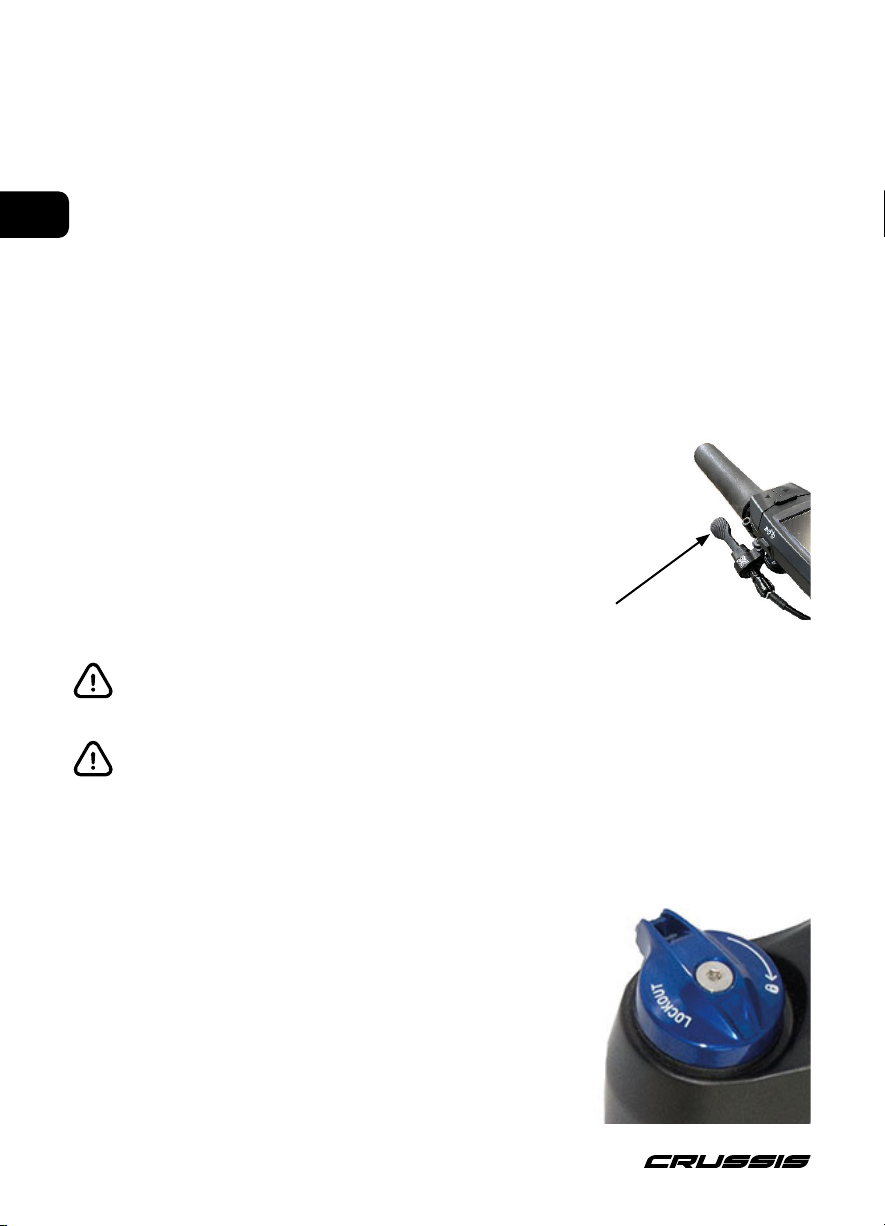
Rebound adjustment
Rebound damping controls suspension rebound speed after compression. Suspension rebound
speed affects wheel contact with the ground, which affects control and efficiency. The shock should
rebound quickly enough to maintain wheel traction without feeling 'bouncy'. Too much rebound
damping will not allow the shock to rebound quickly enough for the next bump. To increase rebound
damping, rotate the knob clockwise. To decrease rebound damping, rotate the knob counter-cloc-
kwise.
ROCKSHOX Deluxe Select R 210x55
(e-Full 9.9, ONE-Full 9.9)
ROCKSHOX Deluxe Select+ RT 185x55
(e-Full 10.9-M, ONE-Full 10.9-M)
116
EN
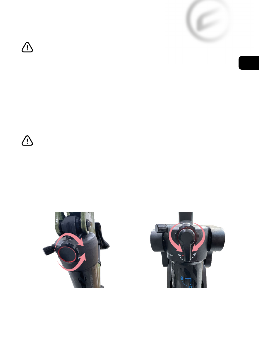
Threshold adjustment (T) (only e-Full 10.9 and ONE-Full 10.9)
The Threshold, or 'Pedal', setting prevents
the shock from compressing until moderate
impact or downward force occurs.
Use the Threshold setting to increase
pedaling efficiency on flat, rolling, and
smoother terrain.
To activate the Threshold setting, rotate the lever, or actuate
the remote, to the threshold position indicated on the shock.
The Lockout setting prevents the shock from compressing until significant impact or downward
force occurs. The shock will compress when force exceeds damper blow-offcircuit resistance. Use
the Lockout setting for maximum pedaling efficiency on smooth or rolling terrain. Rotate the lever,
or actuate the remote, to lock and unlock the compression damper.
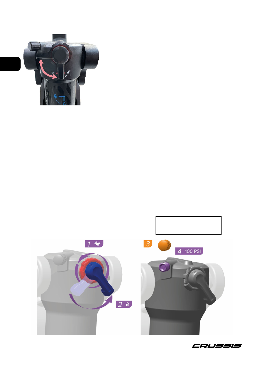
Adjusting the rear shock absorber
Suspension sag can be used to set the proper suspension spring rate for the rider. Sag is the amount
(percentage) the suspension compresses when the rider, including riding gear, is seated on the bi-
cycle in the riding position. Setting proper sag allows the wheels to maintain traction without using
too much travel reserved for shock absorbtion. More sag increases small bump sensitivity, while less
sag decreases small bump senstivity. Set spring sag before making any other tuning adjustments.
Set Sag - Air Shocks
Maximum permissible
pressure
360 psi
117
EN
Compress the shock once more to equalize air
pressure.
Pressurize the shock (PSI) to the equivalent of
the rider's total weight (lbs), including gear.
Example: 160 lbs/73 kg = 160 PSI/11 bar
Remove the pump.

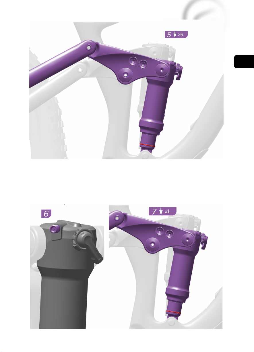
118
EN
Gently step offthe bicycle without compressing the shock.
Note the sag percentage where the o-ring stopped.
Correct sag percentage for Solo Air shocks is 25%. Correct sag percentage for DebonAir shocks is
30%. Sag can be set ±5% as preferred. Adjust pressure and retest sag as needed.
This manual is universal for the Panasonic GX series propulsion system.
All models of the Panasonic 9.9, 10.9 series are equipped with GX Ultimate motors.
System: Panasonic GX Ultimate
Maximum Torque: 95 Nm
Power: 250 W
Weight: 2.95 kg
Durability: IPX5
Pedal Sensor: Torque and Speed
While seated on the bicycle, have an assistant
slide the sag o-ring against the wiper seal.
With riding gear on, and an assistant holding
the bike, step onto the bicycle and lightly cycle
the shock two to three times.

119
EN
ELECTRIC BIKE SYSTEM
Motor activation is achieved through a torque (pressure, force) sensor integrated into the bottom
bracket. The torque sensor evaluates both the frequency and force of pedaling, transmitting this
information to the control unit, which then adjusts the motor's power output based on the force
applied while pedaling. The electric bike motor activates after approximately one pedal rotation and
deactivates after 1-2 seconds of pedal interruption. The motor disengages when a speed of 25 km/h
is reached and reactivates when the riding speed falls below this threshold. This complies with all
European standards, maintaining the classification of a bicycle. The electric bike is equipped with an
LCD panel that controls the electric assist. The display (controller) allows you to select different assist
modes ranging from OFF to HIGH. The highest assist mode is HIGH, while the OFF mode operates
without electric motor assistance. The LCD panel also features a "walk assist" function, enabling
the bike to reach speeds of up to approximately 6 km/h without pedal assistance. The walk assist
function aids in pushing or starting the bike and is not intended for continuous riding.
Optional Riding Programs:
[HIGH] *1Strong motor assistance is provided on flat roads and uphill roads.
[AUTO] *1Motor assistance automatically adjusts based on road conditions.
[STD] *1Moderate motor assistance is provided on flat roads and uphill roads.
[ECO] *1Slight motor assistance is provided on flat roads and uphill roads.
[OFF] *1No motor assistance.
*1Motor assistance may vary based on weather conditions, road conditions, bike condition, or
riding style.
The motor assistance modes are graduated, ranging from ECO (lowest assistance) to HIGH
(highest assistance), assisting up to a speed of 25 km/h. The torque sensor conveys pedaling
force information, with the electric motor providing more assistance as you pedal harder.
Walk assist: the bike travels at speeds of up to approximately 6 km/h and assists in starting
or pushing. This function is not intended for continuous riding! The speed and power of
the walk assistant depend on the selected gear ratio (larger chainring for lower speed but
greater force, suitable for uphill - smaller chainring for higher speed but less force, suitable
for flat terrain). To ensure proper walk assist function, it is recommended to use smaller
chainrings.
BATTERY INFORMATION
Currently, the most commonly used batteries are lithium-ion (Li-ion) batteries. The main advantage
of these batteries lies in their low weight and long lifespan. Li-ion batteries have very low self-dis-
charge rates. From the first charge, it's important to keep the battery within its operational cycle (dis-
charging/charging). Even when not in use, the battery will experience natural self-discharge, which is
normal. We recommend regularly recharging the battery, even if the electric bike is not being used,
approximately once a month, and storing it at a charge level of 60-80% capacity. Otherwise, there's
a risk of damaging the battery, which could lead to reduced range or, in more severe cases, comple-
te malfunction. Regular recharging extends the battery's lifespan. Before the first use, we suggest
fully charging the battery. As Li-ion batteries do not have a memory effect, they can be recharged
at any time. Maximum capacity is typically reached after about 5-10 charge cycles. Keep the battery
in a charged state and recharge it after each ride, rather than waiting until just before the next ride.
Li-ion batteries are 100% recyclable. You can return the battery to any collection point or directly to
the dealer. The battery is recharged using the supplied charger at 230/240V, and the charging time
is approximately 5-9 hours (depending on battery capacity and discharge level). During charging, the
battery can remain on the electric bike or be removed. To remove the battery, turn the key and then
extract it. The battery has an IP X5 rating.
120
EN
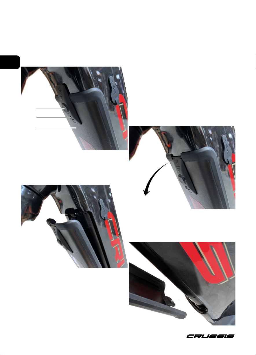
Frame battery with cover - fully integrated 720Wh
Removing the Battery Cover
Before removing the battery, you need to take offthe battery cover (1), which you do by pressing
and holding the button (2) on the battery cover (1) towards the bike and then sliding the entire latch
(3) as shown in the image below towards the motor. Swing open the cover (1) as shown below and
remove it towards the fork, releasing the latch (4).
When fitting the cover, proceed in reverse.
First, attach the cover latch (4), then close the
cover, press the latch button (2) towards the bike
and slide the entire latch towards the handlebars.
(2)
(3)
(1)
(4)
illustrative images
121
EN
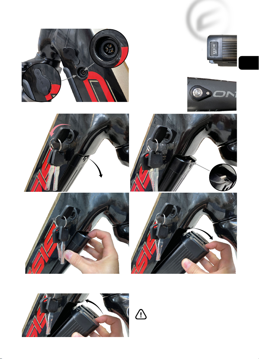
Removing the battery from the frame
(2)
(1)
By pressing the
safety latch,
you release
the battery.
The battery will pop out.
When inserting the battery into the frame, follow the reverse procedure of removal. First, attach
the connector, then securely snap the battery into the frame.
(1) Battery Charging Connector
(2) Opening with rubber cover in
the frame for connecting the
charger to the battery
(3) Battery Indicator,
power on/offbutton
(4) Power on/offbutton
on the frame
When removing/inserting the battery,
hold it with both hands.
Insert the key
and turn it
to the left
Safety latch
Remove the
battery.
r
in
(3)
(4)
Illustrative images
(4)
122
EN
Always turn offthe electric bike system before charging the battery! Never submerge the
battery in water (any liquids), do not store it in a damp environment, and do not disassemble
it. Before each ride, please ensure that the battery is properly seated and locked in place.
To turn on the battery in the bike, press the power button (4) on the upper frame tube briefly. The
button will blink several times and then remain illuminated. To turn offthe battery, press and hold
the power button (4) again until it turns off. The light signal from button (4) is only for indicating
whether the battery is in operation or not; it does not indicate the battery charge level. For that
purpose, refer to the battery indicator, but it is not visible when the battery is inserted in the frame.
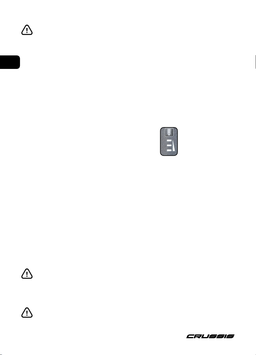
By briefly pressing button (3) on the battery, you can turn on the battery outside of the electric bike.
The LEDs on the battery will briefly illuminate, indicating the current battery charge level.
100 - 99% All 3 LEDs are lit.
98 - 67% First 2 LEDs are lit, and the third LED blinks.
66 - 34% First LED is lit, second LED blinks, and the
third LED is off.
33 - 0% First LED blinks, and the other LEDs are off.
The first LED is red, the others are green.
The representation of the battery charge level on the control panel is for reference only. If the motor
loses its smooth operation and runs intermittently, the battery capacity is too low. In this case, it is
necessary to turn offthe electric propulsion system. Continue riding without motor assistance and
ensure battery recharging.
To turn offthe battery, press and hold the button for approximately 3 seconds until the LEDs go off.
When inserting the battery into the electric bike, it will always turn on automatically. If you do not
intend to use the electric bike immediately, we recommend turning offthe battery by pressing and
holding the power button on the bike frame or, if the battery is removed from the frame, by pressing
and holding the battery button.
The behavior of the battery LED indicator may vary depending on the battery firmware. When
charging the battery on the bike, do not turn on the display. If you turn it on during charging,
it will automatically turn offafter about 3 seconds.
The representation of the battery charge level on the display is for reference only. In case
of excessive battery overheating, it will automatically shut down. The battery is protected
by a temperature sensor. Once the battery cools down to operational temperature, you can
continue riding. Battery heating is a common phenomenon related to its operation. We re-
commend keeping the battery keys separate to avoid carrying all of them on a single keyring
in case of loss.
The numbers are not
depicted on the battery;
they are only used to
specify the order of the
LEDs.
3
2
1

123
EN
The battery must be turned on before charging, so please turn on the battery. Connect the charger
to the battery and then to the power outlet. Once the charger is connected to the electrical outlet,
the red LED indicator on the charger will light up, indicating the start of the charging process. Du-
ring the charging process, the LED indicator on the frame battery will behave as described on the
previous page of this manual. At the end of the charging process, all three LED indicators will light
up, indicating that the battery is fully charged to 100%. If the LED indicator on the charger remains
red after charging, it means cell balancing is occurring. After cell balancing, the LED indicator on the
charger will turn green again. Only at this point is the battery fully charged and ready for use. The
duration of cell balancing will increase based on the battery's age. The behavior of the LED indicators
on the frame battery may change after a firmware update. We recommend performing the charging
process, including cell balancing, at least every third charge. The time to charge the battery to 100%
is between 5 to 9 hours depending on the level of discharge and battery capacity. After completing
the charging process, first disconnect the charger from the electrical outlet, and then from the batte-
ry. Interrupting the battery charging process will not damage it. The battery is of the Li-ion type, with
a nominal voltage of 36V, charging at 42V, and fully charged at 42V.
Charge the battery at room temperature (approximately 20°C). When charging, always
supervise the charging battery (e-bike). Charging the battery at temperatures below 10°C and
above 40°C can seriously damage the battery. Only use the charger provided with the e-bike
for battery charging. The battery is sensitive to precise charging; using a different charger
may result in battery or other e-bike component damage. In case the charger (or power
cable) is damaged, never connect it to the electrical outlet. Before charging, ensure that the
battery is turned on, and the e-bike system is turned off!
Battery connection
plug
LED indicator
mains plug
Illustrative image connector for connection to the charger
This charger is only suitable for charging Panasonic electric bike batteries with a capacity of 720 Wh.
Charging
This manual suits for next models
3
Table of contents
Other CRUSSIS Bicycle manuals


