INTERFACING SOLUTIONS
RVCCH-75K
REAR-VIEW CAMERA & FORCE RVC
INTEGRATION INTERFACE
FOR CHRYSLER & JEEP VEHICLES 2014-UP
www.cruxinterfacing.com4
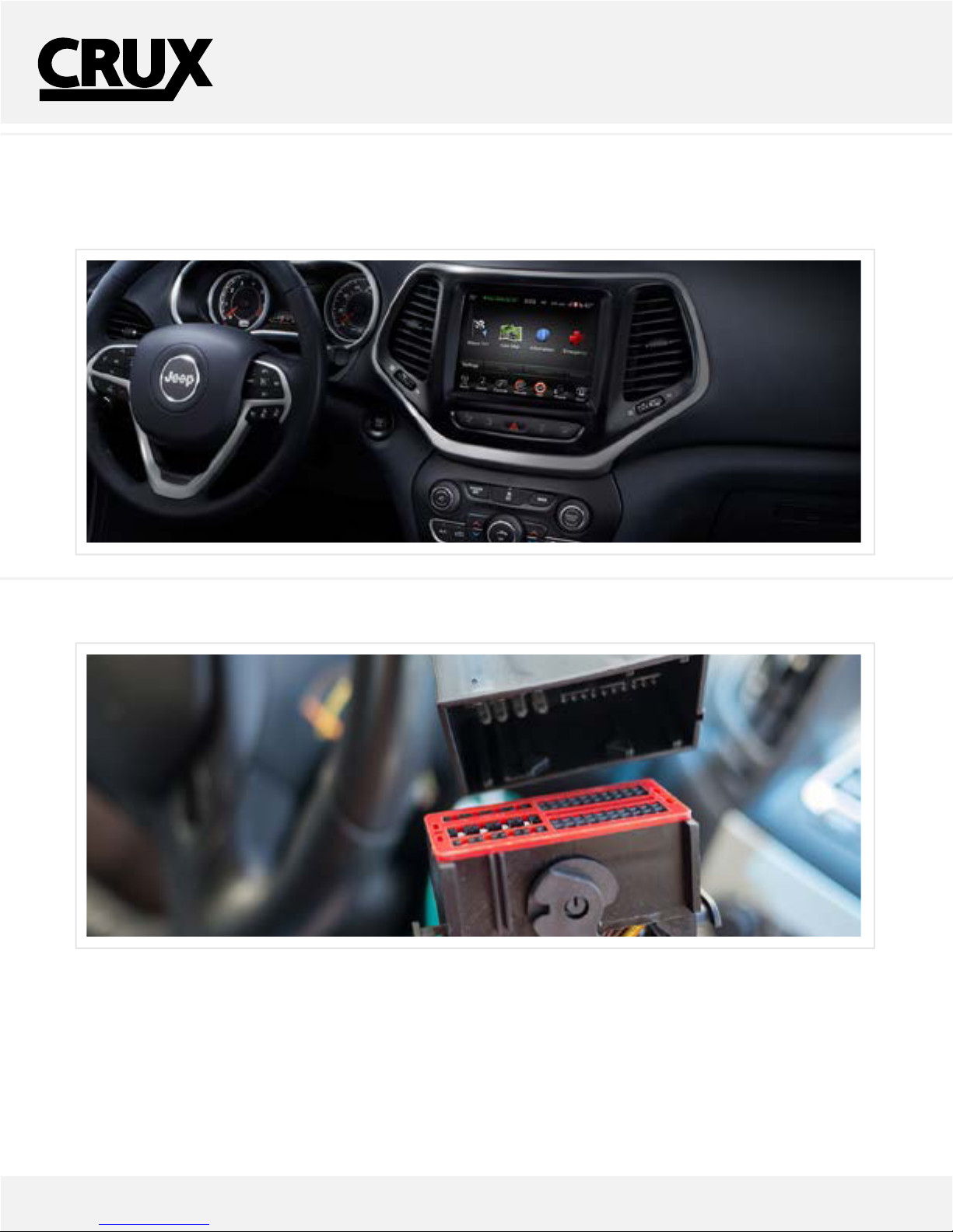
CONNECTING THE INTERFACE
Follow these steps to properly install the CAN module
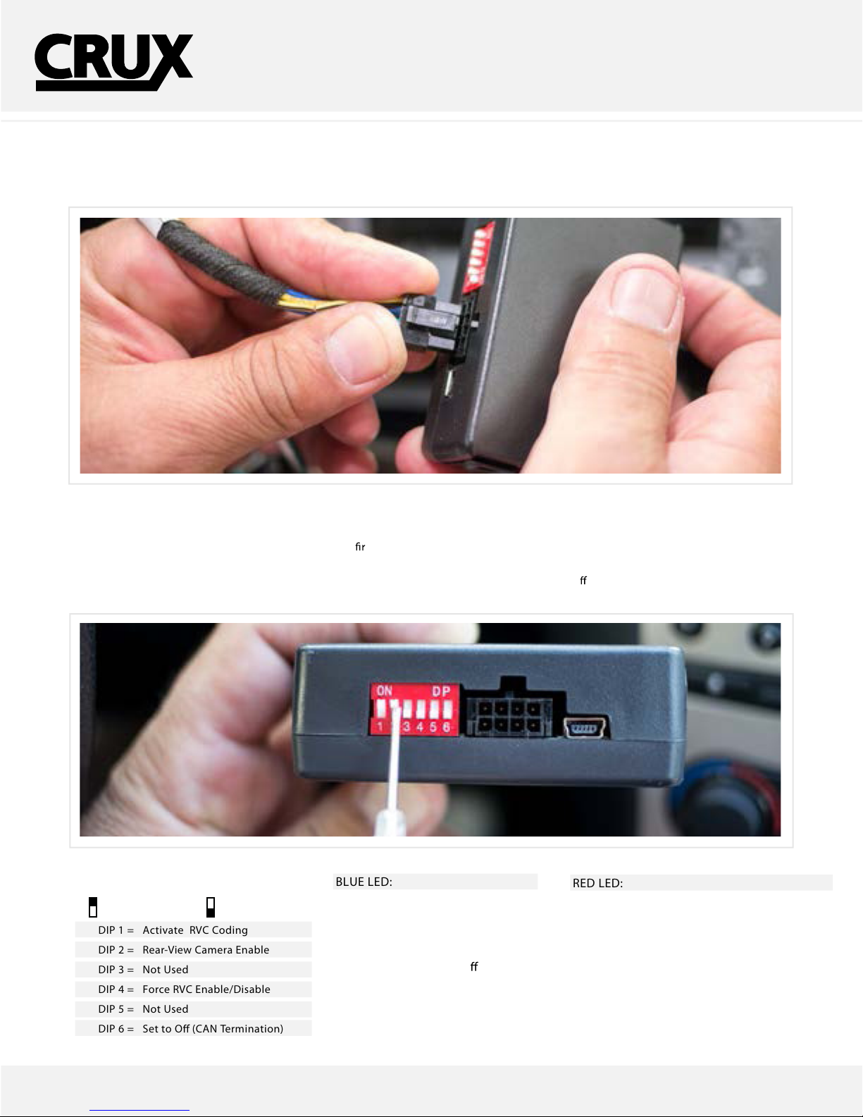
Step 3 - Connect the 8-Pin connector into the module.
Step 4 - After connecting the module, set dip switchesinthe following order to activate the Rear-View Camera.
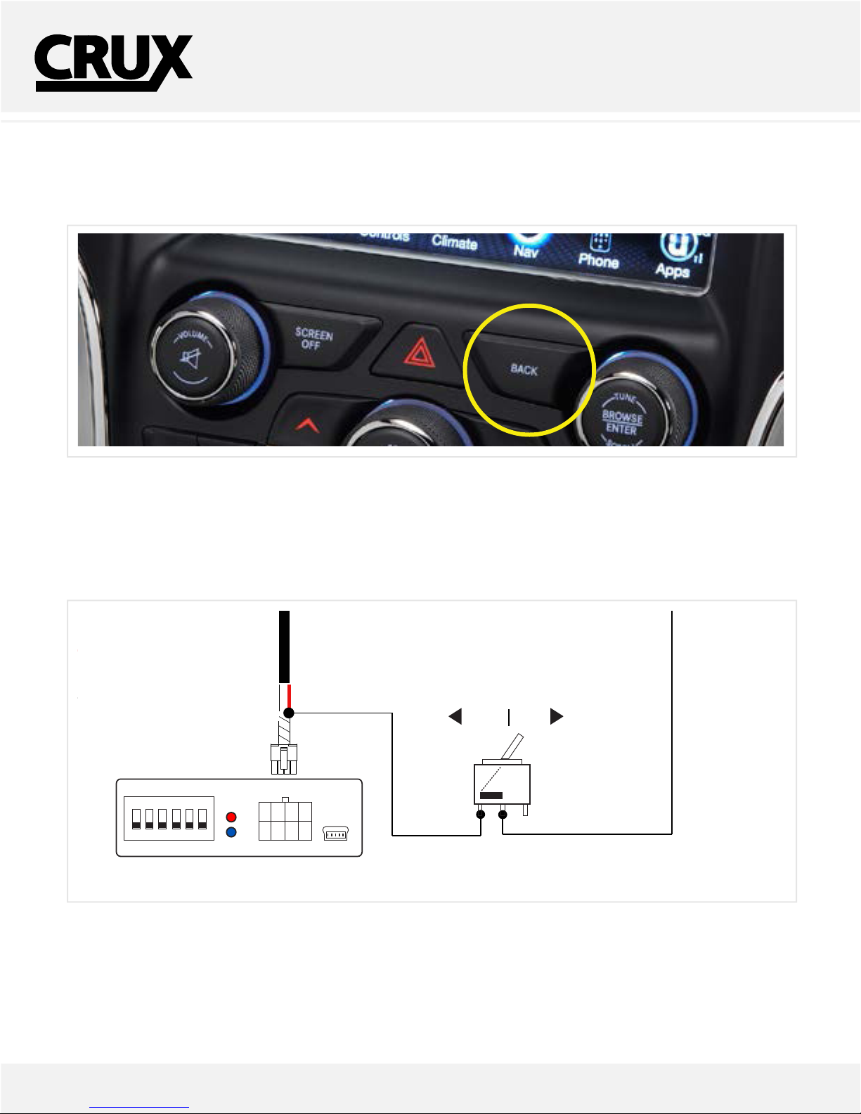
1. Place the key to the ON position, then turn on the Radio and listen to any source.
2. On the module, Set dip switch number 1 to “ON” st. (This activates Coding)
3. Now set dip switch number 2 to “ON” to activate the Rear-View Camera input.
4. Wait for the Radio to reset, may take up to 1 minute. DO NOT interrupt or turn the key to the o position. Please wait for reboot.
5. Test the Reverse Gear to verify coding is successful. (If not please disconnect module and retry the steps exactly).
DIP SWITCH DESCRIPTION
Set on the 8-Pin module.
DIP 1 = Activate RVC Coding
DIP 2 = Rear-View Camera Enable
DIP 3 = Not Used
DIP 4 = Force RVC Enable/Disable
DIP 5 = Not Used
DIP 6 = Set to O (CAN Termination)
UP=ON DOWN=OFF
LED INDICATORS
BLUE LED:
SOLID = BUS RECOGNIZED
OFF = SLEEP MODE
BLINKING = SEARCHING FOR BUS
The Blue LED will shut o when
the car enters sleep mode.
LED INDICATORS
RED LED:
FAST BLINKING = CODINGIN PROGRESS
ON = CODING COMPLETE
OFF = CODING REMOVED/ NO CODE
SLOW BLINKING = CODING ERROR
TROUBLESHOOT:
IF THE RADIO DOES “NOT TURN ON” OR FREEZES THE
SCREEN WHEN ON, PLEASE PLACE DIP 6 TO ON.
rev.060115