CRYOMAGNETICS 4G Instruction Manual

1006 Alvin Weinberg Drive
Oak Ridge, Tennessee 37830
Phone: (865) 482-9551 Fax: (865) 483-1253
https://www.cryomagnetics.com
WARNING!
DO NOT ATTEMPT TO OPERATE THIS EQUIPMENT BEFORE
THOROUGHLY READING THIS INSTRUCTION MANUAL.
OPERATING INSTRUCTION MANUAL
FOR THE
4G
MAGNET POWER SUPPLY
Issue Date: 02/20/2020
Rev. 9.3


CE
MANUFACTURER'S DECLARATION OF CONFORMITY
In accordance with ISO/IEC 17050-1
Manufacturer's Name: Cryomagnetics, Inc.
Manufacturer's Address: 1006 Alvin Weinberg Drive
Oak Ridge, TN 37830
Declares the product
Product Name: 4G Superconducting Magnet Power Supply
Model Numbers: 4G-100, 4G-150s, 4G-200s, 4G-100/100
Product Options: All Options
Conforms to the following Product Specifications:
Safety: EN61010-1 + Amendment 1
EN61326-1
EMC: EN55011 Conducted Emissions
EN55011 Radiated Emissions
EN61000-4-2 ESD Air Discharge, 2kV, 4kV, 8kV
EN61000-4-2 ESD Contact Discharge, 4kV
EN61000-4-3 Radiated Immunity 3V/m
EN61000-4-4 EFT 500V, 1kV, 2kV
EN61000-4-5 Surge 500V, 1kV L-L
500V, 1kV, 2kV L-G
EN61000-4-6 Conducted Immunity 10Vrms, 20Vrms
EN61000-4-8 Power Freq. Magnetic Field, 30A/m
EN61000-4-11 Voltage Dips and Interrupts
Application of Council Directives:
The product complies with the requirements of the Low Voltage Directive
2014/35/EU and the EMC Directive 2014/30/EU.
D.M. Coffey, President
Cryomagnetics, Inc
Oak Ridge Tennessee February 20, 2020


1. INTRODUCTION .................................................................................................................................... 1
1.1. DESCRIPTION .......................................................................................................................................... 1
1.2. FEATURES .............................................................................................................................................. 2
1.3. SPECIFICATIONS....................................................................................................................................... 5
2. INSTALLATION ...................................................................................................................................... 7
2.1. LINE VOLTAGE AND FUSES ......................................................................................................................... 7
2.2. MOUNTING ............................................................................................................................................ 7
2.3. ENVIRONMENT........................................................................................................................................ 7
2.4. TERMINAL STRIP CONNECTIONS.................................................................................................................. 8
2.5. POWER OUTPUT TERMINALS ..................................................................................................................... 9
2.6. MAINTENANCE........................................................................................................................................ 9
3. SETUP AND OPERATION ..................................................................................................................... 11
3.1. SETTING MAGNET PARAMETERS............................................................................................................... 11
3.2. SETTING CHARGE RATES ......................................................................................................................... 12
3.3. SETTING LIMITS..................................................................................................................................... 12
3.4. ENERGIZING THE MAGNET....................................................................................................................... 12
3.5. DISCHARGING THE MAGNET .................................................................................................................... 13
3.6. FAST SWEEPING .................................................................................................................................... 14
3.7. POWER FAIL MODE ............................................................................................................................... 14
3.8. MAGNET QUENCH................................................................................................................................. 15
4. DISPLAYS AND MENUS ....................................................................................................................... 17
4.1. NORMAL OPERATING DISPLAYS ................................................................................................................ 17
4.2. DISPLAY FIELD DESCRIPTIONS................................................................................................................... 19
4.3. KEYPAD OPERATION............................................................................................................................... 21
4.4. MENUS ............................................................................................................................................... 22
4.5. ORGANIZATION ..................................................................................................................................... 22
4.6. GENERAL MENU FEATURES ..................................................................................................................... 23
4.6.1. Limits Menu .............................................................................................................................. 24
4.6.2. Rates Menu............................................................................................................................... 25
4.6.3. Magnet Menu ........................................................................................................................... 26
4.6.4. General Menu ........................................................................................................................... 28
5. INTERFACING ..................................................................................................................................... 31
5.1. USB COMPUTER INTERFACE .................................................................................................................... 31
5.2. IEEE-488.2 COMPUTER INTERFACE.......................................................................................................... 31
5.3. ETHERNET INTERFACE ............................................................................................................................. 32
6. THEORY OF OPERATION ..................................................................................................................... 33
6.1. CIRCUIT DESCRIPTION............................................................................................................................. 33
7. LIMITED WARRANTY POLICY .............................................................................................................. 35
Appendix A: Factory Calibrations and Certification ............................................................................................... 37
Appendix B: Computer Interface Command Reference......................................................................................... 39
Appendix C: Shared Output Leads ......................................................................................................................... 57
Appendix D: Shut-down Input................................................................................................................................ 59
Appendix E: Paralleling Power Modules ................................................................................................................ 61
Appendix F: Firmware Upgrading .......................................................................................................................... 63
Appendix G: Shim Supply Option ........................................................................................................................... 77

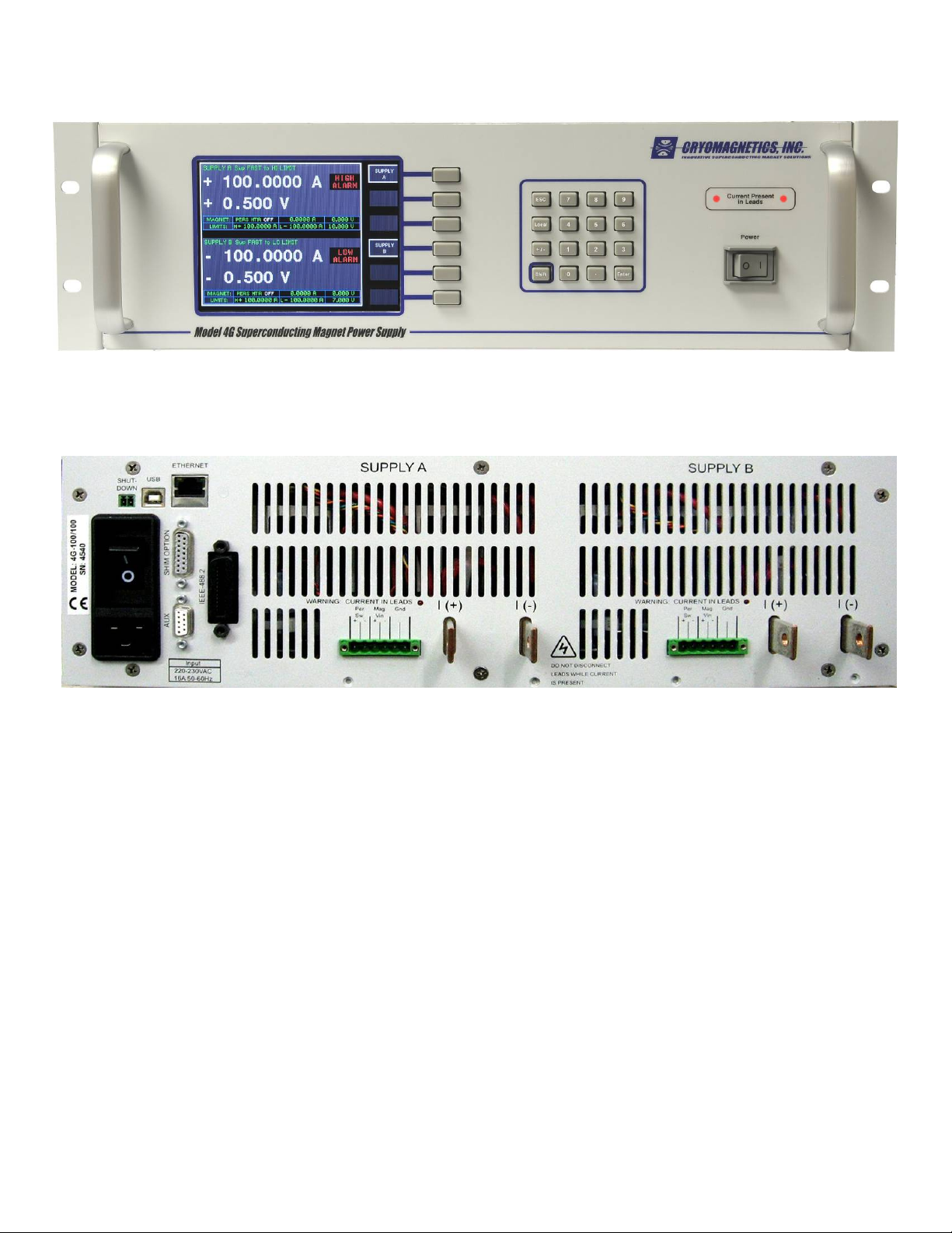
Figure 1: Front View, Dual Supply........................................................................................................ 2
Figure 2: Rear View, Dual Supply ......................................................................................................... 2
Figure 3: Rear Panel Terminal Strip ..................................................................................................... 8
Figure 4: Normal Operating Display, Single Supply........................................................................ 17
Figure 5: Keypad Layout ...................................................................................................................... 21
Figure 6: Menu Organization ............................................................................................................... 22
Figure 7: General Setup Menu............................................................................................................. 23
Figure 8: Limits Menu ........................................................................................................................... 24
Figure 9: Magnet Parameters Menu ................................................................................................... 26
Figure 10: General Power Supply Setup Menu ................................................................................ 28
Figure 11: Parallel Supply Connections ............................................................................................ 61
Figure 12: Superconducting Magnet with Shims............................................................................. 77
Figure 13: Superconducting Magnet with Multiplexed Shim Persistent Switch Heaters ......... 79
Figure 14: SHIM Mode Operating Display ......................................................................................... 81
Figure 15: Shim Setup Menu ............................................................................................................... 82
Figure 16: Shim Edit Menu................................................................................................................... 83
Figure 17: Shim Output Connector .................................................................................................... 84

Symbols and Abbreviations
Warning – Danger of electrical shock
Protective Earth Ground
A Amperes
°C degrees centigrade
°F degrees Fahrenheit
Hz Hertz
kg kilograms
kG kilogauss
mA milliamperes
mV millivolts
T tesla

Cryomagnetics Model 4G Operating Instruction Manual
1
1. Introduction
1.1. Description
The 4G Superconducting Magnet Power Supply is an advanced instrument designed specifically for
powering superconducting magnets. It is a true four-quadrant power supply, meaning it is capable
of operating with positive current / positive voltage (sourcing power), positive current / negative
voltage (sinking power), negative current / positive voltage (sinking power), and negative current /
negative voltage (sourcing power). The supply allows the user to generate smooth sweeps through
zero current for performing hysteresis loop experiments or other research requiring smooth
magnetic field reversal.
The 4G is available in several configurations using one or two power modules. Power modules are
available as 100A, 150A, and 200A units. This architecture allows the 4G to be configured as a
single 100A, 150A, 200A, or dual 100A unit. Older dual units may be paralleled externally by the
user to provide the full 200A current capability to a single load, but this requires special operational
considerations (see Appendix E). All 4G units are capable of delivering up to ±10 volts of output
voltage. An easy-to-use menu system is provided to allow the operator to set the supply up using
the parameters of his/her particular magnet. Most of the supply operating parameters may be
changed or queried through USB and IEEE-488 interfaces.
Power supplies used for energizing superconducting magnets have unique requirements placed
upon them. The supplies are used to source energy to magnets which can have a wide range of
inductances (mH to kH). In addition, the magnet load can range from a nearly pure resistance to a
nearly pure inductance – and everything in between. This places demands on the supply that are
far beyond what a typical power supply used for bench top electronics would see. The supply will
experience the challenges of sinking energy when a magnet is discharging. At the same time, the
potential exists for either the magnet or power supply to be damaged in the event of a power failure
or magnet quench. The 4G’s advanced circuitry enables it to handle virtually any scenario
encountered in superconducting magnet operation in stride. The design of the 4G makes it a low
noise, highly efficient supply – and one that is proven stable even on the most sensitive
superconducting magnets. Versatile programmability allows the user to specify several different
sweep rates for different current ranges of the magnet – making it possible to sweep a magnet
slower in a particular range if it is more sensitive there, without user intervention
Cryomagnetics Model 4G Operating Instruction Manual
2
1.2. Features
The 4G has a wide range of features available:
True Four-Quadrant Operation. The supply can provide positive or negative output current
along with positive or negative voltage. This gives it the ability to smoothly sweep through zero
current without the need for current reversing switches or pauses.
User Friendly Menus. The 4G has intuitive menus to display and enter operating parameters.
It can be set up in minutes, and changes during daily operation are simple and quick.
Easy to Read Display. The high quality 5 1/4” color LCD can be read at a glance. The current
is displayed in a large font that can be read even from across the lab.
Figure 2: Rear View, Dual Supply
Figure 1: Front View, Dual Supply

Cryomagnetics Model 4G Operating Instruction Manual
3
High Stability ±10 Volt; ± 100A, ± 150A, and ± 200A Outputs. The 4G provides quiet, stable
output power thanks to its low noise design, precision current monitoring, and control circuits.
Power Fail Magnet Discharge. Should a power failure occur during operation of the magnet,
the supply will switch to a “Power Fail” mode where it will discharge the magnet at a low
voltage. If power is restored, the user can intervene to stop the discharge and re-energize the
magnet. “Power Fail” mode is a convenient feature of the 4G since it allows the user to simply
turn off the power switch for the unit at the end of the day to discharge a magnet.
Independent Upper and Lower Current Limit Set points. Independent current limits allow
sweeping between two set points without having to re-enter the menu and change limits.
PID-Controlled Sweeping. A PID inside the power supply’s control circuits allows smooth
sweeping between set points without the need for magnet voltage taps.
Adjustable Settings During Sweep. The menu system can be entered at any time during
operation of the supply to change parameters. While in the menu, the display continues to
update the user as to the status of the supply/magnet.
Computer Interfacing. USB and IEEE-488 interfaces are standard. Through either interface, a
comprehensive set of monitor and control commands is available. The IEEE-488 interface
conforms to the IEEE-488.2-1992 standard.
LabVIEWDrivers. Virtual Instrument drivers compatible with National Instruments
LabVIEWare available for Cryomagnetics’ instrumentation through Cryomagnetics’ website.
Persistent Switch Heater Supply. A persistent switch supply is built into the 4G.
Remote Shut-down Input. A signal can be provided by the user to the 4G which tells it to
discharge the magnet. This can be used to lock out operation of the magnet when helium gets
too low or when some other user-defined event occurs.
Quench Detection and Protection. The 4G is fully protected from damage due to a quench. In
addition, if a quench is detected the 4G will give an audiovisual indication of the quench. The
current readings leading up to the quench can be displayed. Since quench detection activates
on observed current transients, it must be disabled if automatic recovery is desired from
abnormal conditions such as those encountered in several of the CE qualification tests.

Cryomagnetics Model 4G Operating Instruction Manual
4
This Page Intentionally Left Blank

Cryomagnetics Model 4G Operating Instruction Manual
5
Specifications
Common Specifications Current Voltage
DC Output: See model specific specs ± 10 V
Output Power See model specific specs
Ripple and noise 20 uA rms 10 mV rms @ 100A
Stability (drift) at 25 ± 1C: ± 3mA / °C ± 0.01% Vmax
Display Resolution: 0.1 mA 1 mV
Display Update Rate: 2Hz
Output Current Granularity: 0.1 mA 5 mV
Sweep Rate Resolution: 0.1 mA/sec
Source effect (line regulation for any line
change within the rated line voltage): 0.005% Imax 0.05% Vmax
Load effect (load regulation for a load change equal
to max. voltage in constant current mode or
max. current in constant voltage mode): 0.01% Imax 0.01% Imax
Output Protection: Protected from damage due to quench
Persistent Switch Heater 0-125mA 0-12V
AC Input: 220-230V AC., 50-60 Hz, 9.5A max
Circuit Breakers: 16A, 240V AC., slow blow
Operating Temperature: 15 °C to 35 °C
Relative Humidity 10% to 95%, non-condensing
Over-Temperature Protection: Unit will limit discharge power to prevent
overheating.
Overall Dimensions (excluding front handles): 483 mm W X 133 mm H X 533 mm D
USB interface: USB 1.1/2.0 Full-Speed
IEEE-488 interface: IEEE-488.2-1992 Standard
Ethernet: IEEE-802.3 10/100 BASE-T
Shut-down Input: +5V, +24V, or switch closure signaling
Model Specific Specifications
Max Current Max Output Power Weight (lbs/kg)
4G-100 100A 1000W (10V @ 100A) 29.0/13.2
4G-150s150A 1500W (10V @ 150A) 43.2/19.7
4G-200s 200A 1600W (8V @ 200A) 43.2/19.7
4G-Dual (100/100) 100A/100A 800W/800W (8V @ 100A) 43.2/19.7
The 4G is designed to operate per the specifications in this table and the instructions provided in
this manual. Other use may impair the safety protections provided by the equipment.

Cryomagnetics Model 4G Operating Instruction Manual 6
This Page Intentionally Left Blank

Cryomagnetics Model 4G Operating Instruction Manual 7
Installation
The following section outlines information concerning the installation and setup of the 4G supply. As
with any equipment purchase, the user is strongly encouraged to inspect the power supply for
shipping damage immediately upon receipt. Proper power and ground connections should be made
using the appropriate codes and practices. Should the 4G require return to the factory due to
shipping damage or for servicing, contact Cryomagnetics or an authorized service representative for
instructions and a return authorization number. The 4G is delivered fully tested, calibrated, and
ready to operate. This includes configuring appropriate setup values if the supply is purchased with
a magnet system.
1.3. Line Voltage and Fuses
The 4G is fused for operation using 220-230V AC., 50-60 Hz input power by a 16A circuit breaker
incorporated in the power entry module. Never use an ungrounded power cord for line power.
It is strongly recommended that AC power provided to the 4G be protected with a Ground Fault
Interrupter (GFI) and a surge suppressor. If the unit is operating in an area subject to power failures
or brownouts, the user may wish to install an Uninterruptible Power Supply (sine wave) to minimize
the chance of inadvertently discharging or quenching the magnet due to line effects.
1.4. Mounting
The 4G is compatible with all standard 19-inch wide rack cabinets. Due to the instrument’s weight, it
is recommended that rails be located beneath the supply to prevent bending of the supply mounting
brackets. Adequate ventilation is essential to the 4G. An unobstructed air path should be available
at the ventilation slots in the rear and side panels of the instrument and at the fan outlets to avoid
overheating.
1.5. Environment
The 4G is designed for operation in free air, non-condensing atmospheres within a temperature
range of 15 to 35C (59 to 95F). It has been designed primarily for laboratory use, so harsh
environments of dust or corrosive materials could result in eventual damage. A filtered enclosure is
recommended for operation under these conditions.
Cryomagnetics Model 4G Operating Instruction Manual 8
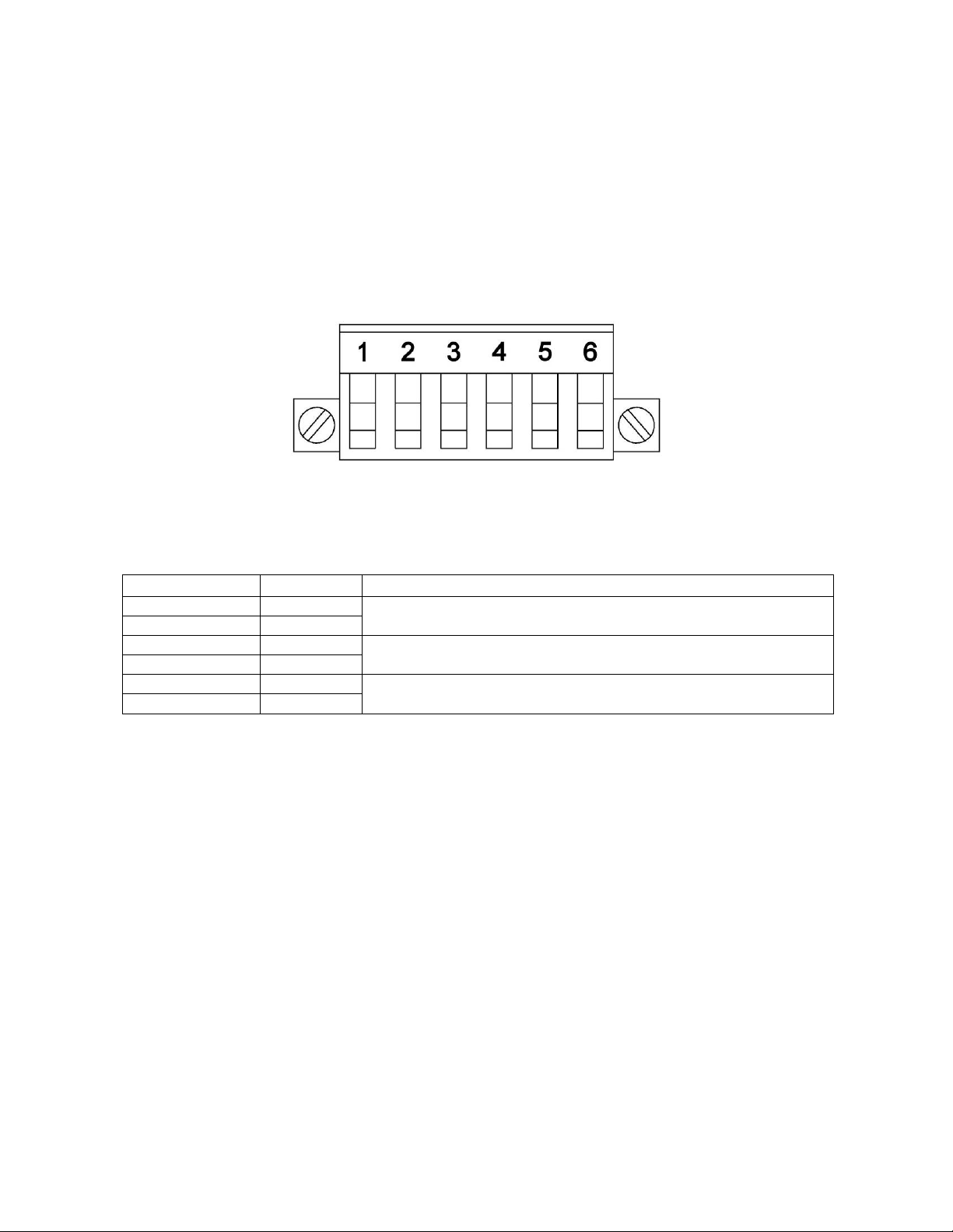
1.6. Terminal Strip Connections
The rear panel terminal strip of the 4G provides an interface for all analog input and output signals
for the 4G. The terminal strip is shown in Figure 3. Table 1 outlines the definition and function of
each terminal pair. A cover is provided to prevent electrostatic discharge damage to the electrical
connections. A terminal strip is present for each installed power module.
Table 1: Terminal Pinout
Terminal #
Name
Function
1
Pers Sw +
Persistent Switch Heater Power Supply Output
2
Pers Sw -
3
Mag.Vin +
Magnet Voltage Taps – Input Signal to 4G from Magnet (optional)
4
Mag.Vin -
5
Ground
Ground connections for I/O Cable and Output Cable shields
6
Ground
Before making connections to the rear panel terminal strip, make sure the power to the 4G is OFF.
Shield cables must be used with shields connected to terminal 6 for CE compliance. Make all
connections using the appropriate wire size. The terminal strip is designed to accept AWG 24 – 12
(0.2 – 2.5 mm2stranded or 0.2 – 0.4 mm2solid) conductor. The ends should be stripped bare 7mm.
All connections should be isolated from instrument ground and from each other.
Figure 3: Rear Panel Terminal Strip

Cryomagnetics Model 4G Operating Instruction Manual 9
1.7. Power Output Terminals
The high current output terminals are located on the rear panel and are labeled I(+) and I(-). Make
sure the 4G power is OFF before attaching the terminals to the magnet power leads. Care should
be taken in attaching power leads to the magnet to ensure solid contact is made using a ¼-20 bolt
and nut on each terminal. Although quench protection is built into the 4G to prevent the occurrence
of high voltages, the magnet leads should NEVER be disconnected when current is present.
Potentially lethal voltage can easily occur due to the high inductance of superconducting magnets.
CAUTION – RISK OF ELECTRIC SHOCK
Note: Ferrite beads (Fair-Rite P/N 0444177081) must be installed on the output cables for
compliance with CE standards for RF conducted immunity. Cables must be shielded with their
shields connected to terminal 6 of the terminal block.
1.8. Maintenance
The 4G should be inspected periodically to verify that all connections are secure, fans are operating
properly, and ventilation openings are clear.
If cleaning is required, disconnect the power cord and clean the unit with a soft cloth dampened with
water.
The 4G does not contain user serviceable parts. If repairs should be required, contact the factory for
a repair authorization number, and return the supply to the factory for service to ensure the integrity
of the unit is maintained.

Cryomagnetics Model 4G Operating Instruction Manual 10
This Page Intentionally Left Blank

Cryomagnetics Model 4G Operating Instruction Manual 11
Setup and Operation
The 4G is designed specifically for operation with superconducting magnets. Before using the
supply to energize a magnet, certain parameters specific to the superconducting magnet being
used, desired charge rates, and operating current limits should be set. The following procedure is
recommended.
1.9. Setting Magnet Parameters
The first thing the user should set up is the magnet parameters. If this is a dual unit, select SUPPLY
A or SUPPLY B first. In the sweep menu, press [SETUP], then [MAGNET]. The display will show
the Magnet Parameters. If a persistent heater is being used, Persistent Heater Present should be
set to Yes. If the magnet to be energized is currently at zero field, the Persistent Mode Current
should be set to 0.0000A. If the magnet is already in persistent mode at some other known current,
this current can be entered instead. Be sure the polarity of the magnet current is entered correctly.
The maximum safe operating current for the magnet should be entered in the Maximum Current
Rating parameter position. The supply will not allow output current to exceed this value. Should the
user enter a Sweep Limit setting exceeding this value (in the Limits menu), the supply will only
sweep to the Maximum Current Rating value and indicate MAG LIMIT REACHED on the display.
The Gauss/Amp Ratio of the magnet may be entered in the Magnet Parameters setup if desired.
The 4G only uses this parameter if the Display Units is set to Field rather than Amperes. Setting
this parameter is not essential.
If the magnet to be energized is equipped with a persistent mode switch, the heater current
necessary to activate it should be entered in the Persistent Switch Heater (mA) field. The
persistent switch heater power supply is capable of sourcing up to 125 mA of output current at up to
12V.
If quench detection is desired, set Quench Detection to On.
Set the magnet's nominal inductance in the Inductance (H) field. If the supply was shipped with a
magnet, this field should already be set.
When done with the magnet parameters, press EXIT, then SAVE.

Cryomagnetics Model 4G Operating Instruction Manual 12
Setting Charge Rates
The charge rates for energizing the magnet should be entered through the Rates menu. The 4G
allows the user to set up to five different charge rates to be used in five current ranges, plus a fast
rate. This allows the user to specify a slower rate for a magnet when it is near its maximum rated
field.
From the sweep menu, press [SETUP], then [RATES]. Using the inductance of the magnet as a
guide, set the desired rates keeping in mind that the best (smoothest) sweeps of the magnet are
achieved when a 1V-2V margin is maintained relative to the supply’s voltage limit setting. The
charging voltage of the magnet is calculated by V = L di/dt, where the value of di/dt is the desired
sweep rate in amperes per second indicated in the Rates menu.
Once the rates and their respective current ranges have been set, press [EXIT] then [SAVE] to
accept the changes, or [DISCARD] to abort and ignore all changes. If the message 'VALUE TOO
LOW' appears, it means that the value in one of the “To” fields is lower than its corresponding
“From” field, when it should be greater.
1.10. Setting Limits
The desired operating current for the magnet is set in the Limits menu. The 4G allows the user to
enter two different limits – an upper and a lower – to enable smooth sweeps between two points.
The upper and lower current limits may be positive or negative, as long as the upper is more
positive than the lower.
From the Sweep menu, select [SETUP] then [LIMITS]. Use the arrow keys to select the appropriate
current limit and then enter the desired value. If changes to the voltage limit are desired, this can be
entered now.
If alarm operation is desired, change the Alarm HI Limit and Alarm LO Limit to the desired values.
This will result in alarm messages on the display when these values are exceeded. If the optional
relay outputs are in use, they can be enabled or disabled with the Alarm Relay Bypass setting. If
set to On, the outputs remain closed all the time.
When an alarm occurs, it can either reset automatically (when the current falls back within limits) or
require a button press. To automatically reset this, set Alarm Relay Autoreset to On.
Once the settings are made, press [EXIT] and [SAVE] to accept the changes (or [DISCARD] to
abort and ignore the changes).
1.11. Energizing the Magnet

Cryomagnetics Model 4G Operating Instruction Manual 13
Once the magnet parameters, charge rates, and limits have been set, the supply is ready to
energize the magnet. If the magnet has a persistent switch installed, go to the supply sweep menu
and energize the persistent switch heater supply by pressing [PERS HTR] then [CONFIRM HTR
ON]. Pressing either [CANCEL] or [ESC] will cancel turning the heater on. Wait for the magnet’s
persistent switch heater to warm before beginning a sweep.
Press [HI LIMIT] to begin energizing the magnet in the direction of the upper current limit.
Alternatively, the operator can press [LO LIMIT] to begin energizing the magnet in the direction of
the lower current limit. Once the appropriate current limit is reached, the 4G will hold that current.
To place the magnet into persistent mode, turn off the persistent switch heater supply by pressing
[PERS HTR] then [CONFIRM HTR OFF]. Pressing either [CANCEL] or [ESC] will cancel turning the
heater off. Wait for the persistent switch heater to cool before zeroing the current in the leads.
Once the magnet is in persistent mode, the current in the leads may be brought back to zero by
pressing the [Zero] key.
IMPORTANT
Be sure to zero the supply by pressing the [ZERO] key.
Pressing [LO LIMIT] will result in the supply sweeping to the
lower current limit rather than to zero.
Watch the magnet voltage while the supply begins to sweep toward zero to verify that the magnet
has indeed entered persistent mode. If no voltage is detected, press [Shift-ZERO] to bring the
supply back to zero output current at the fast sweep rate. When the supply reaches zero output
current, it will automatically switch to Standby mode.
1.12. Discharging the Magnet
To discharge a magnet that is in persistent mode, press the [Shift-HI LIMIT] or [Shift-LO LIMIT] to
quickly bring the supply output current back to the level of the locked in current in the magnet. Be
sure to bring the current back to the same polarity that was left in the magnet.
When the current limit is reached, the supply will stabilize and hold that current. From the main
supply sweep menu, energize the persistent switch heater supply by pressing [PERS HTR] then
[CONFIRM HTR ON]. Wait for the switch to fully warm before sweeping the magnet. To cancel
turning the heater on, press either [CANCEL] or [ESC].
Once the persistent switch is warm, sweep the magnet current back to zero by pressing the [ZERO]
This manual suits for next models
4
Table of contents


