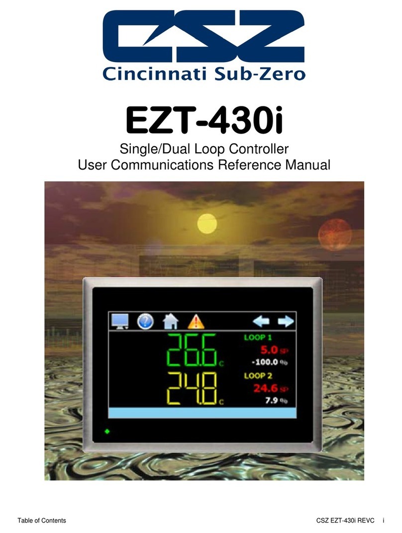
CSZ EZT-430i User manual

EZT-430i
Single/Dual Loop Controller
User Manual

EZT-430i User’s Manual
EZT-430i Preface
Safety Information in this Manual
Notes, cautions and warnings appear throughout this book to draw your attention to important operational and
safety information.
A “NOTE” marks a short message to alert you to an important detail.
A “CAUTION” safety alert appears with information that is important for protecting your equipment and
performance.
A “WARNING” safety alert appears with information that is important for protecting you, others and equipment
from damage. Pay very close attention to all warnings that apply to your application.
This symbol (an exclamation point in a triangle) precedes a general CAUTION or WARNING
statement.
This symbol (a lightning bolt in a lightning bolt in a triangle) precedes an electric shock hazard
CAUTION or WARNING safety statement.
Technical Assistance
If you encounter a problem with your EZT-430i controller, review all of your configuration information to verify
that your selections are consistent with your application: inputs; outputs; alarms; limits; etc. If the problem
persists after checking the above, you can get technical assistance by dialing 1 (513) 772-8810 or by faxing
your request to 1 (513) 772-9119, Monday thru Friday, 7:30 a.m. to 5:30 p.m. Eastern Standard Time. You
An applications engineer will discuss your application with you.
Please have the following information available:
• Complete Model #’s and/or Serial #’s for Component(s) in Question
• Complete Software Version #’s
• All Configuration Information
• All User Manuals
Warranty and return information is on the back cover of this manual.
Your Comments
Your comments or suggestions on this manual are welcome. Please send them to:
Telephone: +1 (513) 326-5252; fax: +1 (513) 326-5258
support@cszproducts.com

EZT-430i User’s Manual
TableofContents EZT-430iREVC i
1What is EZT-430i?.....................................................................................................1.1
1.1 Features...............................................................................................................................................1.1
2Installation.................................................................................................................2.1
2.1 Enclosure Guidelines...........................................................................................................................2.1
2.1.1 Locating the EZT-430i Touch Screen Interface.............................................................................2.2
2.2 Environmental Considerations.............................................................................................................2.2
2.3 Mounting Dimensions...........................................................................................................................2.2
2.3.1 EZT-430i Touch Screen Interface .................................................................................................2.2
2.3.2 EZT-430i Process Loop Controllers..............................................................................................2.4
3Wiring.........................................................................................................................3.1
3.1 Power Requirements............................................................................................................................3.1
3.1.1 Installing the Power-On Delay Relay.............................................................................................3.2
3.2 Connecting to the EZT-430i Interface..................................................................................................3.3
3.2.1 Process Loop Controller Communications....................................................................................3.4
3.2.2 User Serial Communications.........................................................................................................3.5
4Basic Operation.........................................................................................................4.8
4.1 OEM Configuration Options.................................................................................................................4.8
4.1.1 Loop 1/2 Monitor Mode..................................................................................................................4.8
4.2 Touch Screen Interface........................................................................................................................4.9
4.3 Menu Navigation................................................................................................................................4.10
4.3.1 Home Menu.................................................................................................................................4.11
4.3.1.1 Text Based Home Menu .......................................................................................................4.11
4.3.1.2 Icon/Slide Page Based Home Menu.....................................................................................4.12
4.3.2 Automatic Ramp/Soak Program Menu........................................................................................4.13
4.3.2.1 Text Based Program Menu...................................................................................................4.13
4.3.2.2 Icon/Slide Page Based Program Menu.................................................................................4.14
4.3.3 Device Settings Menu..................................................................................................................4.15
4.3.3.1 Text Based System Setup Menu ..........................................................................................4.15
4.3.3.2 Icon/Slide Page Based Device Settings Menu .....................................................................4.16
4.3.4 Offline Menu ................................................................................................................................4.16
4.3.4.1 Text Based Offline Setup Menu............................................................................................4.16
4.3.4.2 Icon/Slide Page Based Offline Menu....................................................................................4.17
4.3.5 Data Menu...................................................................................................................................4.18
4.3.5.1 Text Based Data Logging Menu ...........................................................................................4.18
4.3.5.2 Icon/Slide Page Based Log Menu.........................................................................................4.19
4.4 Notifications........................................................................................................................................4.20
4.5 Control Loops (Single Set point Operation).......................................................................................4.20
4.5.1 Single Loop View.........................................................................................................................4.21
4.5.2 Dual Loop View ...........................................................................................................................4.22
4.6 Event Control .....................................................................................................................................4.23
4.7 Process Monitoring ............................................................................................................................4.24
4.7.1 Charts..........................................................................................................................................4.24
4.7.1.1 Chart Setup...........................................................................................................................4.25
4.8 System Alarms...................................................................................................................................4.26
4.8.1 Alarm Monitor ..............................................................................................................................4.26
4.8.2 Alarm File.....................................................................................................................................4.27

EZT-430i User’s Manual
iiEZT-430iREVC TableofContents
5Automatic Ramp/Soak Program Operation ............................................................5.1
5.1 Entering a Ramp/Soak Program..........................................................................................................5.2
5.1.1 Setting Step Set Points and Time..................................................................................................5.3
5.1.2 Setting Step Set Point and Ramp Rate (single loop only).............................................................5.4
5.1.3 Setting Step Events.......................................................................................................................5.4
5.1.4 Setting Jump Steps .......................................................................................................................5.5
5.1.5 Setting the End Step......................................................................................................................5.6
5.1.6 Hold Back Operation .....................................................................................................................5.6
5.2 Starting an Automatic Ramp/Soak Program........................................................................................5.7
5.2.1 Hold/Resume Ramp/Soak Program Operation.............................................................................5.8
5.3 Monitoring Automated Ramp/Soak Program Operation......................................................................5.8
6Security......................................................................................................................6.1
6.1 Adding Users........................................................................................................................................6.2
6.2 Viewing Users......................................................................................................................................6.2
6.2.1 New Password Entry.....................................................................................................................6.3
6.3 Setting User Access.............................................................................................................................6.3
6.3.1 Security System User Access .......................................................................................................6.4
6.4 Setting Security Options.......................................................................................................................6.5
6.5 Audit Trail.............................................................................................................................................6.6
7Data Logging.............................................................................................................7.1
7.1 Selecting Points for Logging................................................................................................................7.2
7.2 Starting/Stopping Data Logging...........................................................................................................7.2
7.2.1 Calculating Log File Size...............................................................................................................7.3
7.3 Reviewing Historical Data....................................................................................................................7.3
7.3.1 History Plot Setup..........................................................................................................................7.4
7.3.2 Plotting Historical Data..................................................................................................................7.4
7.4 USB File Transfer.................................................................................................................................7.6
7.5 FTP Data Backup.................................................................................................................................7.8
7.6 Annotation............................................................................................................................................7.9
7.7 Add\View Digital Signatures...............................................................................................................7.10
8Device Settings .........................................................................................................8.1
8.1 Tuning ..................................................................................................................................................8.2
8.2 Alarms..................................................................................................................................................8.3
8.3 Setpoint Limits......................................................................................................................................8.4
8.4 Event Names........................................................................................................................................8.5
8.5 Navigation............................................................................................................................................8.5
8.6 Communication Settings......................................................................................................................8.6
8.7 Email ....................................................................................................................................................8.7
8.7.1 Email Address Entry......................................................................................................................8.7
8.7.2 Email Addresses............................................................................................................................8.8
8.7.3 Email Settings................................................................................................................................8.8
8.7.4 Email Message..............................................................................................................................8.9

EZT-430i User’s Manual
TableofContents EZT-430iREVC iii
9Offline.........................................................................................................................9.1
9.1 Power Recovery...................................................................................................................................9.2
9.2 Degrees C/F Units Selection................................................................................................................9.3
9.3 Clock Settings......................................................................................................................................9.4
9.3.1 Time Options .................................................................................................................................9.4
9.3.2 Daylight Savings............................................................................................................................9.5
9.4 Language.............................................................................................................................................9.6
9.5 Offset Calibration .................................................................................................................................9.7
9.6 Display Settings ...................................................................................................................................9.8
9.6.1 Calibrate Touch .............................................................................................................................9.8
9.6.2 Backlight Settings..........................................................................................................................9.9
9.7 Configuration......................................................................................................................................9.11
9.8 About EZT-430i..................................................................................................................................9.12
9.9 Exit Application...................................................................................................................................9.12
10 Communications.....................................................................................................10.1
10.1 Ethernet Communications..................................................................................................................10.1
10.1.1 Guide to Smart Networking Practices .........................................................................................10.1
10.1.2 Configuring the EZT-430i Network..............................................................................................10.2
10.1.2.1 Obtaining the EZT-430i’ MAC Address.................................................................................10.2
10.1.2.2 Setting a Static IP Address...................................................................................................10.4
10.1.3 Using the Web Server .................................................................................................................10.6
10.1.4 Using the VNC Server.................................................................................................................10.8
10.1.4.1 Recommended VNC Viewer Settings (PC/MAC) .................................................................10.8
10.1.4.2 Recommended VNC Viewer Settings for Tablets...............................................................10.10
10.1.4.3 Accessing EZT-430i through a VNC Viewer.......................................................................10.11
10.2 Serial Communications Option ........................................................................................................10.13
11 Alarm Codes and Troubleshooting .....................................................................11.14


EZT-430i User’s Manual
WhatisEZT-430i? EZT-430iREVC 1.1
1 What is EZT-430i?
The EZT-430i system combines all of the features of a loop controller, video/chart recorder and data logging
system into a single/intuitive device. Email, SMS (text messaging), FTP (file transfer protocol for automated
data backup) and remote view/control (Web server/VNC server) are standard with EZT-430i and can be
accessed via LAN/WAN using a PC, tablet or smart phone device.
CSZ’s “EZT-430i” provides a 4.3”color touch screen interface with standard “Smart Device” user interface
features for single and dual loop OEM control applications. All loop configuration and runtime user access is
configurable at the device with no PC software required. OEM’s have the ability to configure runtime features
(screen availability, menus, language, etc...) to easily customize the system for their requirements. These
configurations can be imported/exported to any other EZT-430i single/dual loop device for setup (from
scratch) within minutes.
Individual high performance board level PID loop control boards (one for each loop) offer up to four control
outputs each, powerful profiling capabilities with up to three events and full auto tune functionality with high
resolution process inputs.
1.1 Features
Each of the EZT-430i loop control boards provide a single digital input that can be programmed as an
automatic program control input for run, hold or abort, a manual mode or failure transfer control input or a
program advance to next segment control input.
Each of the loop control boards also provide up to four control outputs which can be used as PID control
outputs for heat/cool, direct outputs for controlling external equipment related to the application through
software switches called events, or be programmed to act as system alarm outputs.
EZT-430i can be operated in single set point or automatic program control mode. Program entry is made
easy through the use of copy, paste and delete menu selections. Programs can be copied to the external
USB memory stick and then imported to another EZT-430i controller which eliminates the need to enter
duplicate programs into multiple systems.
Data file analysis tools make looking at historical data a simple task. Any control variable saved to the data
file can be plotted on the historical data chart for any time frame within the data file’s total time range.
The built in Ethernet functionality includes a ‘Web Server’ to provides access to all EZT-430i data (view only),
a VNC interface for remote control and monitoring and an NTS clock, all available via a local Intranet
connection (wired or wireless), or the World Wide Web using standard software like Microsoft’s Internet
Explorer.
EZT-430i provides a rich set of tools for control interaction and process monitoring. Views include single and
dual loop views, charts, alarm, automated program status as well as historical data, alarm log and audit trail
views. The menu driven interface eliminates screen “clutter” by providing an easy to use “Smart Device”
interface for interaction between the user and EZT-430i.
EZT-430i can store more than one year of data on its SD memory card. Data logging can be enabled
manually or automatically during program operation. Data backup is provided with a USB memory stick for
plug and play transfer of files to any PC running Microsoft Windows XP, Vista operating systems and via the
FTP back-up utility.
EZT-430i protects system access with 4 level security (user rights based), audit trails that document all user
activity and ensures data integrity by digitally signing all data files and audit trails to meet regulatory
requirements.

EZT-430i User’s Manual
1.2 EZT-430iREVC WhatisEZT-430i?
The EZT-430i controller includes the following features:
• Single/Dual loop controller models (automatic program operation included).
• Touch screen, “Smart Device” user interface (UI).
• Video recorder mode for view only applications.
• Email, SMS, FTP, VNC and Web functionality standard.
• Remote View/Control using PC, Tablet or Smartphone.
• Detailed maintenance, alarm monitoring and alarm history.
• User configurable data logging and historical data viewer.
• 4 level security with digitally signed audit trails and data files.
• National time server connectivity with daylight savings.
• Multi-lingual user interface supports over 25 languages.
• 30,000 hour LED display

EZT-430i User’s Manual
Installation EZT-430iREVC 2.1
2 Installation
The following two sections will explain how to install the EZT-430i control system. EZT-430i controllers are
pre-loaded with all operating software and firmware before leaving the factory, so it is ready to install when
you receive it. Refer to Section 2 for mounting information and Section 3 for power, signal and control wiring.
Before beginning installation, read through these sections to gain an understanding of the entire installation.
Consider the installation carefully. Plan the power, signal and control wiring before installing EZT-430i. Also
consider the cabinet space, hardware dimensions and environmental conditions. Use good wiring practices
to minimize problems that may occur due to electrical interference.
2.1 Enclosure Guidelines
EZT-430i must be installed correctly for reliable operation. The EZT-430i controller is designed for installation
within a suitable enclosure. Do not install EZT-430i outside of an enclosure. Care must be taken when
locating components to ensure that AC power wiring, contactors, starters, relays and other sources of
electrical interference are properly located to minimize their impact on the EZT-430i control system.
Particular note should be taken to the position of variable speed drives and switching power supplies. Their
input and load cables should be screened and properly grounded to a central equipment grounding point to
prevent radiated emissions from affecting EZT-430i operation.
WARNING:
To avoid potential electric shock and other hazards, all mounting and
wiring for EZT-430i must conform to the National Electric Code (NEC)
and other locally applicable codes.
Special expertise is required to install, wire, configure and operate the
EZT-430i controller. Personnel without such expertise should not
install, wire or operate EZT-430i.
CAUTION:
Prevent metal fragments and pieces of wire from dropping inside the
housing of any EZT-430i component. If necessary, place a cover
over the components during installation and wiring. Ingress of such
fragments and chips may cause a fire hazard, damage or malfunction
of the device.
When handling the EZT-430i B42 series loop control boards, use
proper ESD (electro-static discharge) handling procedures to prevent
damage to board components.
Locate EZT-430i and all related control components away from AC
power/motor wiring and sources of direct heat output such as
transformers, heaters or large capacity resistors.

EZT-430i User’s Manual
2.2 EZT-430iREVC Installation
2.1.1 Locating the EZT-430i Touch Screen Interface
It is recommended that the unit be mounted to the front panel of a steel enclosure, through an appropriately
sized opening. Proper enclosure depth is required to insure that there is adequate spacing between the rear
of the interface and the front of any high voltage devices mounted in the enclosure when the enclosure door is
closed. It is required that a minimum separation of 2” be maintained, so plan a depth to accommodate at
least 4” (102mm) behind the panel.
Proper clearance must also be maintained above, below and on both sides of the interface to allow for heat
dissipation and to facilitate mounting. A minimum of 2” is recommended. Note that additional space may be
required below and to the right of the interface (looking from rear of unit) to accommodate the
communications wiring depending upon the type of communication cables used.
2.2 Environmental Considerations
Do not subject the EZT-430i touch screen interface to operating temperatures below 0°C (32°F) or above
50°C (122°F). The operating temperature for the P41/B42 loop controls is limited from -10°C (14°F) to 50°C
(122°F). Minimum and maximum relative humidity levels are limited between 10% and 90% (non-
condensing) for the touch screen and 0 to 90% for the loop controllers. The EZT-430i touch screen interface
is to be used indoors only. The unit should not be installed where fast temperature variations may occur as
this can cause condensation of water vapor on the device.
EZT-430i should not be exposed to excessive dust, dirt, salt, direct sunlight or shock and vibration. Do not
operate the EZT-430i controller in an area where chemicals or flammable gases are present. Permitted
storage temperature extremes for the EZT-430i control system are limited to -10°C (14°F) and 60°C (140°F)
for the touch screen and -40°C (-40°F) and 60°C (140°F) for the loop controllers.
2.3 Mounting Dimensions
This section provides mounting details and dimensional information for the various components that make up
the EZT-430i control system. Note that your system may not include some of these components, and that
quantities of certain components vary depending upon the application and options ordered. Make sure that
you have all components required for your application prior to installation.
2.3.1 EZT-430i Touch Screen Interface
The EZT-430i interface is supplied with four mounting clips. All clips must be installed and properly tightened
to insure the IP65 protective rating from the front of the interface. Failure to install all mounting clips may also
affect touch screen operation. Be sure to tighten each one evenly so as not to flex the case of the unit.
Mounting Clip Slot (4 total) Mounting Clip Installed in Slot

EZT-430i User’s Manual
Installation EZT-430iREVC 2.3
NOTE: EZT-430i will not operate properly without the SD card installed into the SD card slot on the back of
the unit. The SD card has all software required, loaded onto the card for ‘Auto-Boot’ operation. The
slot on the back of the interface is ‘keyed’ so the card can only be installed in one direction. The
card is pre-installed for your convenience. If the card is removed, take care when inserting the SD
card and do not force it into the slot. The card MUST be installed before powering on the unit.
All dimensions are in mm. Tolerance +/- 1 mm.
Panel cutout: 123+1 x 99+1
DB9, Male Not Used LAN, Ethernet (RJ45) SD slot
DB25, Female USB port Power supply

EZT-430i User’s Manual
2.4 EZT-430iREVC Installation
2.3.2 EZT-430i Process Loop Controllers
One PID loop controller is required for each process control loop in the system. EZT-430i is compatible with
both the P41, 1/4 DIN controller and the B41 board level controller. Refer to the CSZ controller manual for
the model of loop control being used for dimensions, appropriate mounting and installation instructions.
For applications requiring frequent access to the process controllers, the panel mounted P41 series provides
direct access to the controllers. For applications where operator access to the controllers is not required, or is
desired to be kept at a minimum, the B42 loop controllers can be mounted directly inside of an enclosure.
This also reduces wiring concerns by eliminating the need to run the sensor, communication and control
wiring for each controller to and from an enclosure door.
NOTE: EZT-430i requires firmware version V.22 or later in the P41/B42 loop control for proper manual
event operation. Early model controls can be used, but the manual event control will not function.
Only automatic ramp/soak program event control will be available.

EZT-430i User’s Manual
BasicOperation EZT-430iREVC 3.1
3 Wiring
This section describes the methods and precautions for wiring the EZT-430i system components. Before
beginning wiring, be sure to read “Safety Precautions” in the beginning of this manual.
3.1 Power Requirements
The EZT-430i control system touch screen operates on a nominal 24Vdc supply voltage with an allowable
range of 11 to 36Vdc. The P41/B42 loop controls can be ordered to operate from either a DC (11-26Vdc) or
an AC (90-250Vac) supply. Do not power the EZT-430i controller components and highly inductive DC loads
or input circuitry to other equipment, with the same DC power supply used for EZT-430i.
If EZT-430i is installed in an area with poor power quality or frequent power interruptions, it is recommended
that a time delay-on relay be installed in the power supply wiring to all components of EZT-430i. This will
prevent rapid on-off cycling of EZT-430i during brown-out or momentary power interruptions. Rapid power
cycling to EZT-430i can cause damage to the electronics and/or loss of data.
WARNING:
Turn off power to EZT-430i before starting installation, removal,
wiring, maintenance and inspection of the EZT-430i controller.
Failure to turn off power may cause electric shock, create a fire
hazard or cause damage to EZT-430i.
Emergency stop and interlocking circuits MUST be configured outside
of the EZT-430i control system. If such circuits are made through
EZT-430i, failure of the EZT-430i control system may cause
uncontrollable operation, damage to equipment or accidents.
CAUTION:
This section presents recommended installation practices and
procedures. Since no two applications are identical, these
recommendations should be considered as guidelines. The system
designer should be aware that devices in control systems could fail
and thereby create an unsafe condition.
Electrical interference in an operator interface can lead to equipment
start-up, which could result in property damage and/or physical injury
to the equipment operator.
If the application requires an operator or attendant, you should be
aware that this potential safety hazard exists and take appropriate
precautions. Consult NEMA ICS 3-304 for more information
regarding safety for the installation of solid-state programmable
control devices.

EZT-430i User’s Manual
3.2 EZT-430iREVC BasicOperation
3.1.1 Installing the Power-On Delay Relay
Due to the rate at which AC/DC power supplies reach their nominal supply voltage after application of power,
the relay contact of the timer should be installed between the output of the power supply and the power input
of the EZT-430i control system components. This allows the power supply output voltage to reach its nominal
value prior to connecting EZT-430i to its output terminals.
In order to properly sense the loss of power, due to the hold-up times associated with AC/DC power supplies,
the time delay relay coil should be wired to the AC power source for the DC power supply of EZT-430i. This
will insure that EZT-430i is turned off/on at the proper times and prevent malfunction that can be caused by
rising or falling voltage at the power supply output during power interruption.
NOTE: It is recommended that the time delay-on relay be set for a minimum period of 2-5 seconds.

EZT-430i User’s Manual
BasicOperation EZT-430iREVC 3.3
3.2 Connecting to the EZT-430i Interface
Power wiring lengths should be kept to a minimum, and it is preferable to have the power wiring run using a
minimum of 18/2 twisted shielded cable. This keeps the ‘hot’ and common wires paired to minimize the
effects of external noise.
To make a connection, strip about ¼” of insulation off the end of the wire, turn the connector screw
counterclockwise until the gap is wide open, insert the wire all the way in, and turn the screw clockwise until
it’s tight. Connect positive DC line to the ‘+’ terminal and the negative DC line (common) to the ‘-’ terminal.
The other end of the cable should be properly terminated at the 24Vdc power source, and the shield
connected to the main earth ground.
NOTE: Upon application of power, if the display does not come on within 2 seconds, remove power. The
interface is reverse polarity protected. Check wiring to insure proper connections and try to power
up again. An Internal fuse will prevent damage for over voltage conditions; however, it isn’t
guaranteed. DC voltage sources should provide proper isolation from main AC power and similar
hazards.

EZT-430i User’s Manual
3.4 EZT-430iREVC BasicOperation
3.2.1 Process Loop Controller Communications
The loop controllers communicate with the EZT-430i touch screen using the RS485 communications port.
This allows one or two controllers to be connected using one 2-wire link. The controllers are wired in parallel
with each one having their own communications address of 1 and 2 (corresponding to loops 1 and 2).
Communications wiring should be run using a minimum of 24 AWG twisted-pair, copper conductors. For
short runs (< 50 feet total), non-shielded wiring can be used as long as proper separation from power/control
conductors is maintained. For communications wiring where the total length will exceed 50 feet, shielded
twisted-pair should be used.
NOTE: It is important to keep the power/control and sensor/communications wiring separated from one
another. Relay and/or high voltage outputs can interfere with the sensor and communication wiring
as they cycle on and off, which can cause erroneous sensor readings or communications errors.
CSZ recommends the use of shielded wire for all installations in order to maintain optimum
performance and minimize the possibility of communications errors.
When using shielded twisted-pair, be sure to ground only one end of the cable, preferably at the loop
controller. Allowing any other portion of the cable shield to come in contact with ground, or grounding both
ends, will cause ground loop currents to flow in that section of the cable shield which can disrupt
communications.

EZT-430i User’s Manual
BasicOperation EZT-430iREVC 3.5
3.2.2 User Serial Communications
The EZT-430i touch screen provides an RS232C user communications port for connecting EZT-430i to a PC
running software such as CSZ’s Envision. In order to connect EZT-430i to a PC, a cable must be made
according to the diagram below.
NOTE: DO NOT use a standard null-modem cable to connect EZT-430i to a PC. Most computers do not
provide a standard serial port and a USB to serial converter must be used. Incompatibilities may
exist between EZT-430i and certain USB to serial adapters which will cause EZT-430i to
malfunction when connected using a standard null-modem cable.
If more than one EZT-430i controller is to be placed on the communication link with a PC, an RS232/485
converter will be required for each EZT-430i in order to convert the RS232 communications port to RS485
multi-drop communications for connecting multiple EZT-430i controllers on the PC communications link.

EZT-430i User’s Manual
3.6 EZT-430iREVC BasicOperation
NOTE: The connection requires a single twisted-pair cable that is daisy-chained from one EZT-430i to the
next. When using shielded twisted-pair cable, be sure to ground only one end of the cable, preferably
at the RS232 to RS485 network adapter. Allowing any other portion of the cable shield to come in
contact with ground, or grounding both ends, will cause ground loop currents to flow in that section of
the cable which can cause communication errors.
If you encounter a problem with your EZT-430i controller, review all of your configuration information to verify
that your selections are consistent with your application: inputs; outputs; alarms; limits; etc. If the

EZT-430i User’s Manual
BasicOperation EZT-430iREVC 3.7
problem persists after checking the above, you can get technical assistance by dialing 1 (513) 772-
8810 or by faxing your request to 1 (513) 772-9119, Monday thru Friday, 7:30 a.m. to 5:30 p.m.
Eastern Standard Time. You can also email your request to indsales@genthermcsz.com
An applications engineer will discuss your application with you.
Please have the following information available:
• Complete Model #’s and/or Serial #’s for Component(s) in Question
• Complete Software Version #’s
• All Configuration Information
• All User Manuals
Warranty and return information is on the back cover of this manual.
Your Comments
Your comments or suggestions on this manual are welcome. Please send them to:
Telephone: +1 (513) 326-5252; fax: +1 (513) 326-5258
support@cszproducts.com

EZT-430i User’s Manual
4.8 EZT-430iREVC BasicOperation
4 Basic Operation
This section is designed to help guide you through the EZT-430i touch screen interface and menu structure,
so that you can navigate through the various operation, monitor and setup screens and learn how to use
them. Subsequent sections of this manual are tailored to the special features and functions of EZT-430i.
Consult those sections of the manual for further information and specifics on how to set up and operate them.
4.1 Configuration Options
The availability of certain menu items, screens and the functionality of EZT-430i are determined by the
configuration of the loop controller(s). This manual covers all available options, some of which may not be
available on your system.
4.1.1 Loop 1/2 Monitor Mode
The loop ½ monitor and loop 2 monitor configuration modes of EZT-430i provides an a low cost video
recorder option to use in place of a standard one or two pen circular chart recorder. When the loop ½ monitor
function is enabled in the Configurator, EZT-430i automatically configures itself to remove all set point fields,
automatic ramp/soak program control options, loop tuning and set point limit access so that only the loop
process value (PV) is available.
-SingleView- -DualView-
Unlike your basic chart recorder; however, the loop controls are still functional. They can be used to control a
process if there is the need for fixed, single set point control. A loop can be programmed with a fixed set point
by the OEM, and it will then control the process in the background without the need for any user access.
If one control loop is required while another point is for recording only, selecting the loop 2 monitor function in
the Configurator will remove the set point fields, loop tuning and set point limit access for loop 2 only. Loop 1
will maintain all control functions including the automatic ramp/soak program operation, while loop 2 will be
shown as a monitor only point for recording purposes.
Other manuals for EZT-430i
2
Table of contents
Other CSZ Controllers manuals
Popular Controllers manuals by other brands

AMCOL
AMCOL 6000E Operator's manual

Sporlan
Sporlan Superheat Installation and operation instructions

SMAC
SMAC CBC-EIP user manual

Motorola
Motorola MVME162P4 Series Installation and use manual

Samlexpower
Samlexpower SMC-20 owner's manual

IFM Electronic
IFM Electronic SmartController CR2530 installation instructions

Panasonic
Panasonic FP7 Series user manual

Heatstore
Heatstore HSTIRF Installation & Control Guide

Rotem
Rotem SuperGuard Installation and user manual

Mitsubishi Electric
Mitsubishi Electric MELSERVO-J5 MR-J5-G Series user manual

GFA
GFA TS 981 installation instructions

Honeywell
Honeywell UDC3500 product manual