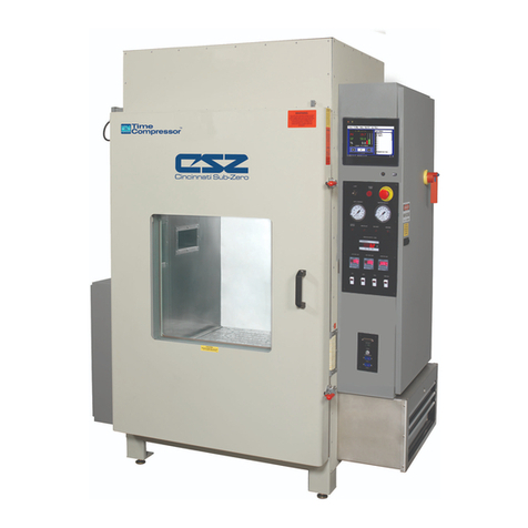
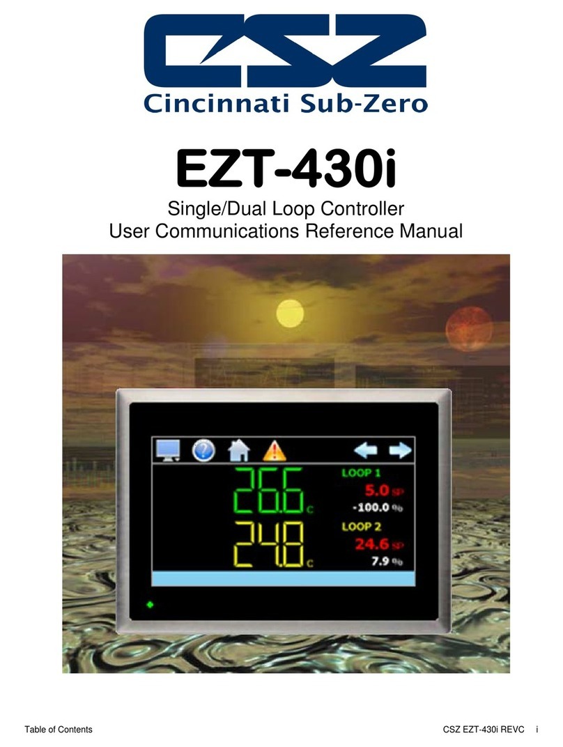
CSZ EZT-570i User manual

EZT570i User Communication Reference Manual revA
EZT-570i
User Communication Reference Manual

EZT-570i User Communication Reference Manual
2
TABLE OF CONTENTS
1. Introduction....................................................................................................... 3
1.1 Definition of Terms................................................................................................................ 3
2. Serial Communication...................................................................................... 5
2.1 Interface Standards .............................................................................................................. 6
2.1.1 Interface Converters ................................................................................................ 7
2.2 Protocol................................................................................................................................. 8
2.3 Write your own Modbus Application ................................................................................... 10
2.3.1 Packet Syntax........................................................................................................ 12
2.4 EZT-570i Control Registers ................................................................................................ 15
2.5 EZT-570i Profile Registers ................................................................................................. 35
2.5.1 Profile Download Algorithm ................................................................................... 41
2.5.2 Sending a Profile to the EZT-570i ......................................................................... 43
2.5.3 Starting a Profile in the EZT-570i .......................................................................... 44
Appendix
Common Terms and Definitions

EZT-570i User Communication Reference Manual
3
1. Introduction
This document is targeted towards new users interested in using data communications with CSZ
EZT-570i controllers. The purpose of this manual is to enable users to:
1. Understand the basics of data communications via standard definitions, interfaces and
protocols.
2. Set up and use a simple network of one or more EZT-570i controller(s).
In this manual, numbers in the format 0x00 represent values in hexadecimal. Numbers in the format
0 represent values in decimal and finally, numbers in the format 00000000 represent values in
binary unless otherwise stated.
1.1 Definition of Terms
Machine-to-Machine Communication
In order for machines to communicate with each other, they need a code called a character format or
character set. They need rules called protocol to govern their conversation and prevent confusion and
errors. Computers need a connecting interface over which to communicate. They may use one pair
of wires to send information in one direction and another pair to send in the opposite direction (full
duplex). Or they may use one pair to send in both directions (half duplex).
Character Format
The code or character format for the EZT-570i data communication is shared by virtually everyone in
the electronics industry. This code defines a computer stream of 1’s and 0’s, that are created by
varying a voltage signal in a regular manner. This code is the American Standard Code for
Information Interchange, called ASCII.
Bits and Bytes
The word bit is simply the contraction of the words binary digit. A bit is the basic unit in ASCII. It is
either a “1” or a “0”. A byte is a string of eight bits that a computer treats as a single character. ASCII
can use a single byte to represent each letter of the alphabet, each digit and each punctuation mark
we use.
ASCII
The ASCII code defines 128 separate characters, one for each letter, digit and punctuation mark.
ASCII also includes control characters similar to those we find on computer keys, such as backspace,
shift and return. It also has nine communications control characters for identification, enquiry
(inquiry), start of text, end of text, end of transmission, acknowledge, negative acknowledge and
escape. The ASCII code is sometimes written in a base 16 number system that is called
hexadecimal or “hex” for short. The numbers 0 through 9 represents the first ten digits of this system,
and the letters A through F represents the final six digits. The 128 ASCII character codes with the
decimal, binary and hexadecimal equivalents are listed in the following table.
ASCII Control Codes
ASCII Control Codes are used to give instructions to the remote device and result in specific actions,
such as a line feed instruction on a printer. ASCII Control Codes, the first 33 ASCII characters (non
printable), are important for the operation of communicating equipment. They give instruction to
remote devices that result in specific actions such as a line feed on a printer. Holding down the
keyboard control key while pressing the appropriate keyboard key is what sends these values.

EZT-570i User Communication Reference Manual
4
ASCII Character Chart
Char Code Decimal Binary Hex Char Code Decimal Binary Hex
NUL Ctrl @ 0 00000000 00 @Shift 2 64 01000000 40
SOH Ctrl A 1 00000001 01
A
Shift A 65 01000001 41
STX Ctrl B 2 00000010 02 BShift B 66 01000010 42
ETX Ctrl C 3 00000011 03 CShift C 67 01000011 43
EOT Ctrl D 4 00000100 04 DShift D 68 01000100 44
ENQ Ctrl E 5 00000101 05 EShift E 69 01000101 45
ACK Ctrl F 6 00000110 06 FShift F 70 01000110 46
BEL Ctrl G 7 00000111 07 GShift G 71 01000111 47
BS Ctrl H 8 00001000 08 HShift H 72 01001000 48
TAB Ctrl I 9 00001001 09 IShift I 73 01001001 49
LF Ctrl J 10 00001010 0A JShift J 74 01001010 4A
V
T Ctrl K 11 00001011 0B
K
Shift K 75 01001011 4B
FF Ctrl L 12 00001100 0C LShift L 76 01001100 4C
CR Ctrl M 13 00001101 0D MShift M 77 01001101 4D
SO Ctrl N 14 00001110 0E NShift N 78 01001110 4E
SI Ctrl O 15 00001111 0F OShift O 79 01001111 4F
DLE Ctrl P 16 00010000 10 PShift P 80 01010000 50
DC1 Ctrl Q 17 00010001 11 QShift Q 81 01010001 51
DC2 Ctrl R 18 00010010 12 RShift R 82 01010010 52
DC3 Ctrl S 19 00010011 13 SShift S 83 01010011 53
DC4 Ctrl T 20 00010100 14 TShift T 84 01010100 54
NAK Ctrl U 21 00010101 15 UShift U 85 01010101 55
SYN Ctrl V 22 00010110 16
V
Shift V 86 01010110 56
ETB Ctrl W 23 00010111 17 WShift W 87 01010111 57
CAN Ctrl X 24 00011000 18
X
Shift X 88 01011000 58
EM Ctrl Y 25 00011001 19
Y
Shift Y 89 01011001 59
SUB Ctrl Z 26 00011010 1A ZShift Z 90 01011010 5A
ESC Ctrl [ 27 00011011 1B [[ 91 01011011 5B
FS Ctrl \ 28 00011100 1C
\
\ 92 01011100 5C
GS Ctrl ] 29 00011101 1D ]] 93 01011101 5D
RS Ctrl ^ 30 00011110 1E ^Shift 6 94 01011110 5E
US Ctrl _ 31 00011111 1F _Shift - 95 01011111 5F
SP SPACE 32 00100000 20 `` 96 01100000 60
! Shift 1 33 00100001 21 aA 97 01100001 61
" Shift ‘ 34 00100010 22 bB 98 01100010 62
# Shift 3 35 00100011 23 cC 99 01100011 63
$ Shift 4 36 00100100 24 dD 100 01100100 64
% Shift 5 37 00100101 25 eE 101 01100101 65
& Shift 7 38 00100110 26
f
F 102 01100110 66
‘ ‘ 39 00100111 27 gG 103 01100111 67
( Shift 9 40 00101000 28 hH 104 01101000 68
) Shift 0 41 00101001 29 II 105 01101001 69
* Shift 8 42 00101010 2A jJ 106 01101010 6A
+ Shift = 43 00101011 2B kK 107 01101011 6B
, , 44 00101100 2C
lL 108 01101100 6C
- - 45 00101101 2D
mM 109 01101101 6D
. . 46 00101110 2E
nN 110 01101110 6E
/
/ 47 00101111 2F
oO 111 01101111 6F
0 0 48 00110000 30 pP 112 01110000 70
1 1 49 00110001 31 qQ 113 01110001 71
2 2 50 00110010 32 rR 114 01110010 72
3 3 51 00110011 33 sS 115 01110011 73
4 4 52 00110100 34 tT 116 01110100 74
5 5 53 00110101 35 uU 117 01110101 75
6 6 54 00110110 36 vV 118 01110110 76
7 7 55 00110111 37 wW 119 01110111 77
8 8 56 00111000 38 xX 120 01111000 78
9 9 57 00111001 39 yY 121 01111001 79
: Shift ; 58 00111010 3A zZ 122 01111010 7A
; ; 59 00111011 3B
{Shift [ 123 01111011 7B
< Shift , 60 00111100 3C |Shift \ 124 01111100 7C
= = 61 00111101 3D
}Shift ] 125 01111101 7D
> Shift . 62 00111110 3E ~Shift ` 126 01111110 7E
? Shift / 63 00111111 3F DEL Delete 127 01111111 7F

EZT-570i User Communication Reference Manual
5
2. Serial Communication
The primary interface CSZ has chosen for the EZT-570i employs serial communication, which is the
exchange of data in a one-bit-at-a-time, sequential manner on a single data line or channel. Serial
contrasts with parallel communication, which sends several bits of information simultaneously over
multiple lines or channels. Not only is serial data communication simpler than parallel, it is also less
costly.
Baud Rate
The baud unit is named after Jean Maurice Emile Baudot, who was an officer in the French Telegraph
Service. He is credited with devising the first uniform-length 5-bit code for characters of the alphabet
in the late 19th century. What baud really refers to is modulation rate or the number of times per
second that a line changes state. This is not always the same as bits per second (BPS). However, if
you connect two serial devices together using direct cables then baud and BPS are in fact the same.
Thus, if you are running at 9600 BPS, then the line is also changing states 9600 times per second.
Typical baud rates for computers are 9600, 19200, 38400 and 57600 baud. As the baud rate
increases, so does the transmission rate of data. Thus you get more information in a shorter period
of time. However, the faster the transmission rate, the more susceptible it is to error due to the
quality of the cable and sources of electrical “noise” in the environment. In order to balance
throughput with reliability, CSZ has chosen to use 9600 baud as the data rate for the EZT-570i. Thus
a device used to communicate with the EZT-570i must have its serial port set for 9600 baud in order
to for data communications to work properly.
Start and Stop Bits
The start bit informs the receiving device that a character is coming, and a stop bit tells it that a
character is complete. The start bit is always a 0. The stop bit is always a 1. The human speech
equivalent of these bits could be a clearing of the throat to get someone’s attention (start bit); and a
pause at the end of a phrase (stop bit). Both help the listener understand the message.
A stop bit has a value of 1 - or a mark state - and it can be detected correctly even if the previous
data bit also had a value of 1. This is accomplished by the stop bit's duration. Stop bits can be 1,
1.5, or 2 bit periods in length. CSZ has chosen to use the default – and most common – length of 1
period for the EZT-570i. A device used to communicate with the EZT-570i must also have its serial
port set to use a stop bit of 1 in order for data communications to work properly.
Parity Bit
Besides the synchronization provided by the use of start and stop bits, an additional bit called a parity
bit may optionally be transmitted along with the data. A parity bit affords a small amount of error
checking, to help detect data corruption that might occur during transmission. You can choose either
even parity, odd parity, mark parity, space parity or none at all. When even or odd parity is being
used, the number of marks (logical 1 bits) in each data byte are counted, and a single bit is
transmitted following the data bits to indicate whether the number of 1 bits just sent is even or odd.
For example, when even parity is chosen, the parity bit is transmitted with a value of 0 if the number
of preceding marks is an even number. For the binary value of 0110 0011 the parity bit would be 0.
If even parity were in effect and the binary number 1101 0110 were sent, then the parity bit would be
1. Odd parity is just the opposite, and the parity bit is 0 when the number of mark bits in the
preceding word is an odd number. Mark parity means that the parity bit is always set to the mark
signal condition and likewise space parity always sends the parity bit in the space signal condition.
Since these two parity options serve no useful purpose whatsoever, they are almost never used. The
EZT-570i can be set for even, odd or no parity. A device used to communicate with the EZT-570i
must also have its serial port set to use the same parity setting as the EZT-570i in order for data
communications to work properly.

EZT-570i User Communication Reference Manual
6
2.1 Interface Standards
An interface is a means for electronic systems to interact. It’s a specific kind of electrical wiring
configuration. CSZ has selected to use two of the most common serial interfaces used today. This
provides both a simple 1 to 1 connection to a PC or PLC using readily available cabling as well as a
multi-drop connection where more than one EZT-570i can be placed on the line.
EIA-232 (Full Duplex)
An EIA-232 (formerly RS-232C) interface uses three wires: a single transmit wire; a single receive
wire; and a common line. Only two devices can use an EIA-232 interface. A -3 to -24 volt signal
indicates a 1 and a +3 to +24 volt signal indicates a 0. The EIA-232 signal is referenced to the
common line rather than to a separate wire, as in EIA-485. Thus, an EIA-232 cable is limited to a
maximum of 50 feet, due to noise susceptibility.
EIA-485 (Half Duplex)
An EIA-485 interface uses two wires: a T+/R+, a T-/R- line. A -5-volt signal is interpreted as a 1, a
+5-volt signal as a 0. As many as 31 remote devices can be connected to a master on a multi-drop
network up to 4000 feet long.
Wiring
Most PCs have a standard EIA-232 port (usually referred to as RS-232). In these instances, you
must use an interface converter to connect to EIA-485. These interface standards are required to
have a multi-drop system (more than one EZT-570i on the link). The following list references some
vendors who sell these converters. Should your PC have the appropriate interface, just connect
using the wiring shown in the Getting Started section.
For EIA-485, the terminal marked “A” usually connects to the T+/R+ while the “B” terminal connects to
the T-/R- of the EZT-570i controller. The standards do not specify the wire size and type. Use of
AWG 24 twisted pair provides excellent results. If shielded cable is used, terminate the shield at one
end only. Always follow the manufacturer’s instructions supplied with the interface converter. See
Biasing of Buses next.
Biasing of Buses
The EIA-485 standard requires the bus to be biased for reliable communication. This requires
termination resistors to be placed across the T+/R+ and T-/R- wires. One resistor is placed at the PC
where it connects to the EIA-485 bus. The second resistor is placed at the last controller on the
network. Do not place resistors at each controller. The impedance of the wires used for the bus
determines the resistor value. For twisted pair, the value is typically 120 ohms. In addition, it may be
necessary to have a pull-up and pull-down resistor between the power supply and ground of the
interface adapter.
Check the documentation that came with your interface adapter. Biasing the bus reduces reflection
of signals sent down the bus. These reflections are sometimes referred to as a standing wave. This
condition is most notable when communicating at high baud rates over longer distances.

EZT-570i User Communication Reference Manual
7
2.1.1 Interface Converters
The purpose of an interface converter is to allow two different buses to be connected together.
Interface converters are required when connecting an EIA-232 port to an EIA-485 bus. The EIA-485
bus is a half duplex bus. This means that it can only send or receive data at any given time. Some
interface converters on the market provide the ability to have full duplex with the EIA-485 bus. This is
accomplished by using two receivers and transmitters tied in tandem. This type of converter will not
work with the EZT-570i controller. Be sure that the model you purchase is designed for half duplex.
Another consideration when selecting an interface converter is how the converter handles switching
between transmit and receive. Typically it is accomplished via a handshake line from the PC. When
data flows into the converter from the PC, a handshake line is placed high. When data flows out of
the converter to the PC, the handshake line is placed low. In this way, the handshake line controls
the direction of information. Another method of achieving this is to use a built-in timer. The converter
switches to transmit when a character is sent to it from the PC. After a period of time when the PC
has not transmitted, the converter switches to a receive mode.
It is important that you understand how your converter accomplishes this task. You are required to
wire this feature or make settings on the converter to enable this function. The PC will not talk to the
controller correctly with out properly setting this. Your converter may also require settings through dip
switches, to set up communications parameters like baud rate, data bits, start bits, stop bits and
handshaking. The converter may also require a separate power supply. Some converters get their
power from the handshake lines of the PC. If you rely on this method, you will need to wire these
additional lines. In addition, your software must set these lines high. A more reliable method is to
use the external power supply. This is especially necessary when using a laptop computer. See the
documentation that is provided with your converter for more detail.
Not all converters are equal in performance. If your chamber operates in a harsh, electrically noisy
environment, this can cause less robust converters to work intermittently or not at all. CSZ has only
tested the converters listed below; however, CSZ makes no claims as to the performance or
compatibility of these converters with your PC. These converters are equipped with automatic send
data control circuits, driver control in the converter hardware, so you don’t have to work with software
at all. The circuit monitors data flow and enables the driver during transmission and automatically
disables it when no data is being sent. There is no need to rework software or install new drivers.
B&B Electronics
707 Dayton Road
PO Box 1040
Ottawa, IL 61350
Phone 815-433-5100
http://www.bb-elec.com
Part # 485OI9TB for EIA-232 to EIA-85
Part # 485PS2 (external power supply – required if handshake lines unavailable for power)
RESmith
4311 Smith Drive
Hamilton, OH 45011
Phone 513-874-4796
http://www.RS485.com
Part # ASC24T-B9FPS for EIA-232 to EIA-485 (provided with adapter cables and power supply)

EZT-570i User Communication Reference Manual
8
2.2 Protocol
Protocol describes how to initiate an exchange. It also prevents two machines from attempting to
send data at the same time. There are a number of different data communications protocols, just as
there are different human cultural protocols that vary according to the situation.
The protocol portion of EZT-570i communications is very important, because it provides a quality of
communication that others often don’t have. Protocol-driven communications are more accurate,
because they are less prone to both operator and noise errors. Protocol maintains system integrity
by requiring a response to each message. It’s like registered mail — you know that your letter has
been received because the post office sends you a signed receipt.
In EZT-570i data communications, a dialog will continue successfully as long as the messages are in
the correct form and responses are returned to the protocol leader. If the operator enters an incorrect
message, or interference comes on to the data line, there will be no response. In that case the
master must retransmit the message or go to a recovery procedure. If an operator continues to enter
an incorrect message or interference continues on the data line, the system will halt until the problem
is resolved. CSZ has selected Modbus RTU as the protocol of choice. Modbus RTU enables a PC to
read and write directly to registers containing the EZT-570i’s parameters. With it, you can read all
180 of the controller’s parameters with three read commands.
Modbus Remote Terminal Unit (RTU)
Gould Modicon, now called AEG Schneider, created this protocol for process control systems called
"Modbus". It has the advantage over other protocols of being extremely reliable in exchanging
information. This protocol works on the principle of packet exchanges. The packet contains the
address of the controller to receive the information, a command field that says what is to be done with
the information and several fields of data. Reading from these registers retrieves all information in
the controller. The last item sent in the packet is a field to ensure the data is received intact. This is
called a cyclic redundancy check-sum. See the following example for information on how to generate
this value. All information exchanged is in hex numbers. The EZT-570i only supports the binary
version of Modbus, referenced as RTU. The ASCII version is less efficient and is not supported.
The CRC (Cyclical Redundancy Checksum) is calculated by the following steps:
1. Load a 16-bit register (called CRC register) with 0xFFFF
2. Exclusive OR the first 8-bit byte of the command message with the low order byte of the 16-bit
CRC register, putting the result in the CRC register.
3. Shift the CRC register one bit to the right with MSB zero filling. Extract and examine the LSB.
4. If the LSB of the CRC register is zero, repeat step 3, else Exclusive OR the CRC register with the
polynomial value 0xA001.
5. Repeat steps 3 and 4 until eight shifts have been performed. When this is done, a complete 8-bit
byte will have been processed.
6. Repeat steps 2 through 5 for the next 8-bit byte of the command message. Continue doing this
until all bytes of the command message have been processed. The final contents of the CRC
register is the CRC value.
When transmitting the CRC value in the message, the upper and lower bytes of the CRC value
must be swapped, i.e. the lower order byte will be transmitted first.

EZT-570i User Communication Reference Manual
9
Cyclical Redundancy Checksum (CRC) Algorithm
unsigned int calc_crc(unsigned char *start_of_packet, unsigned char *end_of_packet)
{
unsigned int crc;
unsigned char bit_count;
unsigned char *char_ptr;
/* Start at the beginning of the packet */
char_ptr = start_of_packet;
/* Initialize CRC */
crc = 0xFFFF;
/* Loop through the entire packet */
do{
/* Exclusive-OR the byte with the CRC */
crc ^= (unsigned int)*char_ptr;
/* Loop through all 8 data bits */
bit_count = 0;
do{
/* If the LSB is 1, shift the CRC and XOR the polynomial mask with the CRC */
if(crc & 0x0001){
crc >>= 1;
crc ^= 0xA001;
}
/* If the LSB is 0, shift the CRC only */
else{
crc >>= 1;
}
} while(bit_count++ < 7);
} while(char_ptr++ < end_of_packet);
return(crc);
}

EZT-570i User Communication Reference Manual
10
2.3 Write your own Modbus Application
Listed below are a few of the more common software packages that claim to support the Modbus
protocol. CSZ does not recommend any one software package nor supports the implementation of
any software package not sold by CSZ. This list is provided as informational only. CSZ makes no
claims as to the performance or compatibility of any software package with your. Contact the
software manufacturer for more information on applying their software.
LabView by National Instruments
6504 Bridge Point Parkway
Austin, TX 78730-5039
Phone 512-794-0100
http://www.natinst.com
OI-2000 by Software Horizons, Inc.
10 Tower Office Park
Suite 200
Woburn, MA 01801-2120
Phone 617-933-3747
http://www.shorizons.com
SpecView by SpecView, LLC
41 Canyon Green Court
San Ramon, CA 94583
Phone 510-275-0600
http://www.specview.com
Wonderware 2000 by Wonderware
Corp.
100 Technology Drive
Irvine, CA 92718
Phone 714-727-3200
http://www.wonderware.com

EZT-570i User Communication Reference Manual
11
If you already have a software application that uses Modbus, you can simply skip to EZT-570i
parameter table in the Getting Started section for the information your program requires. The rest of
this section provides information on writing a software application that uses Modbus.
1. You need to code messages in eight-bit bytes, with event parity, one stop bit (8, even, 1). The
EZT-570i has its parity set to even as default from the factory. If a different parity setting is
desired, just set the EZT-570i to match the coded parity setting.
2. Negative parameter values must be written in twos' complement format. Parameters are stored
in two-byte registers accessed with read and write commands to a relative address.
3. Messages are sent in packets that must be delimited by a pause at least as long as the time it
takes to send 28 bits (3.5 characters). To determine this time in seconds, divide 28 by the baud
rate. In the case of EZT-570i communications at 9600 baud, this calculates to a minimum period
of 3ms.
In addition, the EZT’s timeout period must be added to that, in order to properly time the send and
receive messages between the host computer and multiple EZT’s on the serial link. With a
default timeout period in the EZT-570i of 200ms, it makes a total pause of 203ms minimum.
4. Values containing decimal points such as process values and setpoints, have the decimal point
assumed, i.e., the data exchange can only be performed using whole numbers. Thus, the value
must be offset by a factor of 10 in order to exchange the data correctly. For example, a setpoint
of 42.4 degrees must be sent as a value of 424 in order for the EZT-570i to be set correctly.
Likewise, a process value read from the EZT-570i with a value of 967 is actually 96.7 degrees.
Consult the parameter table for the proper format of each value.
5. When monitoring a process, try to keep the number of read and write commands to a minimum of
500ms between exchanges to a single controller. Continuously reading data at a faster rate
consumes an excess amount of the controller’s processor time and does not provided any
additional benefits in process monitoring.
Handling Communication Errors
Reading or writing from/to a register that does not exist or is currently disabled will typically respond
with an erroneous value or result in a time-out response, i.e., the EZT will not respond with a return
message. Messages with the wrong format, timing or CRC are also ignored. A response will not be
given to them. Only messages with the proper format, timing and CRC will be acknowledged. It is
the user’s responsibility to handle the error appropriately within their own software and determine
whether to resend the message or halt for operator intervention.
User Responsibility
Refrain from altering prompts that do not appear on the EZT-570i’s front panel or are not included on
the specific model. Care must also be taken that the process can not cause damage to property or
injury to personnel if the wrong commands are sent due to operator error or equipment malfunction.
Be sure to use limit devices on any equipment placed inside the chamber that can generate heat to
prevent system thermal runaway.

EZT-570i User Communication Reference Manual
12
2.3.1 Packet Syntax
Each message packet begins with a one-byte controller address, from 0x01 to 0xF7. The second
byte in the message packet identifies the message command: read (0x03); write (0x10); or loop back
(0x08). The next n bytes of the message packet contain register addresses and/or data. The last two
bytes in the message packet contain a two-byte Cyclical Redundancy Checksum (CRC) for error
detection.
Packet format:
address
command
registers and/or data
CRC
Read Register(s) Command (0x03)
This command returns from 1 to 60 registers. This command is to be used for reading one or more
data locations from the EZT-570i.
Packet sent to EZT-570i:
controller address (1 byte)
read command (0x03)
starting register high byte
starting register low byte
number of registers high byte (0x00)
number of registers low byte
CRC low byte
CRC high byte
Packet returned from EZT-570i:
controller address (1 byte)
read command (0x03)
number of bytes (1 byte)
first register data low byte
first register data high byte
…
…
register n data high byte
register n data low byte
CRC low byte
CRC high byte
Example: Read register 61 (chamber temperature) of controller at address 1.
Sent: 01 03 00 3D 00 01 15 C6
Received: 01 03 02 00 EC B9 C9
Message: 236 (0x00EC) – temperature is 23.6 degrees
nn nn nnnn… nn nn
nn 03 nn nn 00 nn nn nn
nn 03 nn nn nn … nn nn nn nn

EZT-570i User Communication Reference Manual
13
Example: Read registers 60 and 61 (chamber setpoint and temperature) of controller at address 1.
Sent: 01 03 00 3C 00 02 04 07
Received: 01 03 04 01 90 01 48 FA 44
Message: 400 (0x0190) and 328 (0x0148) – setpoint is 40.0 and temperature is 32.8 degrees
Write Register Command (0x06)
This command writes a value to a single register. This command is to be used for setting control
values in the EZT-570i. To set multiple values, repeat the command for each data location.
Packet sent to EZT-570i:
controller address (1 byte)
write command (0x06)
register high byte
register low byte
data high byte
data low byte
CRC low byte
CRC high byte
Packet returned from EZT-570i:
controller address (1 byte)
write command (0x06)
register high byte
register low byte
data high byte
data low byte
CRC low byte
CRC high byte
Example: Write register 60 (temperature set point) of controller at address one to 20 degrees.
Sent: 01 06 00 3C 00 C8 48 50
Received: 01 06 00 3C 00 C8 48 50
nn 06 nn nn nn nn nn nn

EZT-570i User Communication Reference Manual
14
Write Registers Command (0x10)
This command is for use with profile download only. It is used to transmit profile data one
step at a time to the EZT-570i. See the Profile Parameters section for the list of registers and
their use. If this command is used to write to registers other than the correct profile step
registers, the EZT-570i will respond with an acknowledge that the message was received;
however, the command will not be executed.
Packet sent to EZT-570i:
controller address (1 byte)
write command (0x10)
starting register high byte
starting register low byte
number of registers to write high byte (0x00)
number of registers to write low byte (0x0F)
number of data bytes (0x1E)
data high byte
data low byte
…
…
register n data high byte
register n data low byte
CRC low byte
CRC high byte
Packet returned from EZT-570i:
controller address (1 byte)
write command (0x10)
starting register high byte
starting register low byte
number of registers to write high byte (0x00)
number of registers to write low byte (0x0F)
CRC low byte
CRC high byte
nn 10 nn nn 00 0F 1E nn nn … nn nn nn nn
nn 10 nn nn 00 0F nn nn

EZT-570i User Communication Reference Manual
15
2.4 EZT-570i Control Registers
The EZT-570i is capable of utilizing up to five control loops and eight monitor inputs. The register list
in this section of the manual lists the associated values for all of the loops, inputs and their associated
alarms by the loop or monitor input number, i.e., 1 - 5 and 1 - 8. While the monitor inputs will be easy
to decipher, since they are shipped from the factory with the relative number in their tag name, the
loops are not. The loop names are defined by the chamber process they control, i.e., temperature,
humidity, etc., thus the number of control loops required and their function can vary between different
chamber models.
The EZT-570i displays all control loops and monitor inputs in sequential order. The loop/monitor
order can be viewed from the “All Loops View” screen. Starting at the top of the list and counting
down, the first entry is loop 1, the second is loop 2, and so on. The following chart provides a loop
number to controlled process reference for use in selecting the desired parameter from the register
list.
TEMPERATURE/HUMIDITY
MODELS ALTITUDE MODELS VTS/TSB
MODELS DTS MODELS
LOOP
1
TEMPERATURE
TEMPERATURE
TEMPERATURE
TEMPERATURE
HOT CHAMBER (BATH)
LEFT CHAMBER
2 PRODUCT HUMIDITY ALTITUDE HUMIDITY
COLD CHAMBER (BATH)
CENTER CHAMBER
3 - PRODUCT PRODUCT ALTITUDE PRODUCT
RIGHT CHAMBER
4 - - - PRODUCT
DUT LEFT BASKET
5 - - - -
DUT RIGHT BASKET
The chamber events also vary based on the model of chamber and options present. In order to turn
the chamber and associated options on and off, it is necessary to set the proper event. The chart
below provides the chamber event number and its associated function based on the chamber model.
The chamber events are listed in order from top to bottom on the EZT-570i “Manual Event Control”
screen.
STANDARD MODELS
(TMP/RH/ALTITUDE) VTS/TSB MODELS DTS MODELS
EVENT
1 CHAMBER HOT CHAMBER / BATH ON LEFT CHAMBER
2 HUMIDITY COLD CHAMBER (VTS ONLY) CENTER CHAMBER
3 AUX COOL AUX COOL AUX COOL
4 PURGE PURGE PURGE
5 ALTITUDE XFR HOT XFR LEFT
6 - XFR COLD XFR RIGHT
7 - XFR UNLOAD (TSB ONLY) RIGHT CHAMBER
8 - - -
9 INITIATE DEFROST INITIATE DEFROST (VTS ONLY) INITIATE DEFROST (CENTER ONLY)
10 PRODUCT CONTROL PRODUCT CONTROL PRODUCT CONTROL
11 REMOTE SETPOINT 1 REMOTE SETPOINT 1 REMOTE SETPOINT 1
12 REMOTE SETPOINT 2 REMOTE SETPOINT 2 REMOTE SETPOINT 2
13 REMOTE SETPOINT 3 REMOTE SETPOINT 3 REMOTE SETPOINT 3
14 REMOTE SETPOINT 4 REMOTE SETPOINT 4 REMOTE SETPOINT 4
15 REMOTE SETPOINT 5 REMOTE SETPOINT 5 REMOTE SETPOINT 5

EZT-570i User Communication Reference Manual
16
The control registers are grouped into three blocks of 60 (for a total of 180) registers relating to the
specific types of data they contain. The first group of 60 registers (0 – 59) contains the configuration
settings for various options on the EZT-570i as well as all of the alarm status, profile status and
manual on/off settings for the chamber. The second group of 60 registers (60 – 119) contains all of
the loop control/monitor settings which include the setpoint and alarm settings for each loop. The
third group of 60 registers (120 – 179) contains all of the optional monitor input settings including the
individual alarm settings for each.
Bit Oriented Parameters
Some of the values contained in the EZT-570i’s register base contain bit oriented values. This means
that each bit of the word indicates an on/off status for a specific setting or condition. In handling
these values, it is recommended that the word be converted to its binary equivalent.
By converting the value to its binary equivalent, it produces a Boolean array of true [bit on (1)] and
false [bit off (0)] values. This allows each bit to be examined individually. In the same manner,
creating a Boolean array of 16 bits produces an equivalent decimal value that can be sent to the EZT-
570i in order to set a control value.
For the purpose of this manual, parameters defined as bit oriented will have the function of each bit
associated with the bit’s index number in the data word. The index number is equal to that of a
typical array function. Thus, an index number of zero, selects the first bit in the word. An index
number of 1 selects the second bit in the word, and so on. This helps eliminate offset selection errors
that may occur when coding software and using array functions to select which bit in the word that is
required for examination.

EZT-570i User Communication Reference Manual
17
Adhere to the following list of registers and their allowable data ranges. Do not attempt to
write to any other register number than those listed below. Do not write to registers that are
for options your chamber does not have. Failure to adhere to this requirement can result in
erratic control and/or damage to equipment. Note that register numbers listed are relative
values. To convert to absolute values, add 40001.
0 (0x0000) EZT-570i Operational Mode
r 0 Offline (system maintenance mode)
1Online
When the EZT-570i is in maintenance mode, it no longer updates any of the
control register values. They remain at their previous setting until the EZT-570i is
placed back into normal operation. When offline, the chamber is not in operation.
1 (0x0001) Clock (YY/MM)
r 0-99 Year (high byte)
1-12 Month (low byte)
1January
2 February
3March
4April
5May
6June
7July
8 August
9 September
10October
11November
12December
This parameter contains both the current year and month of the EZT-570i’s clock.
The data contained in the word will be an integer value based on the combined
bytes of both the year and month. In order to obtain the individual values, split
the word into its two component bytes.
Example: 0x0801 read from EZT-570i
Splitting the word into its two component bytes yields 0x08 for the
high byte and 0x01 for the low byte. The high byte of 0x08 when
converted to decimal is 8 (year of 2008). The low byte of 0x01 when
converted to decimal is 1 (month of January).

EZT-570i User Communication Reference Manual
18
2 (0x0002) Clock (DAY/DOW)
r 1 - 31 Day of Month (high byte)
0 - 6 Day of Week (low byte)
0 Sunday
1 Monday
2Tuesday
3Wednesday
4Thursday
5Friday
6Saturday
This parameter contains both the current day of month and day of week of the
EZT-570i’s clock. The data contained in the word will be an integer value based
on the combined bytes of both the day of month and day of week. In order to
obtain the individual values, split the word into its two component bytes.
Example: 0x1702 read from EZT-570i
Splitting the word into its two component bytes yields 0x17 for the
high byte and 0x02 for the low byte. The high byte of 0x17 when
converted to decimal is 23 (23rd day of the month). The low byte of
0x02 when converted to decimal is 2 (Tuesday).
3 (0x0003) Clock (HH/MM)
r 1 - 23 Hours (high byte)
0 - 59 Minutes (low byte)
This parameter contains both the current hours and minutes of the EZT-570i’s
clock. The data contained in the word will be an integer value based on the
combined bytes of both the hours and minutes. In order to obtain the individual
values, split the word into its two component bytes.
Example: 0x1131 read from EZT-570i
Splitting the word into its two component bytes yields 0x11 for the
high byte and 0x31 for the low byte. The high byte of 0x11 when
converted to decimal is 17 (17:00 hours – 5pm). The low byte of
0x31 when converted to decimal is 49 (minutes). The resultant time
is 17:49 or 5:49pm.
4 (0x0004) Clock (seconds)
r 0-59seconds
5 (0x0005) Power Recovery Mode
r/w 0 Continue
1 Hold
2 Terminate
4 Reset
8 Resume
6 (0x0006) Power Out Time
r/w 0-32767seconds

EZT-570i User Communication Reference Manual
19
7 (0x0007) Defrost Operating Mode
r/w 0Disabled
1 Manual Mode Selected
2 Auto Mode Selected
8 (0x0008) Auto Defrost Temperature Setpoint
r/w -32768 – 32767 (-3276.8 – 3276.7 degrees)
This parameter contains an assumed decimal point. Since only whole numbers
can be sent to and received from the EZT-570i using Modbus protocol, the value
contained in this register must be divided by 10 to get the actual value. Likewise,
when sending a setpoint, the setpoint must be multiplied by 10 in order for it to be
set properly in the EZT-570i.
9 (0x0009) Auto Defrost Time Interval
r/w 0 - 32767 minutes
10 (0x000A) Defrost Status
r 0NotinDefrost
1 In Defrost
2 In Prechill
11 (0x000B) Time Remaining Until Next Defrost
r 0 - 32767 minutes
12 (0x000C) Product Control
r/w 0Off
1 Deviation
2 Process
4 Off
5 Deviation using Event for enable
6 Process using Event for enable
13 (0x000D) Product Control Upper Setpoint
14 (0x000E) Product Control Lower Setpoint
r/w -32768 – 32767 (-3276.8 – 3276.7 degrees)
These parameters contain an assumed decimal point. Since only whole
numbers can be sent to and received from the EZT-570i using Modbus protocol,
the values contained in these registers must be divided by 10 to get the actual
values. Likewise, when sending the setpoints, the setpoints must be multiplied
by 10 in order for it to be set properly in the EZT-570i.
15 (0x000F) Condensation Control
r/w 0Off
1 On
16 (0x0010) Condensation Control Monitor Mode
r/w 1 Use Single Input
2 Use Lowest Input
4 Use Highest Input
8 Use Average of all Inputs

EZT-570i User Communication Reference Manual
20
17 (0x0011) Condensation Control Input Selection
r/w Bit0 Product
Bit1 PV1 (monitor)
Bit2 PV2 (monitor)
Bit3 PV3 (monitor)
Bit4 PV4 (monitor)
Bit5 PV5 (monitor)
Bit6 PV6 (monitor)
Bit7 PV7 (monitor)
Bit8 PV8 (monitor)
This parameter is bit oriented, i.e., enabling the different bits of the word
enables (1) or disables (0) the use of the input for condensation control.
Note that if monitor inputs are not available on your chamber, the associated
bits should be set to zero.
Example: Select the product, PV1, PV5, PV6 and PV7 inputs for control
Set the bits of the word for the selected inputs. The bit number
defines the position (index) of the bit (element) in the word which
can be thought of as an array of bits starting at the LSB.
The bit values then become: 00000000 11100011. The decimal
equivalent of the binary array is 227 (0x00E3). By setting
register 17 to a value off 227, the selected inputs will be used.
18 (0x0012) Condensation Control Temperature Ramp Rate Limit
r/w 0 - 100 (0.0 – 10.0 degrees C)
0 - 180 (0.0 – 18.0 degrees F)
This parameter contains an assumed decimal point. Since only whole numbers
can be sent to and received from the EZT-570i using Modbus protocol, the value
contained in this register must be divided by 10 to get the actual value. Likewise,
when sending a setpoint, the setpoint must be multiplied by 10 in order for it to be
set properly in the EZT-570i.
19 (0x0013) Condensation Control Dewpoint Limit
20 (0x0014) Condensation Control Dewpoint Actual
r -32768 – 32767 (-3276.8 – 3276.7 degrees)
These parameters contain an assumed decimal point. Since only whole
numbers can be sent to and received from the EZT-570i using Modbus protocol,
the values contained in these registers must be divided by 10 to get the actual
values.
21 (0x0015) Chamber Light Control
r/w 0 Chamber Light Off
1 Chamber Light On
Other manuals for EZT-570i
2
Table of contents
Other CSZ Controllers manuals
Popular Controllers manuals by other brands

Basler
Basler SR6A instruction manual

Honeywell
Honeywell HVC0001 owner's guide

Huihao Electrical Products
Huihao Electrical Products HH378N instruction manual

EisSound
EisSound 092x3 Installation & user manual

IFM Electronic
IFM Electronic ecomot 300 AC1353 Supplementary device manual

Crestron
Crestron CN-TVAV Operation guide