CTEK 1046 User manual

EN
EN • 3
MANUAL
SAFETY
•Thechargerisdesignedforchargingonlybat-
teriesaccordingtothetechnicalspecication.
Donotusethechargerforanyotherpurpose.
Alwaysfollowbatterymanufacturers'userand
safetyrecommendations.
•Nevertrytochargenon-rechargeablebatteries.
•Neverplacethechargerontopofthebattery
orcoverthechargerwhencharging.
•Neverchargeafrozenordamagedbattery.
•NeverchargeaLi-batterywithtemperature
below0°C(32°F)ifnotspeciedbythebattery
manufacturer.
•Neveruseachargerwithdamagedcables.
Ensurethatthecableshavenotbeendamaged
byhotsurfaces,sharpedgesorinanyother
way.
•Neverplaceafan-cooledchargersothatdust,
dirtorsimilarcanbesuckedintothefan.
•Adamagedcablemustbereplacedbya
CTEKrepresentativeusinganoriginalpart
suppliedbyCTEK.Adetachablecablecanbe
replacedbytheuserusinganoriginalpartsup-
pliedbyCTEK.
•Connectiontothemainssupplymustbein
accordancewiththenationalregulationsfor
electricalinstallations.
•Chargerswithgroundedmainsplugmustonly
beconnectedtoagroundedsocketoutlet.
•Duringcharging,Lead-Acidbatteriescould
emitexplosivegases.Preventsparkscloseto
thebattery.Provideforgoodventilation.
•ChargerswithIP-classlowerthanIPx4are
designedforindooruse.Seetechnicalspeci-
cation.Donotexposetorainorsnow.
•Connectthechargertothebattery´spositive
poleandthentothenegativepole.Forbatter-
iesmountedinsideavehicle,connectthenega-
CONGRATULATIONS
tothepurchaseofyournewprofessionalswitchmodebatterycharger.Thischargeris
includedinaseriesofprofessionalchargersfromCTEKSWEDENABandrepresentsthe
latesttechnologyinbatterycharging.

4 • EN
tiveconnectiontothevehiclechassisremote
fromthefuelpipe.Thenconnectthechargerto
mainssupply.
•Disconnectthechargerfromthemainssupply.
Nextremovethenegativeconnection(vehicle
chassis)andthenthepositiveconnection.
•Don’tleaveanybatteryunattendedfora
longerperiodoftimeduringcharging.Ifany
erroroccursdisconnectthechargermanually.
•(IEC 7.12 ed.5)Thisapplianceisnot
intendedforusebypersons(includingchildren)
withreducedphysical,sensoryormentalcapa-
bilities,orlackofexperienceandknowledge,
unlesstheyhavebeengivensupervisionor
instructionconcerninguseoftheapplianceby
apersonresponsiblefortheirsafety.Children
shouldbesupervisedtoensurethattheydonot
playwiththeappliance.
(EN 7.12)Thisappliancecanbeusedby
childrenagedfrom8yearsandaboveand
personswithreducedphysical,sensoryor
mentalcapabilities,orlackofexperienceand
knowledgeiftheyhavebeengivensupervi-
sionorinstructionconcerninguseoftheappli-
anceinasafewayandunderstandthehazards
involved.Childrenshallnotplaywiththeappli-
ance.Cleaningandusermaintenanceshallnot
bemadebychildrenwithoutsupervision.

EN
EN • 5
NORMAL
BATTERY
PROGRAM
ERROR LAMP
AGM
BATTERY
PROGRAM
FULLY CHARGEDREADY TO USE
RECOND
PROGRAM SUPPLY
PROGRAM
POWER
LAMP
HOW TO CHARGE
1. Connectthechargertothebattery.
2.Connectthechargertothewallsocket.Thepowerlampwillindicatethatthemains
cableisconnectedtothewallsocket.Theerrorlampwillindicateifthebatteryclamps
areincorrectlyconnected.Thereversepolarityprotectionwillensurethatthebattery
orchargerwillnotbedamaged.
3.PresstheMODE-buttontoselectchargingprogram.
4.Followthe8-stepdisplaythroughthechargingprocess.
ThebatteryisreadytostarttheenginewhenSTEP4islit.
ThebatteryisfullychargedwhenSTEP7islit.
5.Stopchargingatanytimebydisconnectingthemainscablefromthewallsocket.
MODE-
BUTTON
TEMPERATURE
SENSOR
INDICATOR

6 • EN
CHARGING PROGRAMS
SettingsaremadebypressingtheMODE-button.Afterabouttwosecondsthecharger
activatestheselectedprogram.Theselectedprogramwillberestartednexttimethe
chargerisconnected.
The table explains the different Charging Programs:
Program Battery
Size (Ah) Explanation Temp range
20–300Ah Normal battery program
14.4V/10A.UseforWETbatteries,
Ca/Ca,MFandformostGELbatteries
-20°C–+50°C
(-4ºF–122ºF)
AGM 20–300Ah AGM battery program 14.7V/10A
UseforAGMbatteries. -20°C–+50°C
(-4ºF–122ºF)
RECOND 20–300Ah
Recond program 15.8V/1.5A
Usetoreturnenergytotheempty
WETandCa/Cabatteries.Recond
yourbatteryonceperyearandafter
deepdischaretomaximiselifetimeand
capacity.TheRecondprogramadds
STEP6tothenormalbatteryprogram.
-20°C–+50°C
(-4ºF–122ºF)
20–300Ah
Supply program 13.6V/10A
Useas12Vpowersupplyorusefor
floatmaintenancechargingwhen100%
capacityofthebatteryisrequired.
Supplyprogramactivatesstep7without
timeorvoltagelimitation.
-20°C–+50°C
(-4ºF–122ºF)
WARNING!
The spark protection on the battery charger
is disabled during SUPPLY program.
+
+
–
–
Comfort
Connect
CONNECT THE CHARGER TO A BATTERY
Comfort
Connect
Comfort
Connect
INFO
If the battery clamps are incorrectly
connected, the reverse polarity
protection will ensure that the battery
and charger are not damaged.
For batteries mounted inside a
vehicle
1. Connect the red clamp to the battery's
positive pole.
2. Connect the black clamp to the vehicle
chassis remote from the fuel pipe and
the battery.
3. Connect the charger to the wall socket.
4. Disconnect the charger from the wall
socket before disconnecting the battery.
5. Disconnect the black clamp before the
red clamp.

EN
EN • 7
BATTERY SIZE (Ah) TIME TO 80% CHARGED
20Ah 2h
50Ah 5h
100Ah 10h
200Ah 20h
READY TO USE
Thetableshowstheestimatedtimeforemptybatteryto80%charge
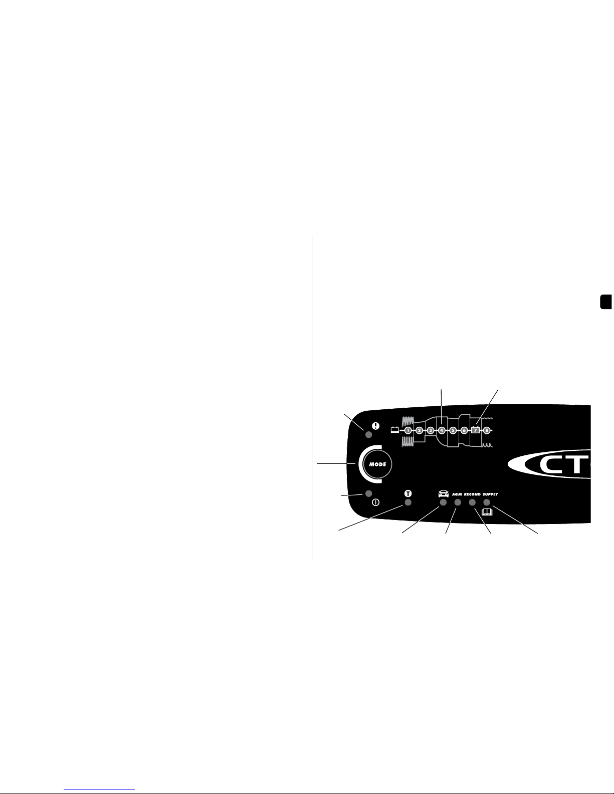
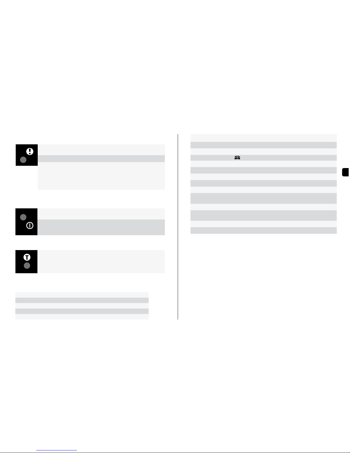
ERROR LAMP
Iftheerrorlampislit,checkthefollowing:
1. Is the chargers positive lead connected to the batterys
positive pole?
2. Is the charger connected to a 12V battery?
3. Has charging been interrupted in STEP 1, 2 or 5?
RestartthechargerbypressingtheMODE-button.Ifchargingisstill
beinginterrupted,thebattery...
STEP 1: ...is seriosly sulphated and may need to be replaced.
STEP 2: ...can not accept charge and may need to be replaced.
STEP 5: ...can not keep charge and may need to be replaced.
TEMPERATURE SENSOR
Thechargerisequippedwithatemperaturesensor.Thetemperaturesensor
willadjustthevoltagetotheambienttemperature.ForMXS10EC-the
temperaturesensorisnotdetachable.Activatedtemperaturesensorwillbe
indicatedbyalittemperaturesensorindicatorlamp.
POWER LAMP
Ifthepowerlampislitwitha:
1. STEADY LIGHT:
Themainscableisconnectedtothewallsocket.
2. FLASHING LIGHT:
Thechargerhasenteredtheenergysavemode.Thishappensifthe
chargerisn´tconnectedtothebatteryin2minutes.
TECHNICAL SPECIFICATIONS
Model number 1046
Rated Voltage AC 220–240VAC,50–60Hz
Charging voltage 14.4V,AGM14.7V,RECOND 15.8V,SUPPLY13.6V
Start voltage 2.0V
Charging current 10Amax
Current, mains 1.4Arms(atfullchargingcurrent)
Back current drain* Lessthan1Ah/month
Ripple** Lessthan4%
Ambient
temperature -20°Cto+50°C,outputpowerisreduced
automaticallyathightemperatures
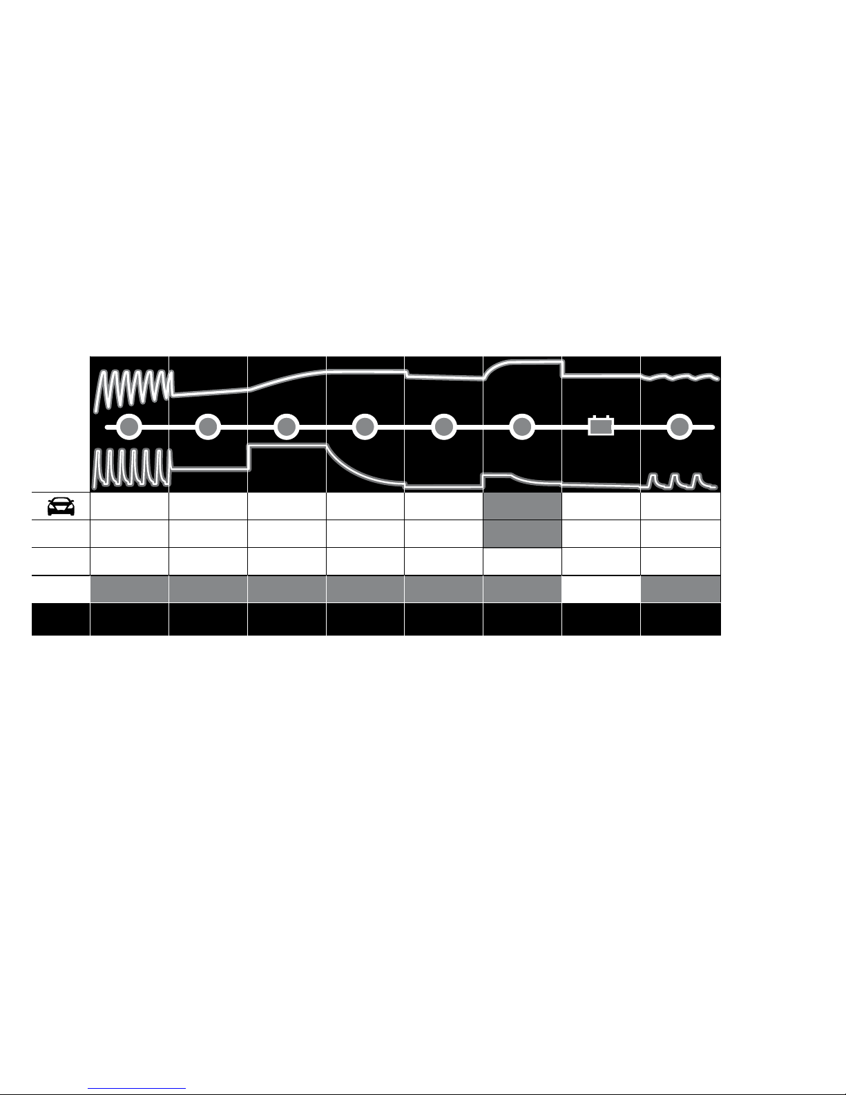
Charger type 8-step,fullyautomaticchargingcycle
Battery types Alltypesof12Vlead-acidbatteries
(WET,MF,Ca/Ca,AGMandGEL)
Battery capacity 20–300Ah
Insulation class IP65
*)Backcurrentdrainisthecurrentthatdrainsthebatteryifthechargerisnotconnected
tothemains.CTEKchargershasaverylowbackcurrent.
**)Thequalityofthechargingvoltageandchargingcurrentisveryimportant.Ahigh
currentrippleheatsupthebatterywhichhasanagingeffectonthepositiveelectrode.
Highvoltageripplecouldharmotherequipmentthatisconnectedtothebattery.CTEK
batterychargersproduceverycleanvoltageandcurrentwithlowripple.

8 • EN
STEP 1 DESULPHATION
Detectssulphatedbatteries.Pulsingcurrentandvoltage,removessulphatefromthelead
platesofthebatteryrestoringthebatterycapacity.
STEP 2 SOFT START
Testsifthebatterycanacceptcharge.Thissteppreventsthatchargingproceedswitha
defectbattery.
STEP 3 BULK
Chargingwithmaximumcurrentuntilapproximately80%batterycapacity.
STEP 4 ABSORPTION
Chargingwithdecliningcurrenttomaximizeupto100%batterycapacity.
STEP 5 ANALYSE
Testsifthebatterycanholdcharge.Batteriesthatcannotholdchargemayneedtobereplaced.
STEP 6 RECOND
Choose theRecondprogramtoaddtheRecondsteptothechargingprocess.DuringtheRecondstep
voltageincreasestocreatecontrolledgasinginthebattery.Gasingmixesthebatteryacidandgives
backenergytothebattery.
STEP 7 FLOAT
Maintainingthebatteryvoltageatmaximumlevelbyprovidingaconstantvoltagecharge.
STEP 8 PULSE
Maintainingthebatteryat95–100%capacity.Thechargermonitorsthebatteryvoltageandgivesa
pulsewhennecessarytokeepthebatteryfullycharged.
1
VOLTAGE (V)CURRENT (A)
ANALYSE RECOND PULSE
DESULPHATION SOFT START BULK ABSORPTION
15.8V
Increasing voltage
to 14.7V @ 25°C
10A
10A until 12.6V Increasing voltage
to 14.4V @ 25°C
10A
17
Limit: Max 20h Max 10h 3 minutes 30 min or 4h
depending on
battery voltage
10 days
Charge cycle restarts
if voltage drops*
Charge cycle restarts
if voltage drops
Max 8h
15.8V
15.8V 10A until 12.6V
10A until 12.6V
Increasing voltage
to 14.4V @ 25°C
10A
14.4V @ 25°C
Declining current
14.7V @ 25°C
Declining current
14.4V @ 25°C
Declining current
Checks if voltage
drops to 12V
Checks if voltage
drops to 12V
Checks if voltage
drops to 12V
Max 13.6V
10A
13.6V
10A
13.6V
10A
13.6V
10A
12.7V‒14.4V
10‒2A
12.7V‒14.7V
10‒2A
12.7V‒14.4V
10‒2A
Max 8h
2 3 4 5
FLOAT
6 8
RECOND
SUPPLY
AGM
Max 15.8V
1.5A
*Supply program is not time or voltage limited.
CHARGING PROGRAM

EN
EN • 9
LIMITED WARRANTY
CTEKSWEDENAB,issuesthislimitedwarrantytotheoriginalpurchaserofthisproduct.
Thislimitedwarrantyisnottransferable.Thewarrantyappliestomanufacturingfaults
andmaterialdefectsfor2yearsfromthedateofpurchase.Thecustomermustreturnthe
producttogetherwiththereceiptofpurchasetothepointofpurchase.Thiswarrantyisvoid
ifthebatterychargerhasbeenopened,handledcarelesslyorrepairedbyanyoneother
thanCTEKSWEDENABoritsauthorisedrepresentatives.Oneofthescrewholesinthe
bottomofthechargerissealed.Removingordamagingthesealwillvoidthewarranty.
CTEKSWEDENABmakesnowarrantyotherthanthislimitedwarrantyandisnotliable
foranyothercostsotherthanthosementionedabove,i.e.noconsequentialdamages.
Moreover,CTEKSWEDENABisnotobligatedtoanyotherwarrantyotherthanthis
warranty.
SUPPORT
Fore support and more information about CTEK products: www.ctek.com, info@ctek.com,
info@ctek.se,+46(0)22535180.Forlatestrevisedmanualseewww.ctek.com.

10 • EN
20014905G
Table of contents
Other CTEK Batteries Charger manuals

CTEK
CTEK XS 800 User manual

CTEK
CTEK D250S Dual User manual

CTEK
CTEK MULTI US 25000 User manual

CTEK
CTEK MULTI US 7000 User manual

CTEK
CTEK HOME LOAD BALANCING WITH CHARGESTORM CONNECTED... User manual

CTEK
CTEK ZAFIR 45 User manual

CTEK
CTEK MXS 5.0 Polar User manual

CTEK
CTEK MUS 4.3 TEST&CHARGE User manual

CTEK
CTEK E-MOBILITY CHARGESTORM Connected User manual

CTEK
CTEK MXS 10 User manual

CTEK
CTEK MXS 3.6 User manual

CTEK
CTEK MXS 5.0 CHECK User manual

CTEK
CTEK POWERSPORT User manual

CTEK
CTEK XS 0.8 User manual

CTEK
CTEK MUS 4.3 POLAR User manual

CTEK
CTEK MXTS 40 User manual

CTEK
CTEK MXS 3.6 User manual

CTEK
CTEK MXT 14000 AE User manual

CTEK
CTEK 1081 User manual

CTEK
CTEK MULTI XS 3600 Assembly instructions