3
Safety functions
mKomfy 1.8 has been developed for use in private homes. In order to
avoid too many false alarms, the cooker guard spends a short amount
of time analysing the information from the cooker hob. Cooker hobs
which are so powerful that they are able to start a fire in under 120
seconds work so quickly that the cooker guard may find it hard to
react before a fire is ignited, depending on the cookware and the
substances in it on the cooker hob.
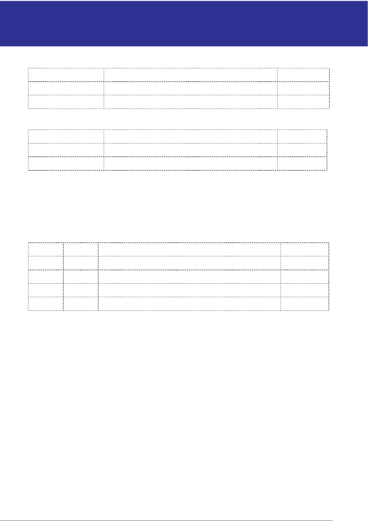
Overheating
The Cooker Guard monitors the temperature of the cooker and sounds the
alarm if it exceeds the upper limit.
The temperature alarm beeps 3 times every 5 seconds for 20 seconds and
a red light comes on in the sensor. Reduce the temperature of the cooker
immediately to prevent it being turned off, or press the control button on
the sensor to approve the higher temperature for aset time.
Anti-tamper function
The cooker guard has an integral safety function which detects if the
sensor is not correctly mounted in the fixing bracket. If the cooker is in
use and the sensor is incorrectly mounted, the security function will be
activated and beep 5 times in 5 seconds before turning the cooker off.
Replace the sensor in the wall bracket and press the control button to
continue using the cooker.
Optional timer function (see page 10 for activation)
When the Cooker Guard detects that the cooker has been turned on, itcan
start a built-in timer (countdown clock). When the timer reaches zero,
the cooker is turned off. The Cooker Guard will alert the user for the last 5
minutes. To restart the timer, press the control button on the sensor once.
To extend cooking time, hold the control button in for 10 seconds (see page
4).
NB: Where current measurement is used, the timer will start up when
power consumption is detected. If there is no power consumption for over
1 minute, the timer will revert to zero.
For example, when using the oven, the oven thermostat can disconnect
the power for over 1 minute, thus resetting the timer.
Use of current measurement (DIP 9)
When current measurement is used, the cooker guard safety function will
only be activated when power consumption by the cooker hob is detected.
The standard consumption here is approx. 280W. If the cooker consumes
less than 280W during use, the safety function will not be activated. This
limit can be tested and calibrated, see page 11.
2
Facts
The mKomfy Cooker Guard is a security product developed to
minimise the risk of fire when cooking.
mKomfy 1.8 sensor f.o.m. snr: 2024-000001 has a new fixing bracket (with lug)
which is not compatible with the previous version. The sensor works only with
Plug f.o.m. snr: 1840-000001.
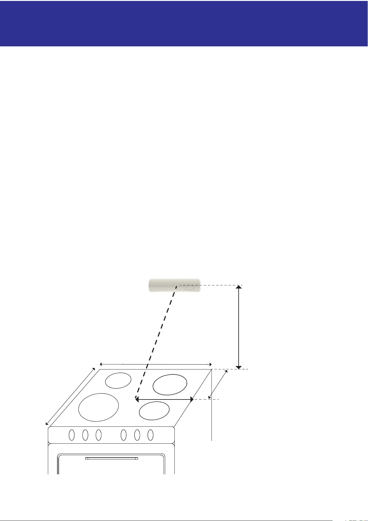
mKomfy 1.8 is a Class B cooker guard and does not react to flames
or smoke. It relies on a clear view from the sensor to the cooker
hob in order to detect heat. The cooker guard will thus be unable to
prevent a fire if the cooker hob is covered with flammable materials
(e.g. cardboard, newspaper), or if such materials catch fire near to the
cooker hob.
The product assumes normal care in the use of the cooker and
associated cookware. In normal use the cooker should be kept under
frequent observation, even if safety equipment such as mKomfy
is installed. Lots of smoke will be produced before the device is
triggered, so additional equipment such as Strømkutt could help to
make the kitchen a safer place.
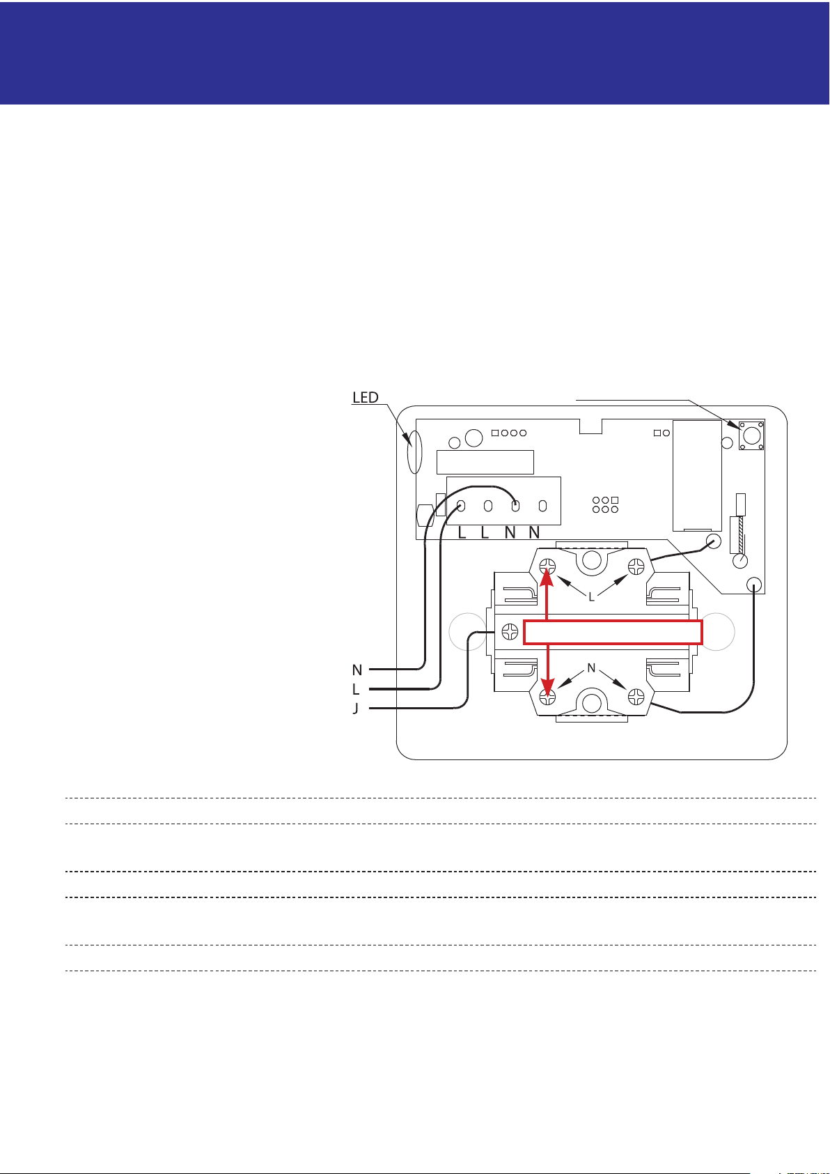
The product must be installed and maintained correctly as described,
and may only be fitted by an authorised electrician.
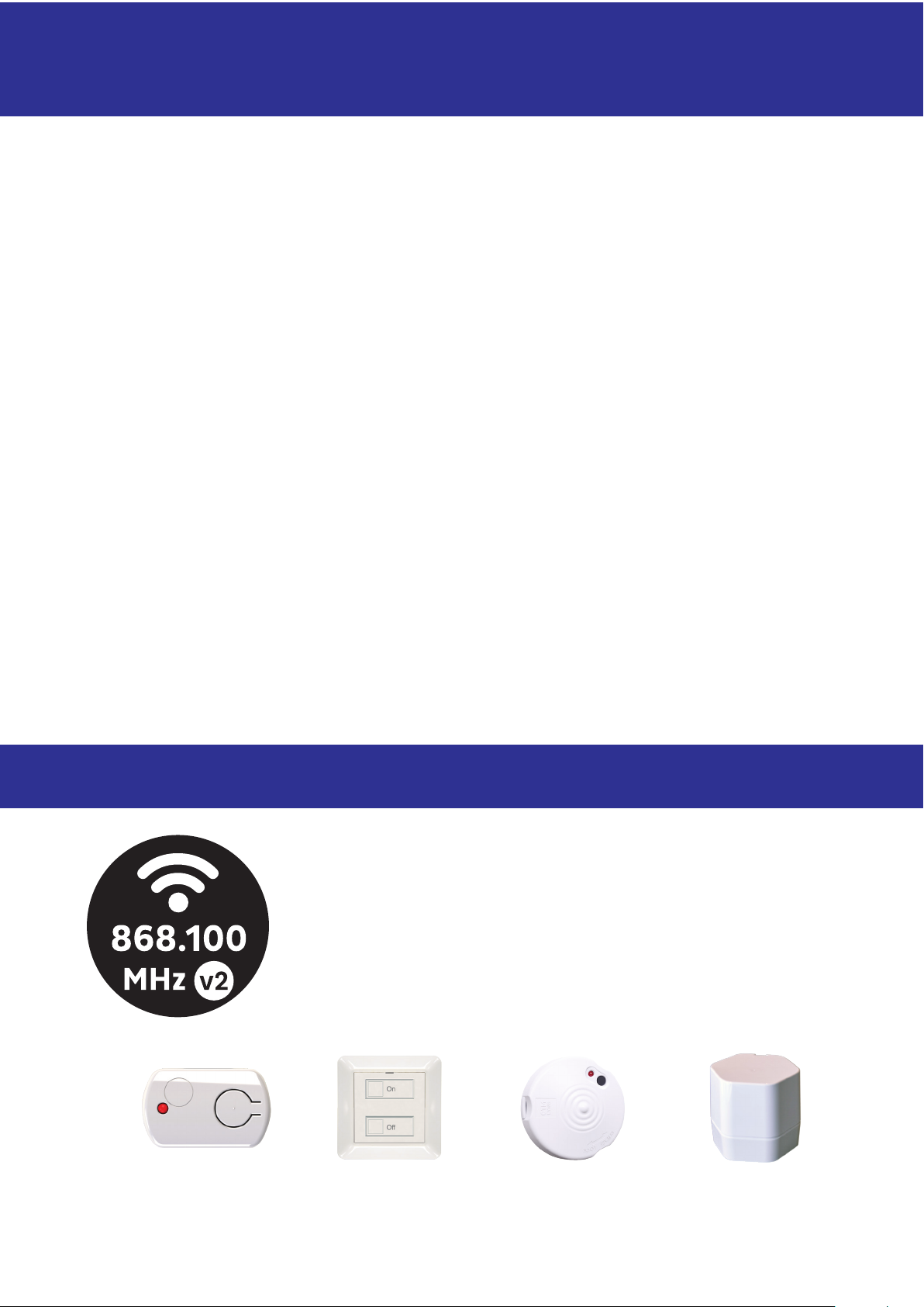
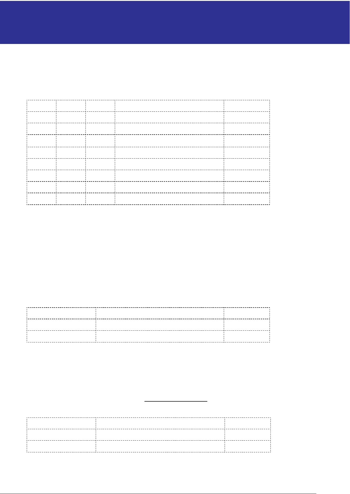
Accessories
Optional extras for the mKomfy 1.8 cover
additional needs and safety. Compatible with
newer wireless accessories labelled “v2”.
External
reset button
External
master switch
mTouch®
HUB
Smoke shut-off