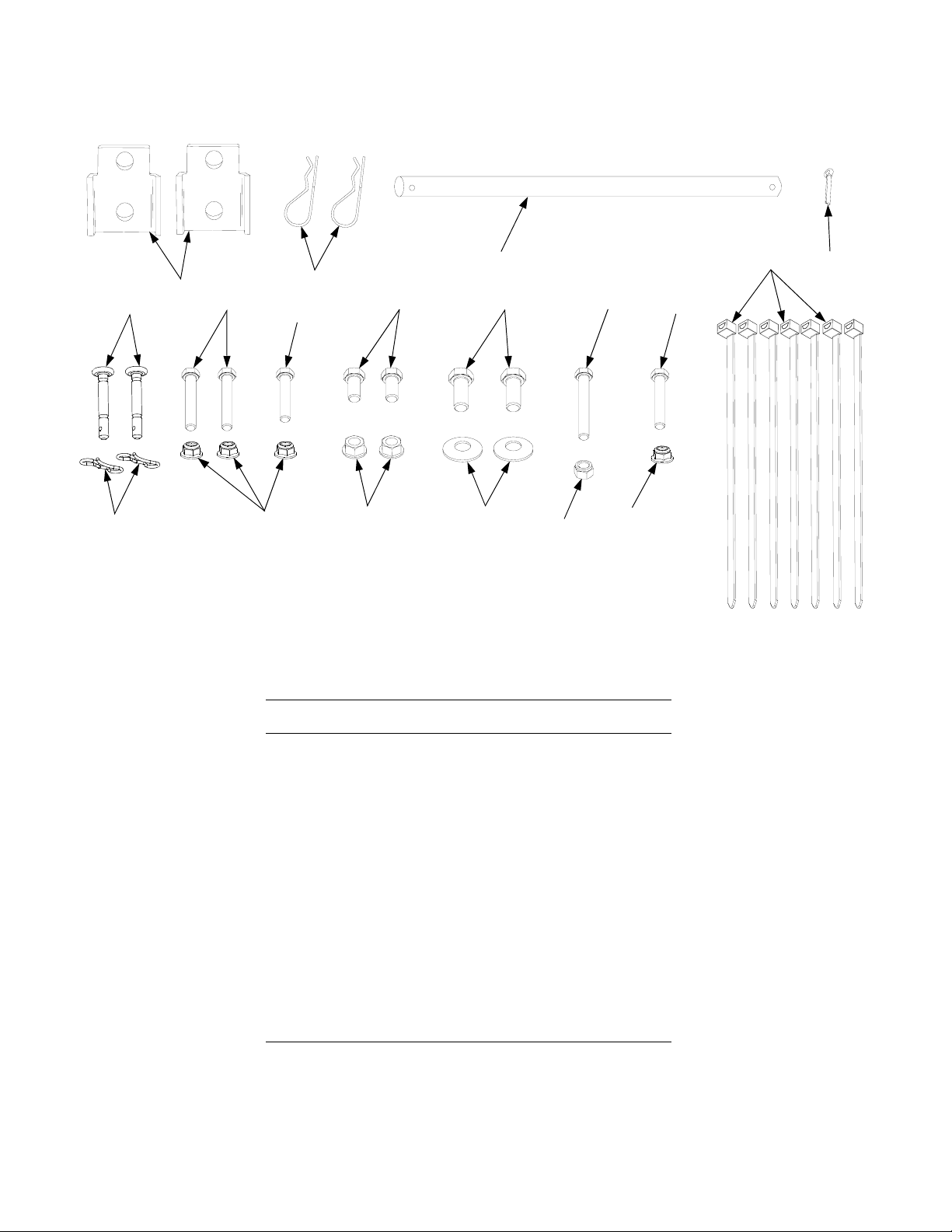
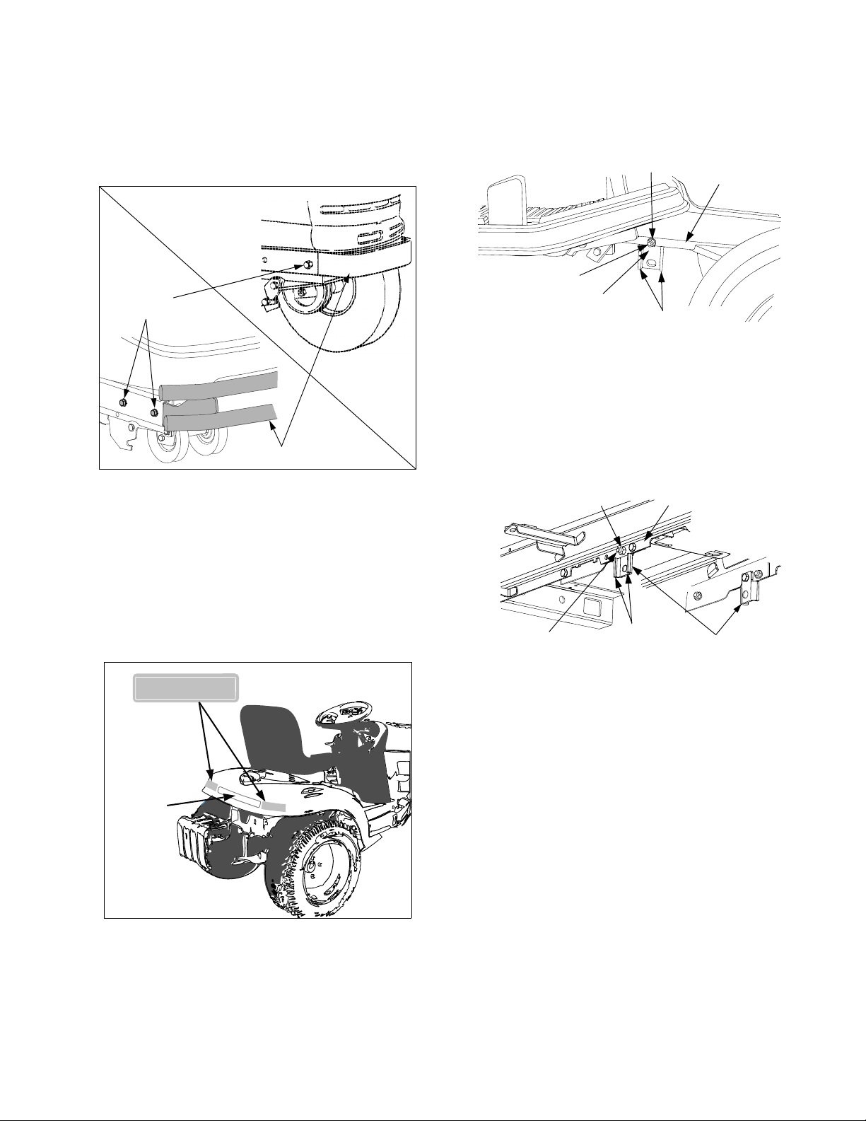
Cub Cadet 341 User manual

PRINTED IN U.S.A. FORM NO. 770-10430D
Model Number
341
(190-341-100)
IMPORTANT:
42" SNOW THROWER
READ SAFETY RULES AND INSTRUCTIONS CAREFULLY
INSTALLATION
Operator’s Manual
AND
For Cub Cadet
ATTACHMENT
MAINTENANCE INSTRUCTIONS
(7/07)
(Requires 190-307 Weight Bracket Kit and Weights)
CUB CADET LLC P.O. BOX 361131 CLEVELAND, OHIO 44136-0019 [www.cubcadet.com]
Series 2000/2500 Tractors

2
SAFE OPERATION PRACTICES FOR SNOW THROWERS
TRAINING
1. Read, understand, and follow all instructions on the
machine and in the manual before attempting to
assemble and operate. Keep this manual in a safe
place for future and regular reference.
2. Be familiar with all controls and their proper opera-
tion. Know how to stop the unit and disengage the
controls quickly.
3. Never allow children under 14 years old to operate
this machine. Children 14 years old and over should
read and understand the operation instructions and
safety rules in this manual and should be trained
and supervised by a parent. Never allow adults to
operate equipment without proper instructions.
4. No one should operate the unit while intoxicated or
while taking medication that impairs the senses or
reactions.
5. Thrown objects can cause serious personal injury.
Plan your snow-throwing pattern to avoid discharge
of material toward roads, bystanders and the like.
Stop the machine if anyone enters the area.
6. Keep bystanders,helpers, pets and children at least
75 feet from the machine while it is in operation.
Stop the machine if anyone enters the area.
7. Exercise caution to avoid slipping or falling when
mounting or dismounting the tractor.
PREPARATION
1. Thoroughly inspect the area where the equipment
is to be used. Remove all door mats, sleds, boards,
wires and other foreign objects which can be thrown
by the auger/impeller.
2. Disengage all clutches and shift into neutral before
starting the engine.
3. Do not operate equipment without wearing ade-
quate winter outer garments. Do not wear jewelry,
long scarfs or other loose clothing which could be-
come entangled in the moving parts of the machine.
Wear footwear which will improve footing on slip-
pery surfaces.
CONTENTS
Section Page
Safe Operation ........................................................................................................ 2
To The Owner ......................................................................................................... 5
I Introduction ............................................................................................................. 6
II Assembly ................................................................................................................ 8
III Installation and Removal ......................................................................................... 11
IV Adjustments and Operation .................................................................................... 14
V Maintenance ........................................................................................................... 18
VI Additional Accessory Requirements ....................................................................... 19
Warranty ................................................................................................................. 20
IMPORTANT
THIS SYMBOL POINTS OUT IMPORTANT SAFETY INSTRUCTIONS WHICH, IF NOT FOLLOWED,
COULD ENDANGER THE PERSONAL SAFETY AND/OR PROPERTY OF YOURSELF AND
OTHERS. READ AND FOLLOW ALL INSTRUCTIONS IN THIS MANUAL BEFORE ATTEMPTING
TO OPERATE YOUR UNIT. FAILURE TO COMPLY WITH THESE INSTRUCTIONS MAY RESULT
IN PERSONAL INJURY. WHEN YOU SEE THIS SYMBOL— HEED ITS WARNING.
SAFE OPERATION PRACTICES
WARNING
To reduce the potential for any injury, comply with the following safety instructions. Failure to comply with
the instructions may result in personal injury.

3
4. Check the fuel before starting the tractor engine.
Gasoline is an extremely flammable fuel. Always
use an approved fuel container to store gasoline.
Do not fill the fuel tank indoors while the engine is
running or while the engine is still hot. Replace the
gasoline cap securely and wipe off any spilled
gasoline before starting the engine. An ignition
spark or heat may ignite spilled fuel, causing a fire
or explosion.
5. Adjust the collector housing height to clear gravel or
crushed rock surfaces.
6. Never attempt to make any adjustments while the
engine is running (except where specifically
recommended by the manufacturer).
7. Let the engine and machine adjust to the outdoor
temperature before starting to clear snow.
8. Always wear safety glasses or eye shields during
operation, or while performing an adjustment or
repair, to protect your eyes. Thrown objects can
ricochet and cause serious injury to the eyes.
OPERATION
1. Do not put hands or feet near rotating parts, in the
auger housing or discharge chute. Contact with the
rotating parts can amputate hands and feet.
2. Exercise extreme caution when operating on, or
crossing, gravel drives, walks or roads. Stay alert
for hidden hazards or traffic. Do not carry
passengers.
3. After striking a foreign object, disengage the PTO,
stop the engine, remove the wire(s) from the spark
plug(s), and thoroughly inspect the snow thrower
for any damage. Repair the damage before
restarting and operating the snow thrower.
4. If the snow thrower should start to vibrate
abnormally, disengage the PTO, stop the engine
and check immediately for the causes. Vibration is
generally a warning sign of trouble.
5. Disengage the PTO and stop the engine whenever
you leave the operating position, before unclogging
the collector/impeller housing or discharge chute,
and before making any repairs, adjustments or
inspections.
6. Never place your hand in the discharge or collector
openings. Use a stick or wooden broom handle to
unclog the discharge opening.
7. Take all possible precautions when leaving the unit
unattended. Disengage the collector/impeller, shift
into neutral and engage the parking brake, stop the
engine and remove the key.
8. When cleaning, repairing or inspecting, make
certain the collector/impeller and all moving parts
have stopped completely. Disconnect the spark
plug wire and keep it away from plug to prevent
accidental starting.
9. Do not run the engine indoors except when
starting the engine and transporting the snow
thrower in or out of the building. Open doors prior to
starting engine. Exhaust gases contain carbon
monoxide and are extremely dangerous.
10. Do not clear snow across the face of slopes.
Exercise extreme caution when changing direction
on slopes. Do not attempt to clear steep slopes.
11. Never operate snow thrower without all guards,
plates or other safety protection devices in place.
12. Never operate the snow thrower near glass enclo-
sures, automobiles, window wells, a drop off, etc.,
without proper adjustments of the snow thrower dis-
charge angle. Keep children and pets away.
13. Do not overload the machine capacity by
attempting to clear snow at too fast a rate.
14. Never operate the machine at high transport
speeds on slippery surfaces. Look behind and use
care when backing up.
15. Never direct discharge at bystanders or allow
anyone in front of the unit.
16. Disengage power to the collector/impeller when
transporting or not in use.
17. Use only attachments and accessories approved by
the manufacturer of snow thrower (such as wheel
weights, counterweights, cabs, etc.).
18. Never operate the snow thrower without good
visibily or artificial light.
19. If situations occur which are not covered in this
manual, use care and good judgment. Contact your
dealer or call custoner assistance to locate your
nearest servicing dealer.
MAINTENANCE AND STORAGE
1. Check for proper tightness of assembly bolts,
mounting bolts, etc., at frequent intervals to be sure
equipment is in safe working condition.
2. Never store the machine, with fuel in the fuel tank,
inside a building where ignition sources are
present, such as hot water and space heaters,
clothes dryers and the like. Allow the engine to cool
before storing in any enclosure.

4
3. Always refer to the Owner’s Manual instructions for
important details if the snow thrower is to be stored
for an extended period.
4. Run the machine for a few minutes after throwing
snow to prevent freeze up of the collector/impeller.
PRODUCT SAFETY GRAPHICS
1. Keep safety product graphics (decals) clean.
2. Replace any safety graphic that is damaged,
destroyed, missing, painted over or can no longer
be read.
3. Replacement safety graphics are available through
your Cub Cadet dealer.
ON TOP OF DISCHARGE CHUTE
ON UPPER/REAR OF BLOWER HOUSING
DANGER W/SCRIPT — FACING OPERATOR
DANGER W/GRAPHIC — FACING FRONT OF SNOW THROWER
NEVER PUT HAND IN CHUTE. CONTACT WITH
ROTATING PARTS CAN AMPUTATE FINGERS
DO NOT UNCLOG DISCHARGE CHUTE WHILE
SHUT OFF ENGINE AND REMAIN ON
MACHINE UNTIL ALL MOVING PARTS
DANGER
AND HANDS.
ENGINE IS RUNNING.
HAVE STOPPED BEFORE UNCLOGGING.

5
TO THE OWNER
The Cub Cadet 42-inch Snow Thrower Attachment, Model Number 341, is designed for use on Cub Cadet Series
2000 and Series 2500 Tractors. Contained in this manual are instructions for the installation and use of the snow
thrower assembly with these tractors. DO NOT attempt to install this attachment on any other tractor model. Proper
and/or safe operation cannot be assured.
Please keep this manual. The instructions in this manual explain the minor assembly required; installation and sea-
sonal removal; and the adjustment, operating and maintenance procedures for the snow thrower assembly. Read
this manual carefully to familiarize yourself with the equipment before you install and operate the snow thrower.
Read and observe all WARNING and CAUTION statements. They are included to provide for the protection of the
equipment installer and user, and to ensure prolonged service life of the equipment.
WARNING
To increase traction and stability of the tractor when using the snow thrower attachment, the rear weight bracket
with a minimum of two suitcase weights should be installed on the tractor. The Rear Weight Bracket Kit is avail-
able as kit number 190-307-100, which includes only the bracket and mounting hardware. The individual 42
pound suitcase weights can be ordered under part number 759-3389.
NOTE
References to LEFT and RIGHT indicate the left and right sides of the tractor when facing forward in the driver’s
seat, unless specifically instructed to reference from a different position on the tractor. Reference to the FRONT
indicates the grille end of the tractor; to the REAR indicates the draw bar end.
IMPORTANT: Series 2500 Tractors Mfg. Date K015 and After ONLY. After installing the snow thrower, the snow
thrower must be lowered to the ground and the discharge chute rotated to the straight forward position to open the
tractor hood .
If you have difficulties with the attachment, have questions regarding the operation or maintenance
of your equipment, or desire additional information not found in the manual, contact your dealer. If you
need help locating a dealer in your area, contact the Customer Dealer Referral Line by calling:
1-877-282-8684
Or you may contact Cub Cadet via the internet by logging on to our Web Site at:
www.cubcadet.com

6
SECTION I. INTRODUCTION
This section will familiarize you with the components of the Model 190-341 — 42” Snow Thrower Attachment.
Select a firm level surface that is large enough to accommodate both the snow thrower assembly and the tractor.
Remove the upper crating material, and remove the hardware pack from the shipping crate. Carefully roll the snow
thrower assembly rearward so that it rests on its bottom; then carefully “walk” the snow thrower off the shipping pal-
let. When repositioning the snow thrower, use care not to pinch or bind the chute crank support tube and/or lift han-
dle (B and C, Figure 1). Cut the tie strap and remove the packaging material from the chute crank support tube
assembly (B) and position to the left side of the snow thrower assembly. Cut the tie strap and remove the packaging
material from the lift handle assembly (C) and position to the right side of the snow thrower. Refer to Figures 1 and
2 to confirm that all parts are present and to acquaint yourself with the part descriptions. Throughout this manual’s
instructions, the parts shown in Figures 1 and 2 will be identified by name, followed by either their callout letter or
number in parenthesis to aid in assembly and installation.
NOTE: Because different PTO clutch assemblies are used on the various Series 2000 tractor models, two PTO drive
belts are provided with the 341 Snow Thrower. If your tractor has a single cylinder engine, use the 754-
0441 (shorter) V-belt. If your tractor has a twin cylinder engine, use the 754-3075 (longer) V-belt.
Figure 1
REF.
NO.
PART
NO. DESCRIPTION QTY.
A N/A Snow Thrower /Discharge Chute Assembly 1
B N/A Chute Crank/Tilt and Support Assembly 1
C N/A Lift Handle/Latch Release Cable Assembly 1
D 754-0441 PTO Belt, Type A; 76.1 Lg- For Single Cylinder Engines 1
E 754-3075 PTO Belt, Type B; 78.3 Lg - For Twin Cylinder Engines 1
C
B
A
D
E

7
CONTENTS OF HARDWARE PACK
Figure 2
REF.
NO.
PART
NUMBER DESCRIPTION QTY.
1 703-2737 Frame Mounting Bracket 2
2 714-3020 Internal Cotter Pin 2
3 711-3401 Rod, .5 Dia x 12.5 Lg. 1
4 714-0507 Cotter Pin, 3/32 x 3/4 Lg 1
5 738-04124 Pin, Shear, 1/4 x 1-1/2 Lg (2 Extra) 2
6 710-3180 Hex Cap Screw, 5/16-18 x 1.75 GR5 2
7 710-0528 Hex Cap Screw, 5/16-18 x 1.25 GR5 1
8 710-0216 Hex Cap Screw, 3/8-16 x .75 Lg GR5 2
9 710-0505 Hex Cap Screw, 7/16-14 x 1.0 GR5 2
10 710-0772 Hex Cap Screw, 5/16-24 x 2.0 GR5 1
11 725-0157 Cable Tie 7
12 714-04040 Pin, Bow-Tie Cotter (2 Extra) 2
13 712-04063 Hex Flange Lock Nut, 5/16-18 4
14 712-0431 Hex Flange Lock Nut, 3/8-16 2
15 736-0407 Bell Washer, .45 x 1.0 x .062 2
16 712-0411 Hex Insert Lock Nut, 5/16-24 1
17 710-0805 Hex Cap Screw, 5/16-18 x 1.5 GR5 1
12
34
5678910
12 13 14 15 16
11
17
13

8
SECTION II. ASSEMBLY
A. SNOW THROWER ASSEMBLY PREPARATION.
WARNING: Before beginning preparation
of the snow thrower assembly, select a
firm and level surface that is large enough
to accommodate both the snow thrower
attachment and tractor. Engage the
tractor parking brake.
1. Cut the cable tie(s) securing the drive shaft to the
snow thrower subframe and carefully unfold the
subframe arms (See Figure 3).
Figure 3
2. Slide the front end of the drive shaft onto the input
shaft of the sprocket box assembly on the rear of
the snow thrower. Align the holes and secure with
hex cap screw (10, Fig.2) and hex insert lock nut
(16, Fig.2). See Figure 4.
Figure 4
3. Install the chute crank support tube (B, Fig.1) onto
the LH upper link of the snow thrower (A, Fig.1)
subframe using the hex cap screw (7, Fig.2), hex
cap screw (17, Fig.2) and two hex flange lock nuts
(13, Fig.2). Note: the longer hex cap screw (17)
must be installed in the rearward hole. Refer to
Figure 5.
Figure 5
4. After making sure the chute crank rod is routed
through the eyebolt, insert the rod into the sleeve
of the joint block on the chute crank assembly.
Align the holes and secure the rod with the cotter
pin (4, Fig.2). See Figures 5 and 6.
Figure 6
5. Route the tilt handle cables along the inside of the
upper chute crank support tube and secure to the
support tube with two cable ties (11, Fig.2). See
Figure 7. Cut excess length from the cable ties.
Figure 7
CABLE TIE
SUBFRAME
ARMS
DRIVE
SHAFT
DRIVE SHAFT
HEX CAP
SCREW
HEX INSERT
LOCK NUT
SPROCKET BOX
CHUTE
CRANK
ROD
JOINT BLOCK
CRANK ROD
EYEBOLT
CHUTE CRANK
SUPPORT TUBE
HEX CAP SCREW
(1-1/2" LG.)
HEX CAP SCREW
(1-1/4" LG.)
LH UPPER
LINK
HEX FLANGE
INSERT LOCK NUT
COTTER PIN
JOINT
BLOCK
CHUTE CRANK
ASSEMBLY
CHUTE
CRANK
ROD
CABLE TIE
TILT HANDLE
CABLES
CHUTE CRANK
SUPPORT TUBE

9
6. Route the tilt handle cables along the bend in the
lower end of the chute crank support tube and
secure to the support tube with a cable tie (11).
See Figure 8.
Figure 8
7. Route the tilt handle cables across the top of the
snow thrower lift shaft toward the right side of the
snow thrower. Loosely fasten the cables to the lift
shaft with a cable tie (11). Do not fully tighten the
cable tie. Refer to Figure 8.
8. Insert the lower end of the lift handle assembly (C,
Fig.1) into the lift bracket located on the right side
of the snow thrower subframe. See Figure 9.
Figure 9
NOTE: The latch release cable may, or may not, have
been connected to the lift index rod at the factory. If
already connected, skip to Step 12. If not connected,
perform the following steps 9-11 to connect the cable.
9. Insert the bottom of the cable ‘Z’ end fitting through
the hole in the lift index rod. Refer to Figure 9.
10. If necessary, turn the jam nuts on the conduit fitting
to create a space between the nuts. With a jam nut
positioned both above and below the lift bracket,
slide the conduit fitting fully into the slot of the lift
bracket. Refer to Figure 9.
11. Temporarily tighten the jam nuts against the upper
and lower surfaces of the lift bracket.
12. Align the holes of the lift handle and lift bracket,
and secure with the two hex cap screws (6, Fig.2)
and hex flange lock nuts (13, Fig.2). Refer to
Figure 9.
13. Refer to Lift Latch Adjustment on Page 14 for
instructions to adjust the cable.
14. Route the latch release cable along the lift handle
and secure the cable to the handle using two tie
straps (11, Fig.2) as shown in Figure 10. Cut the
excess from the tie strap ends.
Figure 10
B. TRACTOR PREPARATION.
This section describes the steps necessary to pre-
pare the appropriate tractor models for installation of
the snow thrower attachment. Some instructions ap-
ply only to specific production model years. The pro-
duction models referred to will be noted in the
heading for those instructions. Skip all instructions
that do not apply to your installation.
WARNING: If the tractor has been
recently operated, the muffler, exhaust
pipe, and surrounding areas will be HOT.
Allow the tractor to cool before begin-
ning preparation.
NOTE: The mower deck and its front lift rod, or any
other front mounted attachment must be removed from
the tractor.
CABLE TIES
TILT
HANDLE
CABLES
CHUTE CRANK
SUPPORT TUBE
LIFT SHAFT
LATCH
RELEASE
CABLE
LIFT BRKT.
SLOT
HEX CAP
SCREW
LIFT INDEX
ROD HOLE
CABLE ‘Z’
END FITTING
CONDUIT
FITTING
LIFT BRACKET
HEX FLANGE
LOCK NUT
LIFT
HANDLE
JAM NUT
LATCH
RELEASE
CABLE
TRIGGER
ASSEMBLY
LIFT HANDLE
CABLE
TIE

10
1. Remove the front bumper from the tractor frame by
removing the hex tap screws securing the bumper
in each side of the tractor frame. Slide the bumper
out of frame. Store screws and bumper for later
reassembly when the snow thrower is removed.
Refer to Figure 11.
Figure 11
2. Check for the presence of red reflector labels on
the rear fender. If none are present, install the two
reflector labels provided with the snow thrower at-
tachment. Thoroughly clean the rear fender. Re-
move the backing from the adhesive side of one
reflector label. Position the label horizontally near
one end of the original label and carefully affix to
the rear fender as shown in Figure 1. Repeat to in-
stall the other reflector label in the second position.
Figure 12
3. Install the frame mounting bracket (1, Fig.2) onto
each side of the tractor frame.
a. Series 2000 & 2500 Tractors Before Mfg.
Date J315. Looking beneath the front of both
running boards, locate the forward most open
hole in each side of the tractor frame. Refer to
Figure 13.
Figure 13
b. Series 2500 Tractors Mfg. Date K015 and
After. Looking beneath the front of both
running boards, locate the forward most open
hole in each side of the tractor frame. See
Figure 14.
Figure 14
c. Series 2500 Tractors, Mfg. Date B016 and
After, with 44 inch or larger mowing deck.
A deck up-stop bracket is installed on the right
side of the tractor frame, using the hole need-
ed to install the frame mounting bracket. From
beneath the front of the RH running board, re-
move the up-stop bracket by removing the two
hex screws and nuts. Reinstall the front hex
screw through the frame and steering support
bracket and secure with the hex nut. Store the
up-stop bracket and fasteners for reinstallation
when removing the snow thrower and install-
ing the mower deck.
d. Position the mounting brackets with the side
flanges facing outward from the tractor frame.
Secure with the two hex cap screws (8, Fig.2)
and hex flange lock nuts (14, Fig.2). Insert the
cap screws from inside the tractor frame.
HEX TAP
SCREWS
FRONT BUMPER
ORIGINAL
LABEL
TRACTOR
FRAME
HEX FLANGE
LOCK NUT
HEX CAP
SCREW
FRAME
MOUNTING
BRACKET
SIDE
FLANGES
TRACTOR
FRAME
HEX FLANGE
LOCK NUT
HEX CAP
SCREW FRAME
MOUNTING
BRACKET
SIDE
FLANGES

11
SECTION III. INSTALLATION AND REMOVAL
A. SNOW THROWER INSTALLATION.
WARNING: Before installing the snow
thrower assembly onto the tractor,
ensure the PTO switch and ignition
switch are in the OFF position, the park-
ing brake is locked, and that the exhaust
system and surrounding areas have ade-
quately cooled.
NOTE: To ease insertion into the tractor frame
channels, apply a light coating of grease to the channel
brackets of the snow thrower hitch assembly ( Refer to
Figure 17).
1. Position the snow thrower assembly directly in
front of the tractor with the subframe assembly
extending rearward.
NOTE: Because of lower ground clearance on tractors
equipped with 15" front tires and 20" rear tires, the
gearbox mounting bracket, as assembled on the snow
thrower subframe, may not clear the front axle of the
tractor. Note that steps 2, 3 and 6 apply only to these
tractors.
2. Units with 15” front tires ONLY. Remove the
front hex flange lock nuts and cap screws securing
the gearbox mounting bracket to the subframe
arms. Loosen the rear fasteners. See Figure 15
Figure 15
3. Units with 15” front tires ONLY. Using care to
avoid separating the rear half of the drive shaft
from the front half, tilt the gearbox mounting
bracket rearward. See Figure 16.
NOTE: Turning the tractor’s front tires fully to the left or
right will slightly raise the front axle of the tractor and
provide more ground clearance.
Figure 16
4. Slide the snow thrower assembly rearward until
the channel brackets of the hitch assembly engage
the frame channels of the tractor. See Figure 13.
Figure 17
SUBFRAME
ARM
REMOVE
FRONT
FASTENERS
LOOSEN
REAR
FASTENERS
GEARBOX
MOUNTING
BRACKET
GEARBOX MTG.
BRACKET TILTED
REARWARD
DRIVE SHAFT
HALVES
CHANNEL
BRACKETS
FRONT LIFT
SHAFT
LIFT HANDLE
FRAME
CHANNEL

12
5. While manipulating the lift handle to keep the
channel brackets parallel to the tractor frame, lift
upward on the front lift shaft and slide the snow
thrower assembly rearward until the channel
brackets are fully inserted into the frame channels.
Secure the assembly to both sides of the frame
using the hex cap screws (9, Fig.2) and bell
washers (15, Fig.2). See Figure 18.
Figure 18
6. Tractors with 15” front tires ONLY. Align the
gearbox mounting bracket with the subframe arms
and reinstall the front hex cap screws and flange
lock nuts. Tighten the rear fasteners. See Figure 19.
Figure 19
IMPORTANT: Series 2500 Tractors Mfg. Date K015
and After. To open the tractor hood, the snow thrower
must be lowered to the ground and the discharge chute
rotated to the straight forward position.
7. Raise the tractor hood. Refer to the tractor
Operator’s Manual.
NOTE: Use the 754-0441 (D) PTO belt for single
cylinder engines ONLY. Use the 754-3075 (E) belt for
twin cylinder engines ONLY.
8. Install the appropriate PTO belt (D or E) on the
PTO clutch pulley on the front of the engine by
passing the belt upward inside the front of the
tractor frame. Make certain the narrow side of the
PTO belt engages the groove of the clutch pulley.
See Figure 20.
Figure 20
9. Twist the PTO belt 1/4 turn inward to engage the
narrow sides of the belt in the grooves of the
tractor’s two front idler pulleys. Refer to Figure 20.
10. Routing the PTO belt rearward under the tractor
frame, install the narrow side of the belt in the V-
pulley on the snow thrower gearbox. See Figure
21. Make certain there is no more than a 1/4
inward twist in both runs of the belt.
Figure 21
BELL WASHER
HEX CAP
SCREW
CHANNEL BRACKETS
FULLY INSERTED
SUBFRAME ARM
GEARBOX
MOUNTING
BRACKEY
REINSTALL
FRONT FASTENERS
TIGHTEN REAR
FASTENERS
FRONT IDLER PULLEYS
PTO CLUTCH
PTO BELT
PTO BELT
V-PULLEY

13
11. Install an internal cotter pin (2, Fig.2) into one end
of the rod (3, Fig.2). Refer to Figure 22.
12. Lift the gearbox mounting bracket/subframe
assembly up between the frame mounting
brackets (1, Fig.2) installed earlier on the tractor.
Align the holes and slide the rod (3) through the
frame mounting brackets and the gear box
mounting bracket. Install the other internal cotter
pin (2, Fig.2) into the other end of the rod. See
Figure 22.
Figure 22
13. From the right side of the tractor, press the
rearward end of the idler bracket inward to allow
the flat backside of the PTO belt in the flat idler
pulley. See Figure 23.
Figure 23
B. SNOW THROWER REMOVAL.
1. Drive the tractor with snow thrower assembly to a
firm and level surface near the storage location.
Disengage the PTO, place the controls in neutral,
and engage the parking brake.
WARNING: The exhaust tube, muffler,
and surrounding areas are HOT. Allow
the tractor to cool before beginning
removal of the snow thrower.
2. Grasp the lift handle (C) and squeeze the latch
release trigger to lower the snow thrower to the
ground (Refer to Figure 28).
3. Press inward on the rear of the idler bracket to
disengage the PTO belt from the flat idler pulley
(Refer to Figure 23).
4. Remove the internal cotter pin from one end of the
rod (3). Support the gearbox mounting bracket and
withdraw the rod from the frame mounting
brackets (Refer to Figure 22). Lower the subframe
to the ground.
5. Remove the PTO belt from the rear V-pulley on the
snow thrower gearbox (Refer to Figure 21)
IMPORTANT: Series 2500 Tractors Mfg. Date K015
and After. To open the tractor hood, the snow thrower
must be lowered to the ground and the discharge chute
rotated to the straight forward position.
6. Remove the PTO belt from the PTO clutch pulley
and pass the belt downward through the bottom of
the tractor frame to remove the belt from the tractor
(Refer to Figure 20).
7. Remove the hex cap screws and bell washers that
secure the snow thrower channel brackets in both
of the tractor frame channels (Refer to Figure 18).
8. Units with 15” front tires ONLY. Remove the
front hex flange lock nuts and cap screws securing
the gearbox mounting bracket to the subframe
arms. Loosen the rear fasteners (Refer to Figure
15).
9. Pull the snow thrower assembly forward to
disengage the channel brackets from the tractor
frame channels (Refer to Figure 17).
NOTE: For off-season storage, keep all removed parts
and fasteners with the snow thrower to avoid their loss.
INTERNAL
COTTER PIN
GEARBOX
MOUNTING
BRACKET
ROD
FRAME
MOUNTING
BRACKET
SUBFRAME
ARM
PTO BELT
FLAT IDLER
PULLEY
IDLER
BRACKET
PUSH
INWARD

14
SECTION IV. ADJUSTMENTS AND OPERATION
A. ADJUSTMENTS
WARNING: If the snow thrower is to be
used on gravel surfaces, use extreme
caution to avoid picking up gravel with
the shave plate or auger. Loose gravel
can damage the auger or housing, and
could be thrown at high speed by the
impeller—causing possible injury to
bystanders or damage to surrounding
objects.
1. Skid Shoe Adjustment
The skid shoes are mounted on each side of the
auger housing. They determine the distance the
shave plate is raised above the plowing surface.
The shave plate should be high for a gravel
driveway or other uneven surfaces and low for
paved surfaces. Adjust the skid shoes as follows:
a. Raise the snow thrower assembly slightly off
the ground and place a spacer under each end
of the shave plate.
b. Loosen the hex nuts and bell washers
securing the skid shoes to the housing. Refer
to Figure 24.
c. Move the skid shoes up or down to the desired
position and securely tighten the hex nuts.
Adjust both skid shoes to the same height.
Figure 24
2. Drift Cutters
Drift cutters on both sides of the auger housing can
be adjusted to the up position for a higher cut.
Refer to Figure 25 and proceed as follows:
a. Remove each drift cutter by removing the two
hex insert lock nuts and carriage bolts.
b. Turn the drift cutters to the up position and
secure with the carriage bolts and hex insert
lock nuts as shown in Figure 25.
Figure 25
3. Lift Latch Adjustment.
The lift index rod is operated by the trigger
assembly on the lift handle, through the latch
release cable. The cable is adjustable to assure
proper engagement and release.
a. If the index rod does not latch securely, loosen
the upper jam nut and tighten the lower jam
nut until the rod fully seats in the latch slot of
the lift latch bracket. Refer to Figure 26.
b. If the release cable has excess slack and it is
difficult to disengage the rod from the latch
slot, loosen the lower jam nut and tighten the
upper jam nut until the excess slack is
removed from the cable. Refer to Figure 26.
Figure 26
AUGER
HOUSING
SKID SHOE
HEX NUTS AND
BELL WASHERS
CARRIAGE
BOLT
DRIFT
CUTTER
HEX INSERT
LOCK NUT
UPPER JAM NUT
LIFT LATCH
BRACKET
LOWER JAM NUT
RELEASE CABLE
LIFT INDEX ROD
LIFT
BRACKET

15
4. Lift Link Adjustment
The adjustable lift link assemblies at each end of
the lift shaft are adjusted at the factory and should
not require readjustment. However if the drive
shaft makes contact with any part of the tractor
when the snow thrower is raised to the transport
position, the lift links should be adjusted as follows:
a. Raise the snow thrower to its fully raised posi-
tion.
b. Loosen the hex insert lock nut at the top of one
adjustable eyebolt link. Refer to Figure 27.
c. Thread the hex nut beneath the lift link up the
eyebolt to lengthen the lift link assembly.
Lengthen the lift link assembly only as needed
to eliminate the drive shaft contact. Retighten
the hex insert lock nut after adjusing. See Fig-
ure 27.
d. Repeat the above procedures to adjust the lift
link assembly on the other side of the snow
thrower to the same length.
Figure 27
B. CONTROLS.
1. The snow thrower controls are conveniently
located at the operator’s position on the tractor.
2. The lift handle is used to raise and lower the snow
thrower. To raise the snow thrower, pull back and
down on the lift handle until the lift index rod fully
engages the latch slot of the lift latch bracket. To
lower the snow thrower, push slightly downward
on the lift handle, then pull the trigger. With the
trigger pulled, lower the snow thrower slowly until
it contacts the ground. Refer to Figure 28.
Figure 28
3. The discharge chute control crank is located on
the left hand side of the snow thrower. The chute
crank controls the direction in which snow is
thrown. The discharge radius is 190 degrees. Turn
the crank clockwise to discharge to the left and
counterclockwise to discharge to the right. See
Figure 29.
Figure 29
4. The chute tilt handle is also located on the left
hand side of the snow thrower. The pivoting upper
section of the discharge chute pivots downward
when the tilt handle is pushed forward —
decreasing the distance snow is thrown. Pulling
the handle backwards pivots the upper section
upward — increasing the distance snow is thrown.
Refer to Figure 29.
Lift Handle & Bracket Removed For Clarity
HEX NUT
HEX INSERT
LOCK NUT
LIFT EYE
BOLT
LIFT LINK
TRIGGER
ASSEMBLY LIFT HANDLE
DISCHARGE CHUTE
UPPER SECTION
CHUTE
TILT HANDLE
CHUTE
CRANK
HANDLE
CHUTE CRANK ROD
DISCHARGE
CHUTE

16
5. The front PTO switch on the tractor dash panel
controls the snow throwing action. Engage the
snow thrower auger by pulling the PTO switch to
the “Engaged” position. Push the switch to the
“Disengaged” position to stop the snow throwing
action.
C. OPERATION
The following steps describe methods for safe and
proper operation of this snow thrower. Refer to
“SAFE OPERATION PRACTICES” on page 2 of
this manual for additional safe operating practices.
1. The snow thrower is capable of handling heavy
snow conditions. Become fully familiar with all
aspects of both the tractor and snow thrower prior
to its usage. DO NOT remove any guards or
covers while operating the tractor and snow
thrower.
WARNING: Whenever the snow thrower
is installed on the front of the tractor, use
rear weights on the tractor to counterbal-
ance the weight of the snow thrower and
provide stability to the tractor. See “TO
THE OWNER” on page 5.
2. Before placing the snow thrower into operation:
a. Check all nuts and bolts for correct tightness.
Be sure that all parts are properly assembled.
b. Test all controls for proper operation.
• Tractor lift handle
• PTO switch
• Discharge chute control crank assembly
• Discharge chute tilt control
c. Inspect the tractor and snow thrower to make
certain both are in good operating condition.
d. Fill the tractor’s fuel tank outdoors. Avoid
spilling fuel onto the engine or any other
source of heat or combustion. Do not fill the
tank while the engine is running. Wipe up any
spilled fuel before starting the engine.
3. The auger speed is directly related to the engine
speed. For optimal snow removal and discharge,
maintain high engine R.P.M. (full throttle). Control
the tractor’s ground speed using the forward con-
trol pedal of the tractor (refer to tractor Operator’s
Manual if necessary). It is recommended that the
tractor be operated at a slow ground speed for saf-
er handling and efficient snow removal.
4. Snow removal conditions vary greatly from light
fluffy snowfall to wet heavy snow. Therefore, oper-
ating instructions must be flexible to fit the condi-
tions encountered. The operator must adapt the
tractor and snow thrower to the depth of snow,
wind direction, temperature and surface condi-
tions.
5. In deep, drifted or banked snow, it will be
necessary to use full throttle and a slow ground
speed. Drive the auger into the snow, stop and
allow the auger to clear the snow. Repeat this
method until a path is cleared. On the second pass
(and each succeeding pass), overlap the
preceding pass enough to allow the auger to
handle the volume of snow without having to stop
the tractor.
6. In extremely deep snow, the snow thrower may be
raised to the transport position, then slowly driven
into the deep snow to remove the top layers first.
However, do not drive the tractor into a snow bank
where the snow has not been cleared to the
ground level. Stop the tractor’s forward movement
and allow the auger to clear the snow. Reverse the
tractor and lower the snow thrower to the ground
to clear the remaining snow. Working with
repeated passes into and out of drifts, even the
deepest snow piles can be cleared.
D. SPECIAL PRECAUTIONS
WARNING: If the snow thrower becomes
plugged with snow or jammed due to hit-
ting a foreign object, disengage the snow
thrower immediately and stop the tractor
engine.
WARNING: Never place your hand into
the discharge chute to remove plugged
snow. Use a wooden dowel rod, or simi-
lar object, to unclog the chute. Never use
your hand to remove any object jam-
ming the auger or impeller. Use an
appropriate tool (dowel rod, bar, etc.) to
remove the obstruction.
WARNING: If the auger is jammed or bent
from hitting a foreign object, disengage
the PTO, stop the tractor engine, and
remove the spark plug wire(s) from the
spark plug(s). Use the appropriate tool to
remove the foreign object from the auger
and inspect for damage. If damage is
noted, repair or replace damaged compo-
nents prior to continuing operation.
Reconnect the spark plug wires and
resume operation.

17
E. OPERATING TIPS
• Whenever possible, discharge snow down
wind.
•DO NOT attempt to clear ice or hard packed-
frozen snow.
• Always overlap each pass slightly to assure
complete snow removal.
• A frozen or stuck auger or chute must be bro-
ken loose or thawed with care. When attempt-
ing to loosen a frozen or jammed auger, shut off
the tractor engine and disconnect the spark
plug wire(s). Never attempt to clear the snow
thrower at any time with the tractor engine
running.
NOTE: When the snow thrower and tractor are not in
use, lower the snow thrower to the ground to relieve
the weight from the snow thrower subframe and the
front tires.
WARNING: When making any adjust-
ments, disengage the PTO and turn the
tractor engine off.

18
SECTION V. MAINTENANCE
A. DURING SEASONAL USE.
This section describes maintenance procedures
designed to keep your snow thrower in good
operating condition.
Shave Plate And Skid Shoes
The shave plate and skid shoes on the bottom of the
snow thrower housing are subject to wear. They should
be periodically checked for wear and replaced when
necessary. Failure to do so will result in damage to the
housing. Refer to Figure 30.
1. Replace the shave plate as follows:
a. Remove the six hex nuts, bell washers, and
carriage bolts that secure the shave plate to
the bottom of the housing.
b. Remove the rear most hex nut, bell washer,
flat washer and carriage bolt securing the back
end of each skid shoe to the sides of the
housing. Loosen the four remaining hex nuts
that secure the skid shoes to the housing.
c. Slide the shave plate out of the off-set slot at
the bottom of the housing, and from between
the skid shoes and side panels of the housing.
d. With the mounting holes toward the back, slide
the new shave plate into position. Loosely in-
stall the six carriage bolts, bell washers, and
hex nuts fastening the shave plate to the bot-
tom of the housing.
e. Insert the carriage bolts through the rear of
skid shoes and the ends of the shave plate
and the install the flat washers, bell washers,
and hex nuts removed earlier.
f. Reposition the skid shoes and fully tighten the
fasteners securing the skid shoes to the hous-
ing. Fully tighten the fasteners securing the
shave plate.
2. The skid shoes are reversible for longer life. Re-
move the hex nuts, flat washers, bell washers and
carriage bolts fastening the skid shoes to the hous-
ing. Turn the shoes over and/or reverse sides to
ensure even wear and extend their service life.
Augers
1. The augers are secured to the auger shaft with six
shear pins and bow-tie cotter pins. Refer to Figure
26. If an auger is suddenly jammed by a foreign
object or ice chunk, the pin is designed to shear —
minimizing potential damage to the gear box or
sprocket box.
2. If the augers will not turn, check the pins to see if
they have sheared. Two replacement shear pins
(5) and bow-tie cotter pins (12) have been provid-
ed with the snow thrower. For future use, order
part number 738-04124A for replacement shear
pins and 714-04040 for the bow-tie cotter pins.
Figure 30
Lubrication
1. The auger gear box is lubricated with grease at the
factory and is neither externally servicable, nor re-
quires checking. If disassembled for any reason,
lubricate with 2 ounces (by weight) of Shell Alvania
grease, part number 737-0168. Before reassem-
bling, remove all old sealant and apply Loctite Ul-
tra Grey (759-3746) sealant, or equivalent, to the
housing halves.
2. The sprocket box assembly is also neither
externally servicable, nor requires checking. If
disassembled for any reason, lubricate with 5.0
ounces (by weight) of Benalene grease, part
number 737-0300A. Before reassembling, remove
old sealant and apply Loctite Ultra Grey (759-
3746) sealant or equivalent.
3. The right angle gear box is not servicable and
should not be disassembled.
4. Apply penetrating oil to the cables of the chute tilt
handle assembly at least once a season.
5. Apply a good grade of spray lubricant to the univer-
sal joints of the chute crank, and to the pivot of the
chute tilt handle at least once a season.
SHEAR PIN
& BOW TIE SHAVE
PLATE
SKID SHOE
AUGER
GEAR BOX
COTTER PIN
SKID
SHOE
CARRIAGE
BOLTS
BELL WASHER
& HEX NUT

19
6. Lubricate the chute crank spiral gear with a multi-
purpose automotive grease once a year.
7. Lubricate the telescoping square spindle of the
drive shaft (rear half) using 251H EP grease or an
equivalent No. 2 multi-purpose lithium grease
once a year.
8. Lubricate the bearings at each end of the auger
shaft with oil or spray lubricant at least once a sea-
son.
9. Although not necessary, it is advisable to remove
the auger shear pins at least once a season and
spray penetrating oil between the auger tubes and
auger shaft.
OFF-SEASON STORAGE
At the end of the snow season the following steps are
recommended:
1. Remove the snow thrower assembly from the trac-
tor.
2. Wash off any salt deposits which may have dried
on the snow thrower housing. Paint, or cover with
a light coat of oil, any exposed metal surfaces.
3. Lubricate bearings and pivot points with a good
grade of spray lubricant.
4. Store the snow thrower in a dry place.
SECTION VI. ADDITIONAL ACCESSORY REQUIREMENTS
A. WEIGHT KIT MODEL 307
WARNING: The weight kit, Model 307,
must be installed on the rear of the
tractor whenever the snow thrower
attachment is installed on the front of the
tractor. The weight kit must be used with
the proper weights.
1. At all times that the snow thrower is installed on the
front of the tractor, the weight kit must be installed
on the rear of the tractor. The weight kit
counterbalances the weight of the snow thrower
and provides stability to the tractor.
2. Depending upon the prevailing conditions, a
minimum of two suitcase weights and a maximum
of four suitcase weights must be used with the
weight kit.
3. Refer to the weight kit Operator’s Manual for
detailed instructions pertaining to the proper
installation of the weight kit onto the rear of the
tractor.
B. TIRE CHAINS
Tire chains are recommended when using the 42-inch
snow thrower attachment. Tire chains are available at
your authorized Cub Cadet dealer.

CUB CADET LLC
MANUFACTURER’S LIMITED WARRANTY FOR
2500 SERIES GARDEN TRACTORS
RESIDENTIAL AND COMMERCIAL WARRANTY
The limited warranty set forth below is given by Cub Cadet LLC with
respect to new merchandise purchased and used in the United States and/
or its territories and possessions, and by MTD Products Limited with
respect to new merchandise purchased and used in Canada and/or its
territories and possessions (either entity respectively, “Cub Cadet”).
Cub Cadet warrants this product (excluding its Normal Wear Parts,
Batteries, and Frame and Front Axle as described below) against defects
in material and workmanship for a period of three (3) years or one hundred
fifty (150) operation hours, whichever comes first, commencing on the date
of original retail purchase or lease and will, at its option, repair or replace,
free of charge, any part found to be defective in materials or workmanship.
Normal Wear Parts are warranted to be free from defects in material and
workmanship for a period of thirty (30) days from the date of original
purchase or lease. Normal wear parts include, but are not limited to items
such as: belts, blades, blade adapters, grass bags, rider deck wheels,
seats, and tires.
Batteries have a one-year prorated limited warranty against defects in
material and workmanship, with 100% replacement during the first three
months. After three months, the battery replacement credit is based on the
months remaining in the twelve (12) month period dating back to the
original date of original sale or lease. Any replacement battery will be
warranted only for the remainder of the original warranty period.
Frame, Front Axle, and Drive Shaft - Cub Cadet warrants the frame, front
cast iron pivot axle and drive shaft against defects in material and
workmanship for a period of five (5) years or 500 hours, whichever occurs
first, commencing on the date of original purchase or lease.
This limited warranty shall only apply if this product has been operated and
maintained in accordance with the Operator’s Manual furnished with the
product, and has not been subject to misuse, abuse, neglect, accident,
improper maintenance, alteration, vandalism, theft, fire, water, or damage
because of other peril or natural disaster. Damage resulting from the
installation or use of any part, accessory or attachment not approved by
Cub Cadet for use with the product(s) covered by this manual will void your
warranty as to any resulting damage. In addition, Cub Cadet may deny
warranty coverage if the hour meter, or any part thereof, is altered,
modified, disconnected or otherwise tampered with.
HOW TO OBTAIN SERVICE: Warranty service is available, WITH PROOF
OF PURCHASE AND APPLICABLE MAINTENANCE RECORDS, through
your local authorized service dealer. To locate the dealer in your area;
In the U.S.A.:
Check your Yellow Pages, or contact Cub Cadet LLC at P.O. Box 361131,
Cleveland, Ohio 44136-0019, or call 1-877-282- 8684, or log on to our Web
site at www.cubcadet.com.
In Canada:
Contact MTD Products Limited, Kitchener, ON
N2G 4J1, or call 1-800-668-1238 or log on to our Web site at
www.mtdcanada.com.
Without limiting the foregoing, this limited warranty does not provide
coverage in the following cases:
a. Routine maintenance items such as lubricants, filters, blade
sharpening, tune-ups, brake adjustments, clutch adjustments, deck
adjustments, and normal deterioration of the exterior finish due to use
or exposure.
b. Service completed by someone other than an authorized service
dealer.
c. Cub Cadet does not extend any warranty for products sold or
exported outside of the United States and/or Canada, and their
respective possessions and territories, except those sold through
Cub Cadet’s authorized channels of export distribution.
d. Replacement parts and\or accessories that are not genuine Cub
Cadet parts.
e. Transportation charges and service calls.
There are no implied warranties, including without
limitation any implied warranty of merchantability
or fitness for a particular purpose. No warranties
shall apply after the applicable period of express
written warranty above. No other express
warranties beyond those mentioned above, given
by any person or entity, including a dealer or
retailer, with respect to any product, shall bind Cub
Cadet. The exclusive remedy is repair or
replacement of the product as set forth above. The
terms of this warranty provide the sole and
exclusive remedy arising from the sale and/or
lease of the products covered hereby. Cub Cadet
shall not be liable for any incidental or
consequential loss or damage including, without
limitation, expenses incurred for substitute or
replacement lawn care services or for rental
expenses to temporarily replace a warranted
product.
Some jurisdictions do not allow the exclusion or limitation of incidental or
consequential damages, or limitations on how long an implied warranty
lasts, so the above exclusions or limitations may not apply to you.
In no event shall recovery of any kind be greater than the amount of the
purchase price of the product sold. Alteration of safety features of the
product shall void this warranty. You assume the risk and liability for
loss, damage, or injury to you and your property and/or to others and their
property arising out of the misuse or inability to use the product.
This limited warranty shall not extend to anyone other than the original
purchaser or to the person for whom it was purchased as a gift.
HOW LOCAL LAWS RELATE TO THIS WARRANTY: This limited
warranty gives you specific legal rights, and you may also have other rights
that vary in different jurisdictions.
Cub Cadet LLC at P.O. Box 361131, Cleveland, Ohio 44136-0019, or call 1-877-282- 8684, or
MTD Canada Ltd. KITCHENER, ON N2G 4J1; Phone 1-800-668-1238
This manual suits for next models
1
Table of contents
Other Cub Cadet Tractor Accessories manuals
Popular Tractor Accessories manuals by other brands

Field Tuff
Field Tuff ATV-45ABM owner's manual

Original Tractor Cabs
Original Tractor Cabs 12022 Assembly instructions and parts list

Grouser Products
Grouser Products FH-443 Owner's manual & parts book

Tiger
Tiger WILDKAT JD6105-25E T4F manual

Bomet
Bomet S239 owner's manual

matev
matev FPS-PTO JD 4020 Original operating manual