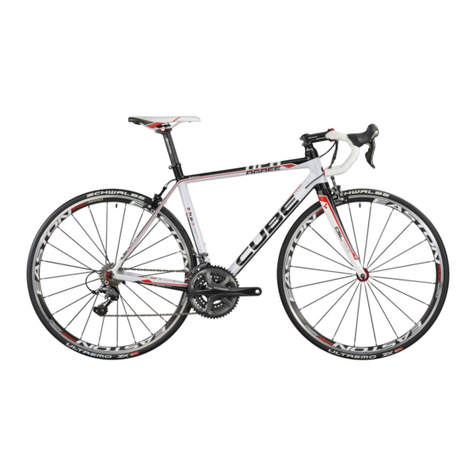
Cube SUPER HPC Operating instructions

Additional operating instructions:
Cube Carbon frame Super HPC, HPC + GTC
and (full) carbon forks CSL
HANDBOOK
SUPER HPC / HPC / GTC
ENGLISH

SUPER HPC /HPC/GTC
CUBE LITENING SUPER HPC SLT DURA
ACE DI2 2013
1 About this Owner‘sManual ........................................................................................... 04
1.1 Conventions ......................................................................................................................................... 04
1.1.1 Symbol ..................................................................................................................................................... 04
2 General Notes .................................................................................................................................. 04-05
3 Manufacturing process ............................................................................................................... 05
3.1 Road racing ........................................................................................................................................... 05
3.2 How to use your carbon parts correctly ........................................................................................ 06
3.3 Seat clamp/seat post ......................................................................................................................... 06
3.4 Front assembly .................................................................................................................................... 06
3.5 Headset .................................................................................................................................................. 06
3.6 Bottom bearing / crank inside bearing system ........................................................................... 07
3.7 Rear triangle ......................................................................................................................................... 07
3.8 Dropouts .............................................................................................................................................. 07
3.9 Bottle holder inserts ........................................................................................................................... 07
3.10 Roller training ....................................................................................................................................... 07
3.11 Transportation ...................................................................................................................................... 07-08
4 (Full) carbon forks) ........................................................................................................................ 08
5 Care instructions ............................................................................................................................ 08
6 Guarantee and special ex gratia settlements ................................................................. 08-09
7 Liability ................................................................................................................................................ 09
8 Quality Assurance and rigidity testing .............................................................................. 09
9 Assembly Instructions ................................................................................................................. 09
9.1 The MTB bike frame ............................................................................................................................ 10
9.2 The racing bike frame .......................................................................................................................... 11
Carbon Rigidity Test ........................................................................................................................ 12
Content
PICTURE
STEREO 650B SUPER HPC SLT 2013
PICTURE
IMPORTANT NOTES!
CUBE SUPER HPC, HPC + GTC
•This document must be read carefully prior to assembly and use of the frame/entire bike
and should be observed accordingly.
•These instructions are additional operating instructions for the Super HPC, HPC and GTC
Series and (full) carbon forks CSL.
•Please also observe the main Instruction Manual! If you do not have this please request it
from the dealer.

| 54 |
SUPER HPC /HPC/GTCSUPER HPC /HPC/GTC
3.1 Road racing
Danger of material damage!
Our frames are designed for extreme ri-
ding stresses. However during Road ra-
cing stresses greater than those occurring
during actual riding may arise as a result
of collision with objects or other riders.
These stresses cannot possibly be fore-
seen and allowed for in the construction
and design of a frame or forks. We there-
fore accept no liability for any damage re-
sulting from use other than that intended.
2.0 General Notes
Risk of Personal Injury and Material
Damage!
Failure to observe the instructions con-
tained in this Owner‘s Manual may re-
sult in dangerous riding situations, falls,
accidents and material damage.
Read through these instructions care-
fully before using your bicycle for the
rst time.
•Read through these instructions carefully
before using your bicycle for the rst time.
•Keep this Owner‘s Manual and pass it on
with the bicycle if you ever sell it or give it
as a present.
•It is your responsibility to check your bicycle
and to have any necessary work done to it.
•If you do not understand many of the sec-
tions of this Owner‘s Manual consult your
cycle dealer.
Carbon frames and (full) carbon forks are
lightweight construction components
which are manufactured in several pro-
duction steps using modern manufac-
turing procedures. The light weight is
achieved mainly by using high-perfor-
mance bre composite materials in con-
junction with an appropriate method of
bre construction. Component safety
and rigidity, in addition to low mass we-
re important criteria in the design of the
carbon frames and forks. Unavoidable
irregularities in the bre orientation
arising during manual procedures and
small air inclusions in the resin coating
layer or surface unevennesses are pure-
ly visual in nature and have no inuence
on the quality and performance of the
frame. Dierences in nish and “ble-
mishes” do not constitute grounds for
complaint.
Risk of Personal Injury and Material
Damage!
Irregularities of textile, like near-surface
minor air entrapments in the coating re-
sin or unevenness of the surface, which
cannot be avoided due to the process of
manufacture and handcraft,
3.0 Manufacturing process
Monocoque
Twin Mold Technology
In this process any folding jeopardising the
safety of the product is eliminated by con-
tinuous monitoring of the carbon bres
during the curing process. By additionally
using rigid inner formers at intersection
points the proportion of resin is conside-
rably reduced and the bres bonded more
tightly one to another. The result is incre-
ased product safety and improved rigidity
levels.
Advanced Twin Mold
In this process any folding endangering
the safety of the product is eliminated by
continuous monitoring of the carbon b-
res during the heat curing process.
This is guaranteed by an inner former
which gives the perfect frame shape ear-
lier in the layup process. Hence every in-
dividual bre remains in its exact position
during the curing process. This method of
manufacture makes it possible to increase
the carbon bre content within the frame
structure to match the design stresses.
The increased composite content means
that for the same stability there is less
weight in the form of resin and that the
frame has greater rigidity for less weight.
The positive side-eect of this method of
manufacture – perfect processing.
Dear Customer
We would like to thank you for your choice of a
bike from our Company and thank you for your
trust. With this purchase you have a high-quality,
environmentally friendly means of travel which
will give you a lot of pleasure and at the same
time promote your health.
Your cycle dealer is also very important to you
for advice and nal assembly. He is your point of
contact for servicing, inspections, modications
and all types of repairs. Should you have any
questions regarding our product please contact
your cycle dealer.
1 About this Owner‘s
Manual
1.1 Conventions
1.1.1 Symbol
Note!
Draws your attention to items requiring
your particular attention.
Warning!
Points out to you the possibility of slight
personal injury and possible material da-
mage.
Danger!
Points out to you the possibility of grave
personal injury even leading to death.
Torque
Also called tightening torque. Indicates
how “tight” a screw has been tighte-
ned.
Specialist
dealer /
specialist
workshop
In Germany: In this Owner’s Manual
the term “specialist dealer” and/or
“specialist workshop” indicates a dealer
trained as a bicycle mechanic and/or
cycle mechanic authorised by the com-
petent Chamber of Trade to operate a
specialist workshop.
Similarly the latter must be authorised
by the manufacturer of this cycle to
check and conrm correct assembly
and roadworthiness of this cycle.
Handforce
The force an average adult human can
exert with his hand using low to medi-
um eort.
Nm Newton meter; unit for torque
are only of optical kind and do not have
any eect on quality and performance of
the frame. Dierences in the nish and
disgurement are not a reason for any
warranty claim. Our carbon frames and
integral (full) carbon forks are approved
for a maximum system weight of 115 kg.
Maximum total weight
=
Bicycle including entire additional load
and attach parts
+
Body weight incl. clothing and baggage
(backpag)
Loadings deviating from the purpose of
use intended (e.g. jumps) may lead to
damage and constitute a risk to the user.
We accept no liability for damage arising
from improper use.
•It is not permissible to t additional com-
ponents to any frame or fork tubing which
is attached by means of clamping to the
tubing in question.
•Undened stresses in the circumferential
direction of the tubing considerable can
occur in this way which may cause damage
and which may drastically reduce the ser-
vice life, and may also lead to a risk to the
safety of the user.
•Basically every frame including forks must
be given a thorough examination at regular
intervals in respect of damage (e.g. cracks,
visible delamination, discolouration etc.).
•Shock and impact stresses may cause
damage not visible externally such as
delamination (separation of bres from the
surrounding plastic matrix) in the bottom
laminate layers causing a drastic reduction
in performance and consequently safety
as well. After any accident, crash or other
dened or uncontrolled mechanical stresses
the frame and forks must not be ridden for
reasons of safety and should be sent to us
for examination (see also Guarantee).
•With regard to accessories used the instruc-
tions or use and user guide provided by the
manufacturer concerned must be followed!
| 76 |
SUPER HPC /HPC/GTCSUPER HPC /HPC/GTC
3.5 Headset
Fully or semi-integrated headsets are used
in carbon frames for optimum rigidity values
and optimum distribution of forces and high
levels of security.
Risk of Personal Injury and Material
Damage!
Unauthorised milling work is not per-
missible and will result in the guarantee
being invalidated.
•Delivery is with headset installed. Any change
of headset must be agreed with the manufac-
turing company. Press-tting the headset shell
bearings must be performed using a specially
designed tool. Press tting must be performed
with caution and it must be ensured that the
shell bearings do not twist. The shell bearings
must not be greased at points where they are
in contact with the frame. The side facing the
bearing should be greased to ensure long life
of the headset.
3.4 Front assembly
Risk of Personal Injury and Material
Damage!
Racing bike frames are designed for either
a solder-on socket derailleur mounting or
for a classic derailleur clamp tting with a
34.9mm clamp - MTB frames have either
a classic 34.9mm derailleur clamp, direct
Mount or an E-type derailleur tting. No
other derailleur mountings may be used.
Maximum torque for tting the derailleur
clamp collar on the seat tube is 4 Nm and
must be tted in intermediate steps. When
tting a torque wrench it is important to
avoid deformation of the seat tube in the
vicinity of the clamp.
Damage to the seat tube in the vicinity of
the derailleur clamp by excessive tighte-
ning or incorrect size of clamp collar may
lead to safety-related deformation and
damage and must be avoided.
Rear triangle is designed for standard racing
bike brakes (or disc brakes in the case of the
caliper). The maximum permissible torque
when tting brakes is 8 Nm (min. 7 Nm). The
maximum permissible rear wheel disc size for
the carbon hardtail frame is 160mm and that for
the carbon Fully frame is 180 mm, or 160mmfor
the AMS Super HPC.
3.8 Dropout
The maximum torque for tting rear derailleur
to hanger is 8Nm (min. 7Nm (see Pages 11/12).
3.9 Bottle holder inserts
The threaded inserts on your carbon frame are
designed for xing standard bottle holders
with an M5 thread and other thread sizes are
impermissible.
3.10 Roller training
Risk of Personal Injury and Material
Damage!
The carbon frame must NOT be used for
roller training on so-called xed rollers
(Tacx, Elite, etc.).
•The use of bicycle rollers with xed clamps is
not permitted. By rmly restricting the drop-
outs and quick-release hub axles, mechanical
stresses occur which strongly exceed those
permitted for normal cycling operations. This
may result in damage to the bicycle frame.
3.11 Transport
Your carbon frame is a high-performance
lightweight product.
Risk of Personal Injury and Material
Damage!
Due care must be taken when trans-
porting wheels with carbon frames.
The frame should particularly be protec-
ted against contact with other parts using
a cover for example.
Please ensure that the bicycle is in a xed
and stable position during transport.
Transporting your carbon frame with
carrier systems which use clamping ele-
ments for xing and retaining the frame
tubes is impermissible as the clamping
forces of the xing elements can cause
damage to the frame/forks tubing
During transportation do not place any
objects on the frame and forks and stow
so that they cannot slip.
When transporting with the front or rear
wheel removed it is recommended that
a distance piece is inserted instead of
the hub in the rear assembly (racing bike
130 mm, MTB 135 mm) and in the forks
(100mm) in order to prevent damage.
3.3 Seat clamp/seat post
Risk of Personal Injury and Material
Damage!
The prescribed tightening torque of the
saddle clamp bolt is 5-6 Nm.
The seat tube must not be scoured or me-
chanically processed in any other way.
Please consult your authorised specialist
retailer immediately after a fall.
The seatposts and seat tubes must not be
lubricated. Only a carbon assembly paste
may be used.
3.6 Bottom bearing / crank inside
bearing system
The bottom bearing must be tted using
a tool specially designed for the task. Only
bottom bearing and crank inside bearing
systems designed for „Presst“ types may be
used. The Presst inner bearing must only be
press-tted using the tool specially designed
for the purpose.
3.7 Rear triangle
Your carbon frame rear assembly has be-
en designed and built for a hub width of
130 mm (racing bike) and 135/142mm (MTB
Hardtail +MTB-Fully).
Risk of Personal Injury and Material
Damage!
On the rear triangle only hubs of 130mm
(racing bike) and 135 mm (MTB-hardtail)
and a quick-release mechanism must
be used. For the Fully models 135mm a
quick-release mechanism and a 142mm
Syntace X12 axle.
The use of hubs with other dimensions
and/or without quick-release mechanism
may result in stress and distension condi-
tions, which can lead to serious damage
and therefore present a risk to safety. The
rear assembly is designed.
Frame and forks must be examined parti-
cularly carefully for damage (e.g. cracks,
delamination, discolouration etc.) before
and after each instance of use in racing.
After serious crashes or accidents the
frame and forks must not be ridden. The
surface of the frame and forks must not be
damaged. This includes indentations and
large deep scratches which penetrate bey-
ond the rst clear coat of lacquer. In case
of doubt the frame and forks must be sent
in for checking.
3.2 How to use your carbon parts correctly
Risk of Personal Injury and Material
Damage!
1. Do not, under any circumstances, mount
brackets, screws, clamps or other elements
which exert mechanical pressure on the
carbon tube.
2. Clamping onto bike stands or other wall
brackets:
•Never clamp your bicycle around the carbon
tube or carbon seatpost in the clamping jaws
of a bike stand.
3. Please take care when using shackle locks!
These may, under certain circumstances,
cause damage to your frame.
•When using shackle locks, please ensure that
these only touch the respective carbon tube
at the most, and are not exerting pressure.
Aluminium seatposts may only be moun-
ted using a carbon assembly paste.
The seat clamp may not be closed if the
seat post has been removed.
The maximum torque of bottle holder xing
screws is 4 Nm (min.3Nm) (see Pages 11/12).
Carbon frames are approved for bottle holders
which can take a 750 ml capacity bottle.

| 98 |
SUPER HPC /HPC/GTCSUPER HPC /HPC/GTC
6.0 Guarantee and special ex gratia
settlements
Services under the guarantee are provided
only in the event of faulty materials or manu-
facture and never in the event of fatigue or
overload stress damage. We provide 3 years
guarantee on our frames and forks and we
also oer special ex gratia services.
Risk of Personal Injury and Material
Damage!
Ifyoudiscoverdamagetoyourframeand/or
forksyoumaysendthedamagedframeand/
orforksto usforassessment andanestima-
te of possible repair costs via your dealer.
Transport costs in every case are borne
by the customer. Following assessment of
repair costs the repair is carried out either
freeofchargeoryouwillreceiveanadvance
estimate of repair costs.
4.0 (Full) carbon forks)
Our full carbon forks and carbon forks with
aluminium steerer have a shaft diameter
of 1 1/8” in the clamp area one of the stem.
Near the lower bearing race the forks ts the
following headset sizes; 1 1/8”, 1 ¼” or 1 ½”.
Only headsets and stems which are designed
or approved according to the frame and fork
specication by the bike manufacturer may
be used.
Risk of Personal Injury and Material
Damage!
If the headset bearing lower cone ring
is driven into the bearing seat with mas-
sive force there is a danger of dama-
ging the forks. Fitting a headset must
be carried out by a specialist technici-
an. The shaft tube external diameter in
the vicinity of the stem is designed for
front extensions with a clamp diameter
of 1 1/8”. Only the handlebar stems with
corresponding internal dimensions and
cleanly nished interior surfaces may be
used. The tted stem may project no mo-
re than a maximum of 2 mm above the
edge of the shaft tube end.
•The front brake is tted to the forks using the
special screws supplied by the manufacturer
with an M6 thread with an internal hexagon
(Allen screw®) head. (SW 5mm). The external
diameter of the nuts must not exceed 8 mm
and the maximum torque of the nuts is 8Nm
(min. 7 Nm)
Risk of Personal Injury and Material
Damage!
Carbon forks with a steerer made of alu-
minium may be assembled with a so
called “star-nut” in order to adjust the
headset . When doing this the fork should
not be assembled on hard surface in order
not to damage the fork.
In this case the provided so called “expan-
der” or “thread insert “ must be used on
a full carbon fork. The use of a so called
“star-nut” on a full carbon fork will lead
to a serious damage of the steerer tube or
dangerous failure of the fork. The length of
the steerer tube can only be cut to size by a
professional bicycle mechanic.
•Ideally a metal saw with low abrasion rate or
a metal circular saw with a diamond saw bla-
de and water cooling should be used.
•In the event of dry trimming adequate
protection from dust inhalation produced
should be ensured. Inhalation protection
with a ne dust lter and safety glasses are
recommended.
5.0 Care instructions
Your carbon frame and your (full) car-
bon forks should be cleaned regular-
ly. Ordinary paint care products with or
without silicon additive and cold to lu-
kewarm water to which may be added
ordinary detergent may be used. To be
avoided are solvents of any description,
alcohols (e.g. ethanol or isopropanol), hot
water with alkaline additives or cleaning
with steam jets and pressure washers.
7.0 Liability
Risk of Personal Injury and Material
Damage!
The manufacturing company accepts no
liability for accident damage or conse-
quential loss. The user bears the risk in
the event of personal injury and material
damage. The manufacturing company ac-
cepts no liability for damage or accidents
caused by improper use of the frame and
failure to comply with the stipulations in-
dicated here.
8.0 Quality Assurance and rigidity testing
•Every carbon frame ready for delivery and
every set of full carbon forks are subjected to
a rigidity test.
When travelling by air or on journeys
where the “bicycle“ luggage item is not
checked with regard to damage-free sto-
wage, adequate protection of the frame
and forks must be ensured (e.g. by using
suitable hard-top cases etc.)
The decision as to whether a repair is to be
carriedoutfreeofchargerestssolelywiththe
manufacturing company and in no circum-
stancesisthereanyclaimtocost-freerepair.
The special ex gratia provisions only ap-
ply to the rst owner.
Only cleaned frames or forks are accepted
for guarantee work!
•In the event of frame or fork complaint
claims we reserve the right to apply a
reduction in value based on the duration
of use.
Risk of Personal Injury and Material
Damage!
The guarantee is rendered invalid in the
case of damage, which is attributable to
incorrectassembly,misuse,unauthorised
modications or mechanical working of
frames and fork components (drilling,
milling, ling, sawing etc, on frames or
forks manufactured by us.
Thenaldecisionastowhatextentaclaim
under the guarantee exists is a matter for
the management of the manufacturing
company.
•For each frame height and each set of forks
a rigidity tolerance range is dened in preli-
minary testing. Only frames and forks which
come within this tolerance range leave the
factory.
•The rigidity test is used as a Quality Assu-
rance measure and is performed on the
company’s own test rig. To do this the frame
to be measured is xed in place at the rear
assembly and the steering tube. Then the
gear crank area is deected to one side using
a dened force delivered by a pneumatic cy-
linder. As a second step rigidity measurement
of the steering pipe occurs through targeted
torsion of the steering head to the frame.
The rigidity values arise from the ratio of the
applied force and the resulting deection
of the frame area and are documented on
the test sticker in the operating instructions
enclosed.

| 11
SUPER HPC /HPC/GTC
10 |
9.0 Assembly Instructions
9.1 The MTB bike frame
9.2 The racing bike frame
Seat post assembly
Consider max. allowed seat post length (x)
including min. insert length (y):
120 mm (y) at 400 mm (x)
120 mm (y) for adjustable seat post (e.g.
RockShox Reverb) with max. 420mm (x)
110 mm (y) at 380 mm (x)
100 mm (y) at 350 mm (x)
Seat post assembly
Consider max. allowed seat post length
(x) including min. insert length (y):
100 mm (y) at 350 mm (x)
80 mm (y) at 300 mm (x)
Brake mount screw(s)
Max. 8 Nm
Rear derailleur mount screw
Max. 8 Nm
Rear derailleur mount screw
Max. 8 Nm
Brake mount screw
Max. 8 Nm
Bottle cage assembly screws
Only M5 screws are allowed.
Max. 3Nm
Bottle cage assembly screws
Only M5 screws are allowed.
Max. 3 Nm
For seat post assembly apply carbon assembly paste
(e.g. from Dynamix, Syntace, …) to seat post and to the
inside of seat tube. It is not allowed to use standard
grease!
Consider torque on seat clamp and seat post!
Max. 6 Nm
Apply torque gradually!
Cable stop screws
Max. 1,5 Nm
Front derailleur mount screw
Band type Max. 4Nm / Min. 3 Nm (apply gradually)
E-direct Max. 7Nm / Min. 5 Nm (apply gradually)
Direct Mount Max. 7Nm / Min. 5 Nm (apply gradually)
Bottom bracket
Use only suitable „Presst“ bea-
rings. Special tools for assembly
and disassembly of “Presst”
bearings are necessary. Grease
is only allowed on frames with
alloy tube.
Front derailleur mount screw
Band type Max. 4 Nm / Min. 3 Nm
(apply gradually)
Brazed-on type Max. 4 Nm / Min. 3 Nm
(apply gradually)
Brake mount screw
Max. 8 Nm
Head set assembly (integrated
/ semiintegrated) Special tools
for assembly and disassembly
of head set or head set cups are
necessary. Usage of grease is not
allowed!
Head set assembly (integrated
/ semiintegrated) Special tools
for assembly and disassembly
of head set or head set cups are
necessary. Usage of grease is not
allowed!
For seat post assembly apply carbon assembly paste
(e.g. from Dynamix, Syntace, …) to seat post and to the
inside of seat tube. It is not allowed to use standard
grease!
Consider torque on seat clamp and seat post!
Max. 6 Nm
Apply torque gradually!
Bottom bracket
Use only suitable „Presst“ bea-
rings. Special tools for assembly
and disassembly of “Presst”
bearings are necessary. Grease
is only allowed on frames with
alloy tube.
SUPER HPC /HPC/GTC

12 |
SUPER HPC /HPC/GTC
Carbon Rigidity Test
The following data are of importance for any possible guarantee or war-
ranty claims in the event of an exchange frame in the context of our Crash
Replacement Program. Please keep the datasheet in a safe place.
Frame or (full) carbon forks measurement result:
Other manuals for SUPER HPC
2
This manual suits for next models
1
Table of contents
Other Cube Bicycle manuals

Cube
Cube Kids 120 User manual

Cube
Cube EPO pedelec User manual

Cube
Cube Road bike User manual

Cube
Cube Mountain Bike User manual

Cube
Cube SUPER HPC Operating instructions

Cube
Cube MTB User manual

Cube
Cube STEREO HYBRID 120 User manual

Cube
Cube Kinder Bmx User manual

Cube
Cube AERIUM Series User manual

Cube
Cube SUPER HPC Quick start guide