JOBOBIKE Bruno User manual

USER MANUAL
Bruno

2
About Us
Dear Sir/Madam:
JOBOBIKE has been present on the bikes market
for two decades. We have been producing bikes
for well-known worldwide clients’ brands. Helping
others to succeed has resulted in our own success.
Today, we are one of the leading companies in
the electric bikes industry. After many years of
hard work, it’s time to shift our identity: from
being an “E-bike supplier” to become “JOBOBIKE.”
The knowledge we have gathered allows us to
create distinctive electric bikes that are built to suit
the modern lifestyle. We offer incredible biking
experience, ensuring competitive prices.
Your faithfully
Muriel.H
Member of the Management Board of JOBO Group

3
Just biking with JOBOBIKE
No matter where you are and where you’re
heading to, our bikes fit your lifestyle. City or
countryside, flat or rocky roads, our bikes will get
you there. Moreover, our lifetime customer service
is always with you.
Our Values
J
O
B
O
Joy of life full of new experiences
Opportunity to bike further
Biking without limitations
Options of transport

4
Manual Use Instruction Table Of Content
This manual contains the details of the
equipment, operation, and maintenance of
the product along with our advice to you.
Before you start using your new bike, it is
necessary to read through the instructions.
If you are unclear about any steps, you can
always find additional information and
instructions on our website:
About Us ............................................................2
Our Values..........................................................3
Manual Use Instruction ......................................4
Table Of Content ................................................4
English Installation Guide
General Information...........................................6
Assembly Instructions ........................................8
Operation Instruction ....................................... 12
Cautions........................................................... 16
Error Code Definition........................................ 18
Warranty Terms ................................................ 20
Main parameters of E-bike ............................... 21
www.jobobike.eu

5
Guide d'Installation en français
General Info ..................................................... 22
Aufbauanleitung.............................................. 24
Betriebsanleitung............................................. 28
Vorsichtsmaßnahmen ...................................... 32
Fehlercode-Definition ...................................... 34
Garantie ........................................................... 36
Hauptparameter des E-Bikes............................ 37
Guide d'Installation en français
Informations Générales ................................... 38
Instructions d’assemblage ............................... 40
Instruction d’opération..................................... 44
Précautions ...................................................... 48
Définition du code d’erreur .............................. 50
Garantie ........................................................... 52
Main parameters of the E-bike ......................... 53
Instrukcja montażu w języku angielskim
Informacje Ogólne ........................................... 54
Instrukcja montażu........................................... 56
Obsługa wyświetlacza ..................................... 60
Środki ostrożności ............................................ 64
Kody błędów .................................................... 66
Gwarancja........................................................ 68
Specyfikacja roweru ......................................... 69
Terms and Conditions
General provisions ...........................................70
Services............................................................ 70
Delivery............................................................ 72
Complaints for the goods under warranty........ 72
Disclaimer ....................................................... 73

6
General Info
The manual is a basic instruction for assembling and using your bike. To ensure proper use and trouble-free operation,please
read this manual carefully and follow the instruction. If you still need help, please visit our website, contact us by email, or call
us for more information.
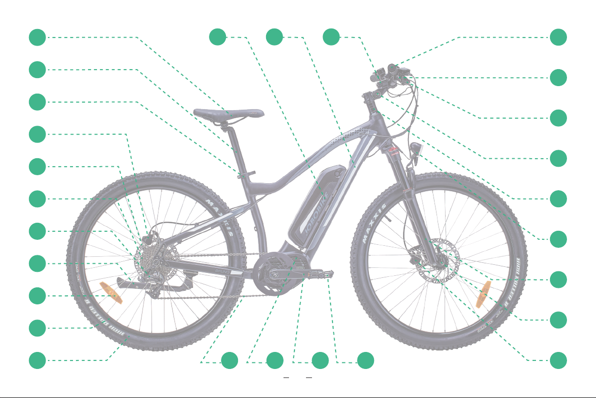
BRUNO is a 250 watt e-bike. Please follow all relevant laws and regulations in your country or region when riding this ebike.
NO. Accessory name NO. Accessory name NO. Accessory name
1 Saddle 10 Rim 19 Front light
2 Seat post 11 Tyre 20 Headset
3 Seat post clamp 12 Chain 21 Stem
4 Rear brake 13 Middle motor 22 Shifter
5 Hydraulic Brake rotor 14 Crank 23 Brake lever
6 Freewheel 15 Pedal 24 Grips
7 Rear Derailleur 16 Front brake 25 Display
8 Kickstand 17 Quick release 26 Frame
9 Reflector 18 Suspension fork 27 Battery

7
125
1312
26 27
14 15
2
3
4
5
6
24
7
23
8
22
9
21
10
20
11
19
18
17
16

8
Assembly Instructions
Step 1 Unpack the bike
Open the package and take out all of the parts.
Be careful of not missing even a little piece of part.
The parts shall include:
Install the handlebar to the stem and fix it with matching
screws by a 4# hexagon wrench. During installation, adjust
the handlebar to an appropriate angle so that the bicycle
can be operated comfortably. Make sure the four screws are
tightened enough and the handlebar cannot be moved.
Step 2 Unfold the kickstand to
make the E-bike stand up
Step 3 Install the handlebar
Front Wheel Charger
Assembly Toolkit Keys (2 identical)
Front wheel axle Headlight
Manual Pedals
Display

9
Step 4 Install the front wheel
Step 5 Install the front fender
and headlight
4. 1 Place the front wheel in the correct position of the fork
groove and tighten it with matching wheel axel.(if there are
any hub protection parts attached to the wheel, remove
them)
4. 2 Make sure the front wheel will not rub the brake pads
when it is rotating under the condition of not pinching
brake handle.
5.1 Install the front fender and headlight to the front fork
with matching screws and nuts by a 4# hexagon wrench.
Make sure the front fender and headlight support cannot
be moved.
5.2 Adjust the headlight to a proper angle by this way:
loosen the adjusting bolt with a cross-head screwdriver,
adjust the headlight tilt angle to the best position, and then
tighten the bolt.
5.3 Connect the cable plug to the headlight, please note to
align the inner pins and notches with the outer arrows.

10
Step 6 Adjust the saddle height
Step 7 Adjust the saddle angle
or position
Step 8 Install the pedals
Move the saddle up or down to your desired saddle height.
Do not raise the saddle post exceeding the minimum
insertion mark on the saddle post. Close the quick release
lever and make sure the lever is tighten enough when
locking the saddle post.
Release the screw with a 6# hexagon wrench and then
you can move the saddle to the left or right to change the
position. Also you can change the angle of the saddle at
the same time to make it more comfortable while riding.
The “L” mark refers to the left pedal.
The “R” mark refers to the right pedal.
Tighten the right pedal clockwise and tighten the left pedal
anticlockwise with the 15# wrench.
Note: please carefully thread each pedal into its
appropriate crank set.

11
Schrader valveSchrader valve
Minors are prohibited from riding
NOTICE: Both wheels must be properly settled
before operating your bike. If you are not able
to assemble your bike, please contact us or
look for help from a certified, reputable local
bike mechanic. Ensure all hardware is tightened
properly. Also ensure that all safety checks in the
following sections are performed before the first
use of the bike.
!
Step 9 Inflate the tyres
Check whether the tyres beads and tyres are evenly seated
on the rims. Use a pump with a Schrader valve and pressure
gauge to the recommended pressure indicated on the tyre
sidewall. 35-60 psi (2.5 – 4.1 bar).
Note: Do not over inflate or under inflate tyres.

12
1. Up
2. Light On/O
3. System On/O
4. Ok/Enter
5. down
1. Display Remote
2. Bell
3. LCD Display
4. Shifter
5. Brake
Operation instruction
1
1 3 4
2
5
2
3
4
5

13
① Time
②USB charging indicator displays the icon,if an external
USB device is connected to the display.
③The display shows this symbol, if the light is
on.
④Speed Graphics
⑤Trip: Daily kilometers (TRIP) - Total kilometers
(ODO) - Top speed (MAX) - Average speed(AVG)
- Range (RANGE) - Energy Consumption
(CALORIES(only with torque sensorfitted)) - Travel
time (TIME).
⑥Display of battery capacity in real time.
⑦Voltage indicator in voltage or in percent.
⑧Digital speed display.
⑨Power indicator in watts / amperes.
⑩Support level/ Walking assistance
⑪Data: Display data, which corresponds to the
current mode.
⑫Service: Please see the service section

14
1.Hold the power button for about 2s to switch on /o the
E-bike.
2.The E-bike will switch o automatically after 10 minutes
of inactivity.
3.The display interface shows Time,Speed, Light indicator,
Battery SOC, USB indicator, ODO, Power assistance level,
Walking assistance mode, Trip Distance.
4.Hold the Headlight switch key button for about 2s to turn
on the front light ( The brightness of display back light will
automatically decrease ).
Hold the Headlight switch key button for another 2s to turn
off the front light (The display back light will recover its
brightness).
The screen shows the indicator when you turn on the
front light.
5.Short press the “ i ” button to cycle the functions below:
single-trip distance (TRIP) →total distance ODO→maximum
speed (MAX) →average speed (AVG) →remaining distance
(RANGE) →energy consumption (CALORIES) →time (TIME).
6.Short press“+”button to add the power assistance level
→0 →1 →2 →3 →4 →5
Short press“-”button to minus the power assistance level
5→4 →3 →2 →1 →0 →
when in the push-assistance mode, hold the “-” button for
about 2 seconds to activate the push-assistance function
and the push-assistance function will be switched off as
soon as you release the “-”button. The speed is about 6
Km/h when in the mode of Push-assistance.
Power assistance Level “0”:The minimum power
assistance level (No assistance provided.)
Power assistance Level “1”:The default power assistance
level when switching on the E-Bike.
Power assistance Level “5”:The maximum power
assistance level.
7.Clench the brake lever to slow down or stop the E-bike.
8.Switch the shifter by“+ "and“-”button to adjust the speed
for fitting with dierent road conditions.

15
Put the battery into the frame and turn the key to the right
to lock the battery. ( take good care of your keys )
Open the cover and plug the charger into the battery
socket.
The five battery bars represent the capacity of the battery.
Turn the key to the left to
unlock the battery, then get
the battery out. ( take good
care of your keys )
Install the battery Charge the battery
Battery SOC Indicator
Remove the battery

16 16
(1) Make sure the front and rear brakes are sensitive, and
the brake pads are not seriously worn (more than 1/3).
(2) Make sure the tire pressure is sucient and the tire is not
seriously worn.
(3) Make sure the mechanical parts are not broken or loose
especially the handbar, front fork and wheels. make sure all
bolts and fasteners are fastened enough.
(4) Make sure the disc brake disc is not cracked or deformed,
make sure the chain does not touch the wheel.
(5) Make sure that the battery has enough power and the
battery has been firmly stuck in the battery compartment.
(1) Turn the throttle slowly when starting the bike. Starting
too fast will cause excessive current and aect the service
life of components.
(2) Frequent braking and starting shall be minimized to
save electric power consumption and prolong the working
life of electrical components.
Check before riding
Tips duringthe riding
Cautions
(1) The bike frame needs to be wiped up for the long-term
storage. Lubricate the flywheel, chain and chain puller
if these parts are lack of lubricating oil.Repaint the bike
frame to prevent rusting if the frame is scratched.
(3) In order to reduce the current of the electrical
components, it is better to use pedal assistance when
riding on steep slopes.
(4) Stop the bike immediately for inspection when the bike
makes abnormal noise during the riding.
(5) To slow down or stop the bike we recommend you to
operate the rear brake first, and then operate the front
brake.
(6) In rainy or snowy weather, kindly suggest to take the
brake slowly in advance rather than taking a sudden brake.
(7) It is recommended to ride in good weather and road
conditions. Do not riding in heavy rain, otherwise the
water will get into the display, battery and other electrical
components and cause failure.
(8) Please follow the local trac rules, take safety measures
and wear safety helmets when riding.
(9) Do not ride an bike when you are in poor health.
Precautions for long-term storage

17
16
(1) Make sure the battery and charger are not damaged
when using.
(2) Make sure the battery and charger stay far away from
the environment of fire, immersion, overheating, high
humidity,violent vibration, collision etc.
(3) Make sure the outer substance especially the metal sta
will not penetrate into the charger.
(4) Make sure the charger is being used at rated voltage
and frequency.
(5) Disconnect the charger immediately from the power
supply socket when the charger is in the state of sparks,
smoke and other abnormal conditions.
(6) Make sure the battery is not being stored in the state of
low power.(Charge the battery for every 3 months ).
(7) Make sure the battery is not being excessively
discharged and charge the battery in time when it is
Battery and charger operation
(2) The bike shall be stored in a dry, cool and tidy place.
(3) Turn o the power button to cut o the battery power if
there is a power button on the battery.
running out of power.
(8) Make sure the battery is not being excessively charged
and cut off the power in time when the battery is full of
power(led indicator turns green).
(9) Make sure the charger you used is provided by JOBOBIKE
and it can only be used to charge the matched bike battery.
(10) The battery shall be placed in a dry and cool
environment when charging.
(11) Make sure the battery and the charger are being
repaired by the professional if there are break down.

Error code definition
Error Code Definition Solution
07 High voltage protection
1. Remove and re-insert the battery to see if it resolves the problem.
2. Use the BESST tool to update the controller.
3. Change the battery to resolve the problem.
08 Fault with motor hall sensor inside 1. Check if all connectors from the motor are correctly connected.
2. If the problem still occurs, please change the motor.
09 Error with the Engine’s phases Please change the motor.
10 The motor temperature reachesthe max
protection value
1. Turn o the system and allow the Pedelec to cool down.
2. If the problem still occurs, please change the motor.
11 The temperature sensor inside the motor
has an Please change the motor.
12 Error with current sensor inside controller Please change the controller or contact your supplier.
14
The protection temperature inside the
controller has
reached its maximum protection value
1. Allow the pedelec to cool down and then restart the system.
2. If the problem still occurs, please change the controller or contact your
supplier.
15 Error with the temperature sensor inside the
controller
1. Allow the pedelec to cool down and restart the system.
2. If the problem still occurs, please change the controller or contact
yoursupplier.
21 Error with wheel speed detecting sensor
1. Restart the system
2. Check that the magnet attached to the spoke is aligned with the speed sensor
and
that the distance is between 10 mm and 20 mm.
3. Check that the speed sensor connector is connect correctly.
4. Connect the pedelec to BESST, to see if there is a signal from the speed
sensor.
5. Using the BESST Tool- update the controller to see if it resolves the problem.
6. Change the speed sensor to see if this eliminates the problem. If the problem
still
occurs, please change the controller or contact your supplier.

19
Error Code Definition Solution
25 Torque signal Error
1. Check that all connections are connected correctly.
2. Please connect the pedelec to the BESST system to see if torque can be read
by
the BESST tool.
3. Use the BESST Tool to update the controller to see if it resolves the problem, if
not,
please change the torque sensor or contact your supplier.
26 Speed signal of the torque sensor has an
error
1. Check that all connections are connected correctly.
2. Please connect the pedelec to the BESST system to see if speed signal can be
read
by the BESST tool.
3. Change the Display to see if the problem is solved.
4. Use the BESST Tool to update the controller to see if it resolves the problem, if
not,
please change the torque sensor or contact your supplier.
27 Over current from controller
Use the BESST tool to update the controller. If the problem still occurs, please
change
the controller or contact your supplier.
30 Communication problem
1. Check if all connections on the pedelec are correctly connected.
2. Use the BESST Tool to run a diagnostics test, to see if it can pinpoint the
problem.
3. Change the display to see if the problem is solved.
4. Change the EB-BUS cable to see if it resolves the problem.
5. Use the BESST tool to re-update the controller software. If the problem still
occurs,
please change the controller or contact your supplier.

20
Non warranty terms
We will not provide the warranty item with the following
conditions.
(1) The customer is unable to provide valid frame serial
number.
(2) The whole bike and parts have exceeded the warranty
period.
(3) Failure or damage caused by unauthorized private
modification or maintenance.
(4) Failure or damage caused by the usage of accessories
that not designated by Jobobike.
(5) Failure or damage caused by incorrect installation,
usage and operation.
(6) Failure or damage caused by the using of the product in
a non-specified working environment.
(7) Normal wear and tear of the tires, brakes and pedals
are not covered by the warranty.
(8) Failure or damage caused by irresistible factors(such as
fire, earthquake, lightning, flood, etc.).
Warranty
JOBOBIKE provides 24 months limit warranty for all
customers. The after-sales service cycle starts from the date
of product delivery. The customer shall bear the postage
required for parts delivery.
In case of non-human damage to the product during the
warranty period, JOBOBIKE will provide free replacement
parts or remote after-sales support, and the special
problems will be solved by both parties through
negotiation.
The repair parts may be non-new parts, but our company
guarantees that the functions of the parts are completely
normal.
Accessories category and warranty period:
(1) Frame and front fork: 5 years.
(2) Motor, controller, battery, charger, display, light,
handlebar, etc.: 2 years.
Other manuals for Bruno
1
Table of contents
Languages:
Other JOBOBIKE Bicycle manuals

JOBOBIKE
JOBOBIKE VIVA User manual

JOBOBIKE
JOBOBIKE Eddy-X User manual

JOBOBIKE
JOBOBIKE COMMUTER User manual

JOBOBIKE
JOBOBIKE Henry User manual

JOBOBIKE
JOBOBIKE ROBIN User manual

JOBOBIKE
JOBOBIKE Linda User manual

JOBOBIKE
JOBOBIKE Henry User manual

JOBOBIKE
JOBOBIKE ROMER User manual

JOBOBIKE
JOBOBIKE TRANSER User manual

JOBOBIKE
JOBOBIKE Linda&Lyon User manual