CUDA 1.043-342.0 User manual

For technical assistance or for the dealer nearest you
visit our website at www.CudaUSA.com
2518
PARTS WASHER
■ 1.043-342.0 ■ 1.043-343.0 ■ 1.043-344.0
■ 1.043-381.0 ■1.043-380.0 ■1.043-345.0
8.915-630.0
CHECK
WATER LEVEL
DAILY
CAUTION
HOT ALKALI
DO NOT USE
FLAMMABLE
SOLUTIONS
DO NOT
OPEN WHILE
PUMP IS
RUNNING
89156300-1
9.801-125.0
ATTENTION
USE ONLYCUDA APPROVED
DETERGENTSTO EXTEND
LABORWARRANTY TO 1-YEAR!
MIXDETERGENTS 1 LB (1/2 KG) PER
5-GALLONS(15 LITERS) OF WATER
ForCU DAApproved Detergents visit
http://www.cudausa.comor
call 888-319-0882
9.807-513.0
90-DAYLABOR WARRANTY
EXTENDSTO 1-YEAR
WITHEXCLUSIVE USE OF
CUDADETERGENTS
LIMITED


3
CONTENTS
CUDA 2518 • 8.915-630.0 • Rev. 7/13
SECTION 1
Introduction and Safety
Owner Responsibility 5
General Safety Information 5
Component Identifications 6-7
SECTION 2
Installation
Before you Begin 8
Electrical Connections 8
Connect a Compressed-Air Line and Accessories 8
Step 3: Fill the Machine with Water and Add Detergent 8-9
SECTION 3
Operation
Main Operating Components 10
Control Panel 10
Lid Safety Switch 10
Thermostat 10
Debris Screen 10
Air Flow Valve 11
Power Brush 11
Detail Brush and Flow Regulator 11
Oil Skimmer System 12
Low Water Shut-off 12
Automatic Water Fill 12-13
Detergent Concentration 13
Preparing the Machine for Use 13
Washing Parts 13
Shutting Down the Machine 13
SECTION 4
Troubleshooting
Overview 14-16
Troubleshooting the Electrical System 17
Testing Individual Components 18-19

CONTENTS
4
Model Number ______________________________
Serial Number ______________________________
Date of Purchase ____________________________
The model and serial numbers will be found on a decal attached to
the parts washer. You should record both serial number and date
of purchase and keep in a safe place for future reference.
CUDA 2518 • 8.915-630.0 • Rev. 7/13
SECTION 5
Maintenance and Repair
Maintaining the Machine 20
Daily Maintenance 20
Weekly Maintenance 20
Monthly Maintenance 20
Semi-Annual Maintenance 20
Using the Oil Skimmer System 20
Cleaning and Aligning the Spray Nozzles 20-21
Repairing the Machine
Heating Element 21-22
Thermostat 22
Turntable Motor 22-23
Timers and Switches on the Control Panel 23-24
Skimmer Motor 24-25
Exploded Views & Parts Lists
Front Exploded View and Parts List 26-27
Spray Arm Exploded View and Parts List 28-29
Rear Exploded View and Parts List 30-31
Options Exploded View and Parts List 32-33
Electrical Panels, Exploded Views and Parts Lists 34-45
Filtration with Sump Sweep Exploded View and Parts List 46-47
Factory Installed Filtration Exploded View and Parts List 48-49
Oil Skimmer Exploded View and Parts List 50
Warranty

CUDA 2518 • 8.915-630.0 • Rev. 7/13
5
PARTS WASHER OPERATOR’S MANUAL
This manual is intended as a guide for safely install-
ing, operating and maintaining your automatic parts
washer system.
We reserve the right to make changes at any time
without incurring any obligation.
Owner/User Responsibility:
The owner and/or user must have an understanding
of the manufacturer’s operating instructions and warn-
ings before using this machine. Warning information
should be emphasized and understood. If the operator
is not fluent in English, the manufacturer’s instructions
and warnings shall be read to and discussed with
the operator in the operator’s native language by the
purchaser/owner, making sure that the operator com-
prehends its contents.
Owner and/or user must study and maintain for future
reference the manufacturers’ instructions.
SAVE THESE INSTRUCTIONS
This manual should be considered a permanent
part of the machine and should remain with it if
machine is resold.
When ordering parts, please specify model and se-
rial number. Use only identical replacement parts.
This machine is to be used only by trained
operators.
GENERAL SAFETY
INFORMATION
CAUTION:To reduce the risk of
injury, read operating instruc-
tions carefully before using.
1. Read the owner’s manual
thoroughly. Failure to follow in-
structions could cause a mal-
function of the parts washer
and result in death, serious
bodily injury and/or property
damage.
2. Improper installation could cause serious injury
to the machine. All installations must comply with
local codes. Contact your electrician, plumber,
utility company or the selling distributor for specific
details.
3. The machine can only operate on the type of electri-
cal power indicated on the electrical specifications
tag. Operating the machine on any other power
supply will permanently damage the motors.
WARNING
READ OPERATOR’S
MANUAL
THOROUGHLY
PRIOR TO USE.
WARNING: Electrical shock
could cause serious injury or
death.
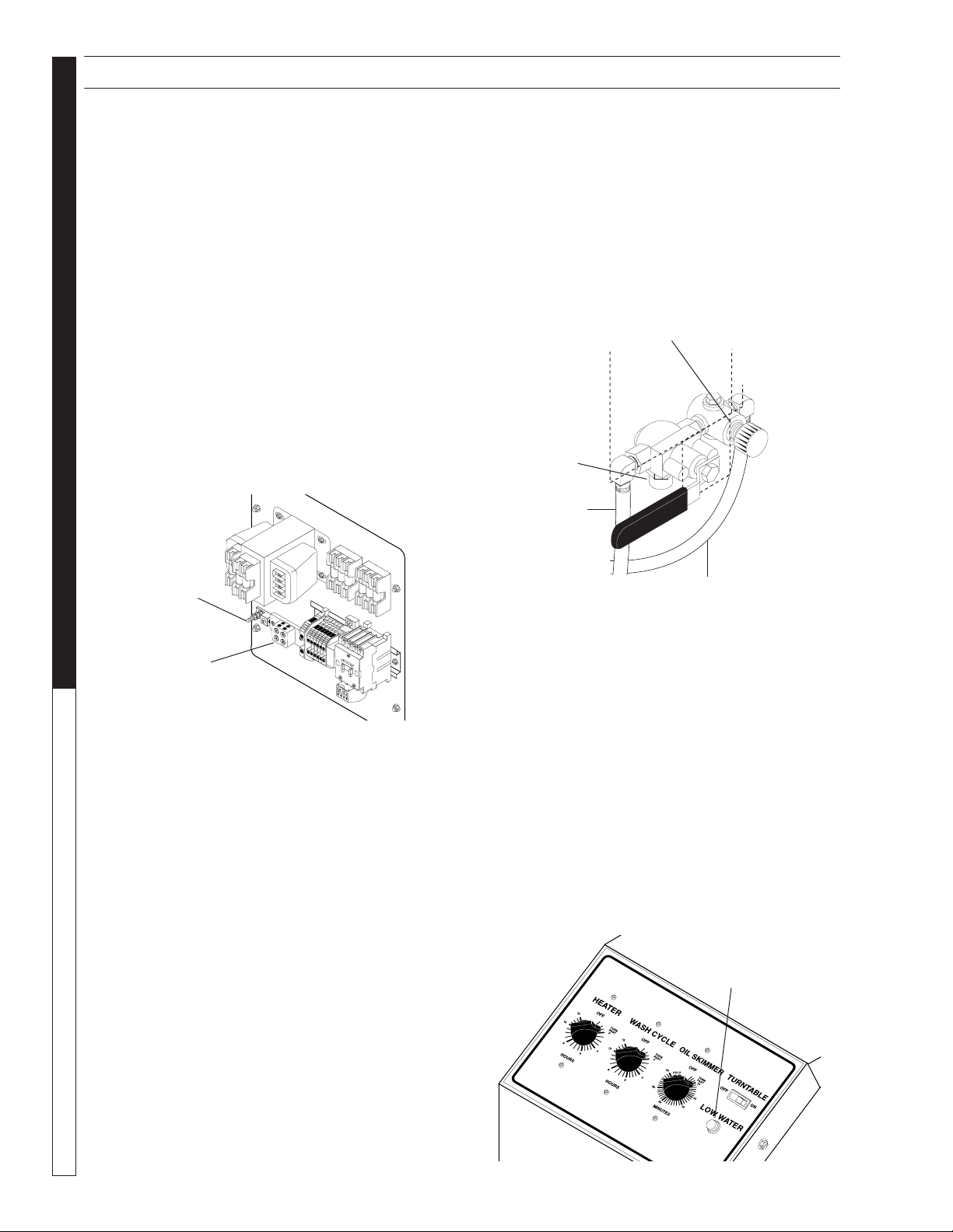
4. Install the machine in compli-
ance with the National Electric
Code, connect it to a properly
sized lockable disconnect and
ground the machine using
the grounding stud inside the
main electrical panel.
5. While operating the machine, keep all electrical
panels in place and securely fastened at all times.
6. Disconnect the machine completely from the out-
side power source before servicing.
WARNING: Hot, high pressure
cleaning solution could cause
serious injury.
7. Do not operate the machine
with the lid or door open and
do not override the safety
switch.
8. After the machine stops, wait
10 seconds before opening
the lid or door.
WARNING: Always wear ap-
proved eye protection and pro-
tective clothing while operating
machine.
9. Always wear rubber gloves
when loading and unload-
ing the machine or servicing
components in the processing
chambers or sumps.
WARNING: Slips and falls could cause serious
injury.
10. Maintain an unobstructed work area around the
machine and keep the floor free of water, oil, grease
or other foreign substances.
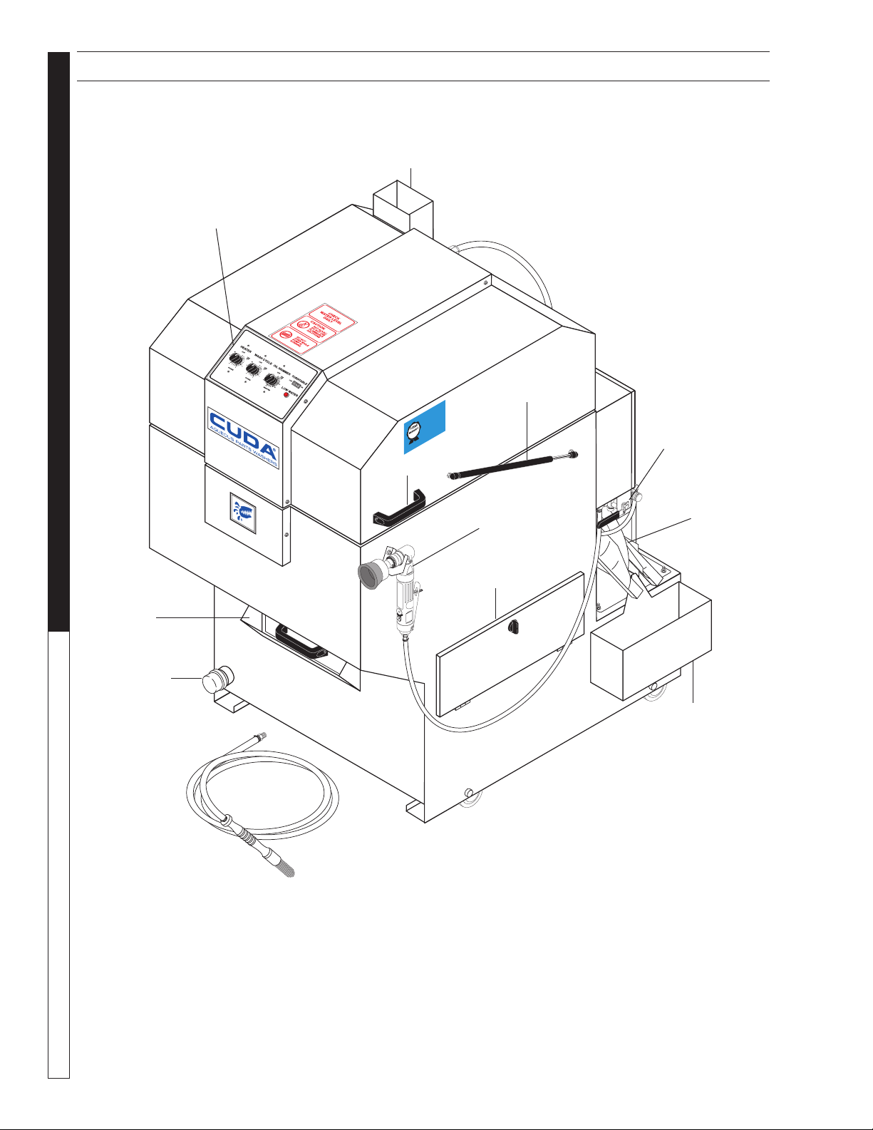
This automatic parts washer is designed to operate
safely and efficiently with a minimum of required mainte-
nance. Before you begin to install and use the machine,
please familiarize yourself with the major components.
WARNING
HIGH PRESSURE
SPRAY CAN PIERCE
SKIN AND TISSUES.
WARNING
PROTECTIVE
EYE WEAR AND
CLOTHING MUST
BE WORN.
WARNING
KEEP WATER SPRAY
AWAY FROM
ELECTRICAL WIRING.
INTRODUCTION

CUDA 2518 • 8.915-630.0 • Rev. 7/13
OPERATOR’S MANUAL
PARTS WASHER
6
89156300-2
9.801-125.0
ATTENTION
USE ONLYCUDA APPROVED
DETERGENTSTO EXTEND
LABORWARRANTY TO 1-YEAR!
MIXDETERGENTS 1 LB (1/2 KG) PER
5-GALLONS(15 LITERS) OF WATER
For CUDAApproved Detergents visit
http://www.cudausa.comor
call 888-319-0882
9.807-513.0
90-DAYLABOR WARRANTY
EXTENDSTO 1-YEAR
WITHEXCLUSIVE USE OF
CUDADETERGENTS
LIMITED
COMPONENT IDENTIFICATION - FRONT
Steam Vent
Control
Panel
Sump
Drain
Debris
Tray
Detail Brush
Assembly
(Optional)
Power Brush
(Optional)
Access
Panel
Lid Support
Strut
Lid Handle
3 Way Air Valve
(Optional)
Oil
Skimmer
Assy.
Oil
Collection
Container

CUDA 2518 • 8.915-630.0 • Rev. 7/13
7
PARTS WASHER OPERATOR’S MANUAL
COMPONENT IDENTIFICATION - REAR
OPERATING INSTRUCTIONS
MAINTENANCE INSTRUCTIONS
CHECK
WATER LEVEL
DAILY
CAUTION
HOT ALKALI
DO NOT USE
FLAMMABLE
SOLUTIONS
DO NOT
OPEN WHILE
PUMP IS
RUNNING
DANGER
HIGH VOLTAGE
WARNING
WARNING
89156300-3
Heating
Element/
Thermostat
Assy.
Power
Cord
Optional
Autofill
Assy. Drive Motor
Assy.
Electrical
Box
Low Water
Shutoff
Sump
Pump
Access Panel
Steam
Vent
Control Panel

CUDA 2518 • 8.915-630.0 • Rev. 7/13
OPERATOR’S MANUAL
PARTS WASHER
8
SECTION 2: INSTALLATION
Read and understand this entire section before you
install your machine.
If you have any questions regarding the installation,
please contact your dealer or call a customer service
representative. When contacting customer service
please refer to the machine identification tag inside
the front cover of this manual for detailed machine
specifications.
Location
To prepare to install your new automatic parts washer,
choose an unobstructed, level site that allows conve-
nient access for operators and maintenance person-
nel. Sources for water and electrical power should be
located near the installation site. If your machine is
equipped with the optional power brush and hand detail
brush you must also run a compressed air line to the
installing site.
Electrical Connections
NOTE: All electrical installation tasks must be per-
formed by a licensed, professional electrician to ensure
safe and proper operation.The installation must comply
with the National Electric Code and all applicable state
and local codes.
The machine can only operate on the type of electri-
cal power indicated on the machine identification tag.
Read and understand the machine identification tag
to determine the electrical power requirements before
installing the machine.
Connect a Compressed-Air Line and
Accessories
This step is required for machines equipped with the
optional power brush and hand detail brush. If your
machine does not have these options, skip the follow-
ing procedure.
NOTE: To ensure proper operation and to minimize
the possibility of premature component failure, make
sure the compressed air is supplied at 75 to 90 psi. It
is also recommended that an in-line moisture trap and
an in-line lubricator be installed on the main air supply
line. Refer to the documentation provided with the air
brush for more information.
Step 1:
Remove the power brush from the box, install the wire
brush in the chuck and connect the air hose.
Step 2:
Familiarize yourself with the three-way air flow select
valve (See Figure Below) then install a fitting to accom-
modate a connection to your compressed air supply.
Step 3:
Connect the shop compressed-air line to the ma-
chine.
Step 4:
Connect the hose from the power brush to the air flow
select valve.
Step 5:
Hang the power brush on the bracket mounted along
the right side of the machine.
Fill the Machine With Water
Step 1:
Familiarize yourself with the water level indicator light
on the control panel (See Figure Below).
Incoming Power
Terminal Strip
Ground
Lug
Compressed Air
Connection
To Power
Brush
Air Flow
Adjustment
Knob
To Detail
Brush
Low Water
Indicator

CUDA 2518 • 8.915-630.0 • Rev. 7/13
9
PARTS WASHER OPERATOR’S MANUAL
SECTION 2: INSTALLATION
Step 2:
Open the right sump cover and feed a water hose di-
rectly into the sump chamber
Step 3:
Fill the sump with water. The sump capacity is 50 gal-
lons.
Step 4:
When the low water level indicator light turns off, the
sump is full. Turn off the water.
NOTE: Monitor the water level carefully - do not
overfill the machine. If you overfill the machine, re-
move excess water using a small submersible pump or a
suitable container.The correct water level is two inches
from the top of the access door when the pump is off.
Step 5:
Close the lid.
Step 6:
Turn the heater timer to the 2 hour position. The sump
will reach operating temperature (160°-180°F) in ap-
proximately one hour.
Step 7:
While the sump water is heating, add the appropriate
quantity of factory approved detergent to the wash
chamber. We recommend mixing the detergent with
warm water in a separate bucket/container and then
pouring the dissolved detergent into the sump.
NOTE: Factory approved detergent is the only deter-
gent approved for use with this automatic parts washer.
It is specially formulated with rust inhibitors and anti-
foaming agents to optimize performance and minimize
maintenance. The use of any other detergent during
the warranty period will void the warranty. In addition,
using factory detergents will extend your 90 day labor
warranty to 1 year.
Step 8:
Close the lid.
Step 9:
Turn the wash cycle timer to 2 hours for the first time
and allow the machine to complete the cycle to thor-
oughly dissolve the detergent into the water.
When the machine stops (and after the wash water
reaches operating temperature), it is ready for use. Re-
fer to Operation for complete operating instructions.

CUDA 2518 • 8.915-630.0 • Rev. 7/13
OPERATOR’S MANUAL
PARTS WASHER
10
Main Operating Components
Familiarize yourself with the main operating compo-
nents before operating the machine.
Control Panel
The control panel is located on the front center of the lid
and it contains the controls for the heater, wash cycle,
oil skimmer, turntable and low-water indicator light (See
Figure Below).
HEATER CONTROL
The heater control is a 12-hour timer switch. It controls
the heating element in the sump chamber. The heater
control is thermostatically set at the factory to reach a
high temperature of 180°F. The temperature is adjust-
able using the thermostat (See Section on Thermostat
for Illustration).
WASH CYCLE CONTROL
The wash cycle control is a 60-minute timer switch with
a hold feature. When set between 1 and 60 minutes,
the timer automatically shuts off the pump and turntable
when the wash cycle is complete. When set to hold,
the pump and turntable run continuously until manu-
ally shut off.
OIL SKIMMER CONTROL
The oil skimmer control is a 30-minute timer switch that
controls the automatic oil skimmer system.
TURNTABLE SWITCH
The turntable switch is a simple rocker switch that en-
ables you to disconnect power to the turntable motor.
Set to ON, the turntable rotates during the wash cycle.
Set to OFF, the turntable does not rotate during the
wash cycle.The switch is useful for washing large parts
that would otherwise impede turntable rotation.
LOW WATER INDICATOR
The low water indicator light illuminates if the wash
solution in the sump is low.
SECTION 3: OPERATION
Lid Safety Switch
The lid safety switch is located on the front edge of the
cleaning chamber. This feature ensures that the water
pump and turntable motor do not operate if the lid is
open or unsecured. The safety switch is adjustable.
ADJUSTING THE LID SAFETY SWITCH
To adjust the safety switch, remove the control panel,
adjust the switch and replace the control panel. When
properly adjusted, you should hear a slight ‘click’ as
the lid closes.
Thermostat
The thermostat is located inside the heating element
and thermostat enclosure.The thermostat is factory set
to heat the wash solution to a maximum temperature
of 180°F.
ADJUSTING THE THERMOSTAT
To adjust the thermostat, rotate the adjustment screw
or knob clockwise to increase the temperature, or
counterclockwise to decrease the temperature (See
Figure Below).
Debris Screen
The debris screen is located just below the wash cham-
ber and is accessible from the front of the machine (See
Figure Below). The debris screen continuously filters
debris particles from the cleaning solution to ensure
blockage-free spray nozzle operation and also provides
a safeguard against small parts that might accidentally
be washed through from the cleaning chamber.
Heater
Control
Oil
Skimmer
Control
Turntable
Switch
Low Water
Indicator
Wash Cycle
Control
Increase
Temperature
Decrease
Temperature
Adjustment
Screw

CUDA 2518 • 8.915-630.0 • Rev. 7/13
11
PARTS WASHER OPERATOR’S MANUAL
SECTION 3: OPERATION
The frequency at which you must clean the debris
screen depends on machine usage. In general, you
should clean the screen before operating the machine
each day.
NOTE: Never operate the machine without the debris
screen in place and never remove the screen while the
machine is operating. The screen is specially sized to
filter particles that could clog the spray nozzles or dam-
age the water pump. Operating the machine without
the debris screen in place could cause spray nozzle
clogging, or water pump failure.
Air Flow Valve (Optional)
The air flow valve is located on the right rear corner of
the machine. It is a three-way ball valve that controls
the flow of compressed air to the power brush and the
hand detail brush (See Figure Below).
Power Brush (Optional)
The power brush is located on the right front corner of
the machine (See Figure Below).
NOTE: The power brush is a standard component on
the model H20-2518 Deluxe Edition. It is available as
an option on the base model H20-2518.
USING THE POWER BRUSH
With stiff stainless steel bristles turning at 1800 RPM,
the power brush easily removes carbon deposits, old
gasket material, or other tightly adhered materials from
parts before washing.
To turn on the power brush, position the air flow select
valve appropriately, then push the power brush lever
lock forward with your thumb and squeeze the throttle
lever to control the speed of the brush.
WARNING: Particles dislodged by the power brush
could cause serious injury to your eyes. Always
wear approved eye and hand protection when using
the power brush.
Detail Brush and Flow Regulator
(Optional)
The detail brush is located on the front inside wall
of the wash chamber. The flow regulator is located
on the right rear corner of the machine (See Figure
Below). The detail brush uses a continuous flow of
hot cleaning solution through its nylon bristles to
help you clean delicate or lightly soiled parts. The
flow regulator controls the flow of cleaning solution
through the detail brush.
ADJUSTING THE FLOW
OF CLEANING SOLUTION
The flow of cleaning solution through the detail brush
is pre-set at the factory. If you need to adjust the flow,
pull out the flow regulator knob, then rotate it clockwise
to decrease the flow or counterclockwise to increase
the flow. After adjusting, push the knob back in to lock
it. (See Figure Above)
NOTE: The detail brush is available as an option on the
base model H2O-2518.
Position #1 - Power Brush Position #2 - Detail Brush
Throttle
Lever Lock
Throttle
Lever
Detail Brush
Tank Rear
Wall
Air Valve
Optional
Detail Brush
Assembly
Pump

CUDA 2518 • 8.915-630.0 • Rev. 7/13
OPERATOR’S MANUAL
PARTS WASHER
12
Oil Skimmer System
The oil skimmer system is located on the right rear cor-
ner of the machine (See Figure Below). It automatically
removes oil from the wash solution to prolong its useful
life. Refer to Using the Oil Skimmer section.
SECTION 3: OPERATION
Low Water Shut-Off
The low-water shut-off system (See Figure Below) shuts
down the machine if the wash solution in the sump
chamber drops below a safe level.The system uses two
proximity switches and a float rod mounted near the rear
of the sump chamber to monitor the water level.
NOTE: If your machine is equipped with the optional
automatic water fill feature, the sump will automatically
fill when the water level drops below the lower low water
proximity switch.
Automatic Water Fill
The automatic water fill system automatically maintains
a proper water level in the sump. It is available as an
option on model H2O-2518 machines.
WATER LEVEL OK:
Both switches OPEN, Automatic
Water Fill Valve (if installed) CLOSED,
Heating Element ON.
LOW WATER LEVEL:
Top switch CLOSED, Bottom Switch
CLOSED, Automatic Water Fill Valve (if
installed) OPEN, Heating Element OFF.
SUMP FILLING:
Top switch CLOSED, Bottom Switch
OPEN, Automatic Water Fill Valve (if
installed) OPEN, Heating Element OFF.
Proximity
Switch
Float
Rod
Oil
Skimmer
Disk
Skimmer
Blades
Motor
Housing
Oil Collection
Container

CUDA 2518 • 8.915-630.0 • Rev. 7/13
13
PARTS WASHER OPERATOR’S MANUAL
SECTION 3: OPERATION
The automatic water fill system uses the low-water
shut-off proximity switches to open and close a water
solenoid valve, which automatically maintains a proper
water level in the sump. The figures on the previous
page describe the operation of the automatic water fill
system.
DETERGENTS
AND ADDITIVES
Detergents
Manufacturer's detergents are the only detergents
approved for use with our Automatic Parts washers.
They are specially formulated with rust inhibitors and
anti-foaming agents to optimize performance and
minimize maintenance. The use of any other detergent
during the warranty period will void the warranty.
To monitor the relative concentration of the detergent
in the wash solution, periodically examine the wash
solution in the sump chamber for the following
indicators:
• Rust inside the machine: not enough
detergent
• Excessive foaming: not enough detergent
• Thick, white residue on parts after
washing: too much detergent
To maintain proper detergent concentration under
typical operating conditions, add detergent each month
after cleaning the sump chamber. Follow recommended
detergent quantities. Use pH kit to determine the proper
amount of detergent to use. If you need help interpreting
test results, contact customer service.
Rust Inhibitor Additive
Factory detergents protect the entire inside of your
machine against the degenerative effects of water
evaporation. A rust inhibitor additive actually evaporates
with the water and continuously coats and protects
metal surfaces, even while your machine is sitting idle.
For more information, contact your distributor or call
customer service.
PREPARING THE MACHINE
FOR USE
Before you begin to wash parts, it is important that you
properly prepare the machine. Before you begin to use
the machine each day:
• checkthewaterlevelandaddwatertothesump
tank if necessary;
• heatthewatertooperatingtemperature;
•adddetergentifnecessary;
• verifythatnoneofthespraynozzlesareclogged;
and
• cleanthedebrisscreen.
WASHING PARTS
The following procedure assumes that the heater is on
and the sump water is at operating temperature.
To wash parts, perform the following procedure.
Step 1:
Load large, heavy parts directly onto the turntable. Load
small, light parts in the small parts basket provided
with your machine. Make sure none of the parts extend
beyond the edge of the turntable and make sure large,
light parts (valve covers, for example) are secured to
the turntable.
NOTE: For optimum cleaning performance, provide a
slight clearance between parts to allow adequate flow
of cleaning solution around and between them.
Step 2:
Close the lid.
Step 3:
Set the wash cycle timer to between 1 and 60 minutes
for a timed wash cycle, or set it to Hold for a continu-
ous wash.
Step 4:
When the machine automatically stops (or after you
manually stop the wash cycle), open the lid and wait a
few moments to allow the parts to cool and dry before
removing them. Most parts will flash-dry in seconds.
SHUTTING DOWN
THE MACHINE
To shut down the machine at the end of the day:
• setthewashcycletimertoOFF;
• settheheatertimertoOFF;
• settheoilskimmertoOFF;
• shutoff thecompressed airat thesupply line
(if installed).
WARNING: If the heater is left unattended, the water
could evaporate and the oil and grease in the wash
chamber could catch fire.
For periods of extended shut-down, disconnect all
power to the machine.

CUDA 2518 • 8.915-630.0 • Rev. 7/13
PARTS WASHER Troubleshooting Guide
14
SECTION 4: TROUBLESHOOTING
PROBLEM POSSIBLE CAUSE SOLUTION
POOR
CLEANING
PERFORMANCE
Parts are obstructing each other Check the position of parts on turntable;
position parts to allow flow of cleaning solution
around and between them.
Low water level in sump Check sump water level and add water if
necessary.
Clogged or improperly aligned
spray nozzles
Check the spray nozzles for obstructions and
alignment; clean and align if necessary.
Wash solution is not properly
heated
Check wash solution temperature; temperature
should be between 160° and 180°F
(See “Wash Solution Is Not Heating” Section)
Pump is not operating properly See ""'“““Pump Does Not Operate Properly”
Section
FOAMING Machine operating with cold water Bring water up to correct temperature
Grease, high detergent motor oils,
transmission oil, gear lubes
Do not place oil pan or transmission pan into
machine without pouring oil out of it.
Not enough detergent Add more detergent, check pH level. Use
defoamer.
WHITE
POWDER
ON PARTS
Solution is old Change sump water and recharge with fresh
detergent and vapor corrosion inhibitor.
Water hardness and TDS (totally
dissolved solids)
Use a water softener and/or change your
sump water more frequently.
Large parts can dry before solution
runs off, leaving powdery residue
Turn heat down to approximately 140°.
WASH
SOLUTION
IS NOT
HEATING
Blown fuse Check the electrical panel for a blown fuse.
Thermostat is set incorrectly Check the thermostat setting; set to 180°F.
Line voltage is too low Contact a licensed electrician to verify that the
line voltage is between 208 and 240V.
Excess debris is built up around
heating element
Check for debris build up around the heating
element; clean out if necessary. (See “Clean-
ing Out the Sump” Section).
Failed heat timer Test the heater timer; replace if necessary.
Failed thermostat Test the thermostat; replace if necessary (See
“Thermostat” Section).
Failed heating element Test the heating element; replace if necessary.
WASH
SOLUTION
IS TOO HOT
Thermostat is incorrectly installed Check the thermostat to ensure that it is
correctly installed into the mounting bracket
(See “Thermostat” Section).
Failed thermostat Replace the thermostat (See “Thermostat”
Section).

CUDA 2518 • 8.915-630.0 • Rev. 7/13
15
PARTS WASHER Troubleshooting Guide
SECTION 4: TROUBLESHOOTING
PROBLEM POSSIBLE CAUSE SOLUTION
MACHINE FAILS
TO START WHEN
“WASHING PARTS”
PROCEDURE IS
FOLLOWED
Main power disconnect is off Verify that no service is being performed on
the machine, then turn the main power
disconnect on.
Lid is not closing properly Check the lid closure safety switch; adjust if
necessary.
Failed lid closure safety switch Test the lid closure safety switch; replace if
necessary (See “Adjusting the Lid Safety
Switch”).
Failed washer cycle timer Test the wash cycle timer; replace if necessary
(See “Lid Safety Switch”).
Pump is not operating properly See “Pump Does Not Operate Properly”
section.
TURNTABLE
DOES NOT
OPERATE
PROPERLY
Parts are obstructing turntable
rotation
Check for parts obstructing rotation of the
turntable; rearrange if necessary.
Drive chain is not on the drive
pulley
Check drive chain; realign on drive pulley if
necessary.
Turntable motor compression
springs are not installed
Check the turntable motor compression
springs; install if necessary (See “Turntable
Motor Assembly”).
Blown fuse Check electrical panel for blown fuse; replace if
necessary.
Failed wash cycle timer Test the electrical panel to eliminate the
possibility of a blown fuse then contact a
licensed electrician or a service representative
to test the turntable motor.
PUMP DOES
NOT OPERATE
PROPERLY
Low water level in sump Check sump water level; add water if neces-
sary.
Pump intake is plugged Check pump intake for obstructions; clean out
if necessary.
Pump overload relay is tripped Reset the motor overload relay.
Blown fuse Check electrical panel for a blown fuse;
replace if necessary.
Line voltage is too low Contact a licensed electrician to verify that the
line voltage is between 208 and 240V.
Pump is failed Test the electrical panel to eliminate the
possibility of a blown fuse then contact a
licensed electrician or a customer service
representative to test the pump motor.
OIL SKIMMER DOES
NOT OPERATE
PROPERLY
Blown fuse Check electrical panel for a blown fuse;
replace if necessary.

CUDA 2518 • 8.915-630.0 • Rev. 7/13
PARTS WASHER Troubleshooting Guide
16
PROBLEM POSSIBLE CAUSE SOLUTION
OIL SKIMMER
DOES NOT
OPERATE
PROPERLY
(CONTINUED)
Skimmer blades are too tight Turn on the skimmer motor and observe the con-
tact between the skimmer blades and the skimmer
disk. If the blades skip, bind, or leave a significant
scratch on the disk, they are too tight. To loosen
the blades, gently bend them away from the skim-
mer disk.
Cooling fan on skimmer
motor is jammed
Turn off power to machine, remove skimmer motor
housing, ensure that cooling fan is free of obstruc-
tions.
Failed skimmer timer Test the skimmer timer; replace if necessary (See
“Wash Cycle, Heater, and Skimmer Timers”).
Failed skimmer motor Contact a licensed electrician to test the motor;
replace if necessary.
LID LEAKS Lid closure safety switch is not
adjusted properly
Check the lid closure safety switch; adjust if neces-
sary.
INTERIOR OF
MACHINE IS
RUSTING
Low detergent concentration
or improper detergent usage
Our detergents, when used at proper concentra-
tions of 10 to 12 scoops (20 to 24 cups) per 50
gallons of water, contains adequate rust inhibitors
to prevent rust. Verify that you are using our deter-
gents at the correct concentration.
SECTION 4: TROUBLESHOOTING

CUDA 2518 • 8.915-630.0 • Rev. 7/13
17
PARTS WASHER Troubleshooting Guide
None
TROUBLESHOOTING THE
ELECTRICAL SYSTEM
To troubleshoot the electrical sys-
tem use the following diagrams to
eliminate the possibility of a blown
fuse or a bad connection, then refer
to Testing Individual Components
to determine which component is
causing the problem.
WARNING: Electrical shock
could cause serious injury or
death.
WARNING
KEEP WATER SPRAY
AWAY FROM
ELECTRICAL WIRING.
• Electricaltroubleshootingshouldbeperformed
by qualified personnel only.
• Avoidcontactwithpowerleads,terminalsand
fuses when power is connected.
• Disconnectpowertomachinebeforeremoving
fuses or other electrical components.
SECTION 4: TROUBLESHOOTING
∞
∞
∞
∞
▲ ▲ ▲
▲▲
▲
▲
▲
▲
▲
Power
ON
Power
OFF
Power
OFF
Power
OFF
Power
OFF
Measure Voltage Across
L1, and L2 Terminals on
Junction Box
Electrical Panel is OK,
Check Main Power
Disconnect
Remove Primary Fuses;
Measure the Resistance
of Each
Fuse is Blown; Replace
Blown Fuse
Remove Secondary
Fuse; Measure the
Resistance
Secondary Fuse is
Blown; Replace Fuse
Remove Heater Fuses;
Measure the Resistance
of Each
One of the Heater Fuses
is Blown; Replace the
Blown Fuse
Remove Pump Fuses;
Measure the Resistance
of Each
One of the Pump Fuses
is Blown; Replace the
Blown Fuse
Electrical Panel is
OK, Refer to Testing
Individual Components
208 to 240V
approximately 0 Ohms
Transformer
Ground
Lug
Relays
Pump
Overload
Relay
Timer
Pump
Fuses Heater
Fuses
Terminal
Strip
None

CUDA 2518 • 8.915-630.0 • Rev. 7/13
PARTS WASHER Troubleshooting Guide
18
SECTION 4: TROUBLESHOOTING
TESTING INDIVIDUAL
COMPONENTS
NOTE: The following troubleshooting procedures re-
quire the use of a volt/ohm meter. If you are not familiar
with using a volt/ohm meter do not attempt to perform
the following troubleshooting procedures. If you need
assistance please contact your distributor.
Wash Cycle, Heater and Skimmer Timers
Step 1:
Disconnect power to the machine
Step 2:
Remove the timer from the control panel and discon-
nect all wires.
Step 3:
With the timer in the OFF position, test for continuity
using the ohm meter.
If there is continuity the timer is no longer functional;
replace the timer.
Step 4:
With the timer in the ON position, test for continuity
using an ohm meter.
If there is not continuity the timer is no longer functional;
replace the timer.
Lid Safety Switch
Step 1:
Disconnect power to the machine.
Step 2:
Remove the switch from the control panel and discon-
nect all wires.
Step 3:
With the switch fully open (not depressed), test for
continuity.
If there is continuity the switch is no longer functional;
replace the switch.
Step 4:
With the switch fully closed (depressed), test for con-
tinuity.
If there is not continuity the switch is no longer func-
tional; replace the switch.
Heating Element
Step 1:
Disconnect power to machine.
Step 2:
Remove the cover from the heating element and ther-
mostat enclosure (Two 5/16" screws).
Step 3:
Detach the two power leads from the heating element
(See Figure Below).
Step 4:
Use an ohm meter to measure the resistance of the
heating element. The resistance should be approxi-
mately 10 ohms; if not, replace the heating element.
Thermostat
Step 1:
Disconnect power to the machine.
Step 2:
Remove the cover from the heating element and ther-
mostat enclosure (Two 5/16” Screws).
Step 3:
Detach the two power leads from the thermostat (See
Previous Figure).
Lid Safety
Switch
Heating
Element
Power
Leads

CUDA 2518 • 8.915-630.0 • Rev. 7/13
19
PARTS WASHER Troubleshooting Guide
Step 4:
Using a large flat-head screwdriver, pry the thermostat
out of the mounting bracket, then remove it from the
machine (See Figure Below).
Step 5:
Set the thermostat to 120°F, warm it to just above 120°F,
then test for continuity.
If there is continuity the thermostat is no longer
functional; replace the thermostat.
Step 6:
Allow the thermostat to cool to room temperature, then
test for continuity.
If there is not continuity the thermostat is no longer
functional; replace the thermostat.
Start Capacitor
Step 1:
Disconnect power to the machine.
Step 2:
Remove the turntable motor cover (Two 5/16" screws,
See Figure Below).
SECTION 4: TROUBLESHOOTING
Step 3:
Visually inspect the start capacitor (See Figure Be-
low). If it appears swollen or deformed, it is no longer
functional; replace the start capacitor.
Step 4:
If the start capacitor is not visibly failed, remove it from
the motor bracket, disconnect the wires, and test it for
shorts using an ohm meter.
If the ohm meter reads approximately 1 ohm, the
start capacitor is no longer functional; replace the
start capacitor.
Mounting
Bracket
Power
Leads
Start
Capacitor
Screws

CUDA 2518 • 8.915-630.0 • Rev. 7/13
PARTS WASHER Maintenance Guide
20
SECTION 5: MAINTENANCE AND REPAIR
MAINTENANCE AND REPAIR
To ensure optimum performance and trouble free op-
eration, observe the following maintenance schedule
consistently.
Daily Maintenance
• Checkthewaterlevel;addwaterifnecessary.
• Cleanthedebrisscreen.
Weekly Maintenance
• Detergent Concentration Level: Check deter-
gent level weekly to maintain concentration level
which decreases when water is added. The pH
level of this detergent must be in accordance with
the detergent manufacturer's recommendation.
• Removeoilfromthewashsolutionusingtheoil
skimmer system (See Using the Oil Skimmer
System).
• Examine the spray nozzles; clean and align if
necessary (See Cleaning and Aligning the
Spray Nozzles).
• To maintain the integrity of the exterior nish,
wipe down the exterior of the machine using
a spray degreaser and a soft, damp cloth. TO
PREVENT ELECTRICAL COMPONENT FAIL-
URE, DO NOT SPRAY THE MACHINE WITH
WATER.
NOTE:Spray degreaser and a damp cloth will usu-
ally remove all dirt and grime from the machine. For
particularly stubborn soap deposits, use a soft cloth
dampened with warm solution from the wash chamber.
Monthly Maintenance
• Drain and clean out the sump chamber
(See Cleaning out the Sump).
Semi-Annual Maintenance
• Lubricate the pivot on the turntable motor
assembly with machine oil or anti-seize.
Using the Oil Skimmer
The oil skimmer is most effective if used when the clean-
ing solution is cool, and after it has been sitting for at
least thirty minutes. The frequency at which you must
remove the oil from the wash solution will depend on
machine usage. Under typical operating conditions you
can expect to remove the oil once each week.
To remove oil from the cleaning solution, perform the
following procedure:
Step 1:
Allow the machine to sit idle for at least 30 minutes to al-
low the oil to float to the surface of the wash solution.
Step 2:
Ensure that the oil collection container is in place (See
Figure Below), then turn the skimmer switch to the 30-
minute position.
Step 3:
Allow the oil skimmer to operate until it is no longer
extracting oil from the cleaning solution.
Tip: While extracting oil from the cleaning solution,
oil will flow off the wiper blades in a fine continuous
stream. Water will flow off the blades in droplets. Once
droplets begin to flow off of the wiper blades, stop the
skimmer motor.
Step 4:
When the skimmer motor stops, dispose of the oil in the
collection container in accordance with local, state and
federal regulations, then replace the container.
Cleaning and Aligning the Spray Nozzles
To ensure optimum cleaning performance, it is important
that you examine the spray nozzles periodically and
clean and align them if necessary.
To clean a plugged nozzle, remove it from the spray pipe
and use a small wire brush to free the nozzle of any
obstructions.When you replace the nozzle on the spray
pipe, make sure you align it according to the following
diagram to maintain a proper spray pattern.
Skimmer
Motor
Wiper
Blades
Skimmer
Disc
Optional Oil
Container
Other manuals for 1.043-342.0
1
This manual suits for next models
5
Table of contents
Other CUDA Washer manuals