4/CULLIGAN ESTATE®2/2MWATERCONDITIONER
Preparation
COMPONENTDESCRIPTION
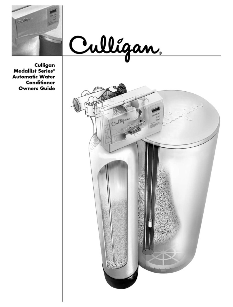
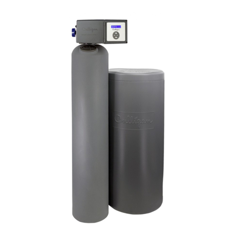
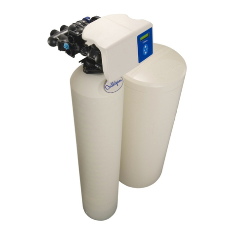
The water conditioner is shipped from the factory in three
cartons. Remove all components from their cartons and
inspect them before starting installation.
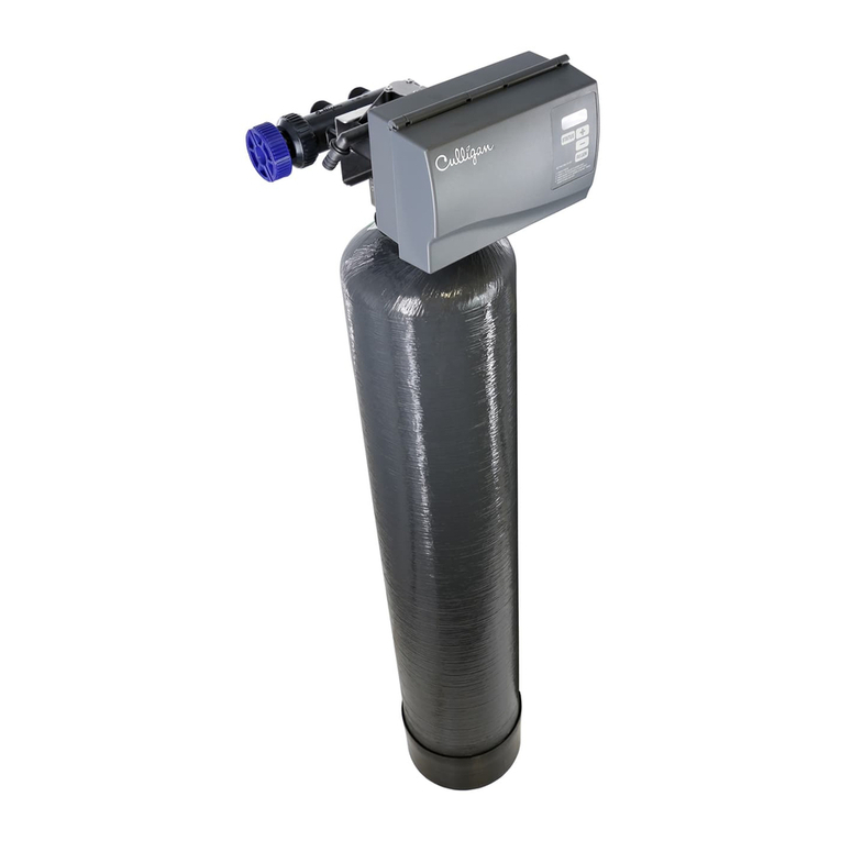
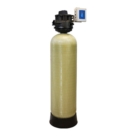
Control Valve Assembly — Includes the 5-cycle regenera-
tioncontrolvalve andelectronic timer assembly.Asmall parts
package contains installation hardware and consumer
literature, including an Owner's Guide and warranty policy.
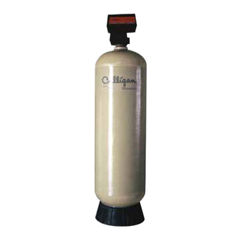
MediaTank—Containsthemediatankcomplete withCullex®
ion exchange resin, underbedding and outlet manifold.
Salt Storage Tank Assembly — Includes salt storage
container with support plate and Dubl-Safe™brine refillvalve
and chamber.
TOOLSAND MATERIALS
The following tools and supplies will be needed, depending
on installation method. Observe all applicable codes.
All Installations
• Safety glasses
• Phillipsscrewdrivers,small and mediumtip
• Gaugeassembly (PN 00-3044-50or equivalent)
• Silicone lubricant (PN 00-4715-07 or equivalent) - DO
NOTUSEPETROLEUM-BASEDLUBRICANTS
• A bucket, preferably light-colored
• Towels
Special Tools
• Torch, solder and flux for sweat copper connections
• Threading tools, pipe wrenches and thread sealer for
threaded connections.
• Saw, solvent and cement for plastic pipe connections.
Materials
• Brineline, 5/16"(PN 00-3031-28or equivalent)
• Drain line, 1/2" (PN 00-3030-82, gray, semi-flexible; or
PN00-3319-46, black,semi-rigid; orequivalent)
• Thread sealing tape
• Pressurereducingvalve (ifpressure exceeds 125psi [860
kPa],PN 00-4909-00or equivalent)
• Pipe and fittings suited to the type of installation
• Water softener salt (rock, solar or pellet salt formulated
specifically for water softeners)
BYPASS
A bypass valve is included with the control valve assembly.
APPLICATION
Waterquality— Verify that raw water hardness and iron are
within limits. Note the hardness for setting the salt dosage
and recharge frequency.
Pressure — If pressure exceeds 125 psi (860 kPa), install a
pressure reducing valve (see materials checklist). On private
water systems, make sure the minimum pressure (the pres-
sureatwhich thepumpstarts) isgreater than 20psi (140 kPa).
Adjust the pressure switch if necessary.
CAUTION:The use of a pressure reducing valve
may limit the flow of water in the household.
Temperature— Do not install the unit where it might freeze,
or next to a water heater or furnace or in direct sunlight.
LOCATION
Spacerequirements —Allow6-12inches(15-30cm)behind
the unit for plumbing and drain lines and 4 feet (1.3 metres)
above for service access and filling the salt container.
Floorsurface— Choosean areawithsolid, levelfloor freeof
bumps or irregularities. Bumps, cracks, stones and other
irregularities can cause the salt storage tank bottom to crack
when filled with salt and water.
Drainfacilities— Choose a nearby drain that can handle the
rated drain flow (floor drain, sink or stand pipe). Refer to the
Drain Line Chart, Table 1 (page 7), for maximum drain line
length.
NOTICE:Most codesrequireananti-siphondevice orairgap.
Electrical facilities — A 6-foot grounded cord is provided.
The customer should provide a 3-prong grounded receptacle,
preferably one not controlled by a switch that can be turned
off accidentally. Observe local electrical codes.
WARNING: ELECTRICAL SHOCK HAZARD! DO
NOT REMOVE THE GROUNDING PRONG! IF THE
RECEPTACLE IS DESIGNED ONLY FOR 2-PRONG
PLUGS,OBTAINA3-PRONGADAPTERANDGROUND
IT SECURELY TO THE RECEPTACLE. DO NOT USE
EXTENSIONCORDS.
