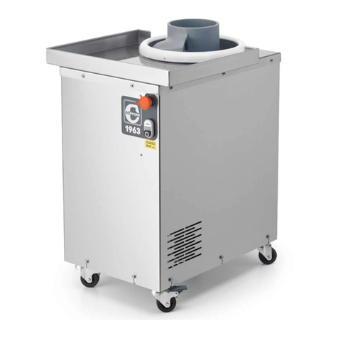
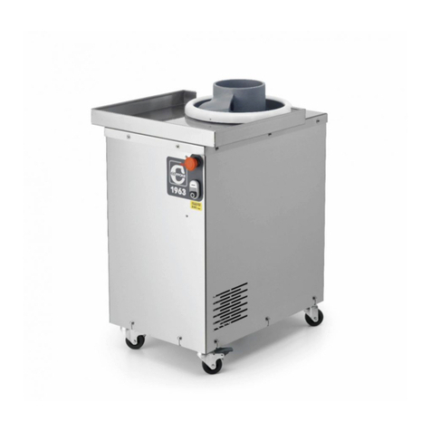
Cuppone LLKBR800 User manual

1
Ed. 0522 - 70702601 REV02 Rounding machine - Preinstallation
LLKBR280
LLKBR800
Dough
Rounder
Pre-installation and installation manual

2
This product has been designed with the utmost care and
has undergone rigorous tests in our laboratories and for this
reason we guarantee its absolute safety and functionality.
The installation must be carried out by professionally qual-
ied staff, that can take responsibility for the installation and
guarantee the best safe operating conditions.
Before the installation, read the content of this manual care-
fully: it contains important information regarding product
assembly and safety regulations.
Technical service
The Dealer can solve any technical problem regarding
installation.
Do not hesitate to contact him in case of doubt.
ContentsIntroduction
1Checks before purchasing...................................................3
2Technical data..............................................................................5
RND280 rounding machine technical data...............................6
RND800 rounding machine technical data...............................6
3INSTALLATION..............................................................................7
Safety instructions.....................................................................................7
Symbols applied to the machine.....................................................8
Transport .........................................................................................................9
Preliminary operations............................................................................9
Positioning .....................................................................................................9
Serial number plate reading ...............................................................10
Electrical connection...............................................................................11
Wiring diagrams..........................................................................................12
4FINAL OPERATIONS..................................................................14
The company cannot be held liable for any print or tran-
scription errors, reserving the right to make changes where
deemed suitable without prior notice.
Partial reproduction without the Manufacturer's consent
is prohibited. Measurements are purely indicative and not
binding.
The original language used to prepare this manual is English:
the Manufacturer is not responsible for any translation/inter-
pretation or print errors.
CUPPONE 1963
Cuppone F.lli S.r.l.
Via Sile, 36
31057 Silea (TV) - ITALY
T +39 0422 361143
F +39 0422 360993
info@cuppone.com - www.cuppone.com

3
Ed. 0522 - 70702601 REV02 Rounding machine - Preinstallation
min.
500 mm
( in. 19,7 )
Max 35°C
Max 70% Min 5°C
Max 104°F
Min 41°C
Fig. 1
Fig. 2
Before purchasing the product and installing it, check the
following conditions, necessary for the correct installation,
operation and maintenance of the product.
A Transport (Owner’s inspection)
√Make sure that, on the day when you receive the prod-
uct or it is installed:
•Fig. 1 lifting equipment is available that can handle
the appliance safely (check weight and dimensions in
the following pages), together with staff qualified to
carry out this operation;
•personal protection equipment is available (e.g. safety
shoes, gloves, etc.)
B Installation room (Owner’s inspection)
√Make sure that:
•the floor of the installation room is fireproof, perfectly
flat and capable of withstanding the weight of the
appliance;
•Fig. 2 the installation room:
• is dedicated and suitable to cooking food;
• has adequate air ventilation;
•complies with the current regulations on health
and safety and systems in the workplace;
• is protected from the weather;
•has a maximum temperature of between +5° (41°F)
and +35°C (104°F);
• has a maximum humidity of 70%.
• the appliance easily passes through doorways;
•Fig. 2 there are NO other sources of heat (i.e. grills,
fryers, etc.), highly flammable substances or fuels
(i.e. gasoline, petrol, bottles of alcohol, etc...) in the
vicinity of the appliance. It is absolutely necessary to
comply with the minimum safety distances between
the product and other flammable equipment or
materials.
•there is adequate ventilation according to the reg-
ulations in force in the Country of installation. If this is
not the case, a ø140 mm [Ø5.51”] air intake is manda-
tory, communicating with the outside or a ventilated
room (i.e. storeroom, attic, garage, basement).
Leave a free space of at least 20 cm between the appliance
and the walls of the room and/or other equipment to facili-
tate the use, cleaning and maintenance of the machine itself.
When choosing the positioning room, take into ac-
count that the appliance must be easy to move for
any extraordinary maintenance: be careful since any
brickwork after installation (e.g.: wall construction, door re-
placement with narrower ones, renovations, etc.) do not
hamper movements.
1CHECKS BEFORE PURCHASING

4
DElectrical connection (qualied electrician’s
inspection)
√For a correct connection during the installation:
•provide a socket connecting to the electrical net-
work near the product.
• single-phase machines have the connection cable
and plug already tted;
•three-phase machines have the power cable
already installed; a plug (not supplied) must be
tted to it of suitable capacity. This operation must
be carried out by qualified personnel.
•check that the systems in the room comply with
the legal provisions in force in the country of
use and meet the specifications on the serial number
plate. For a correct electrical connection, the appli-
ance must:
•be included in an equipotential system in
compliance with the legislation in force. This
connection must be made between the various
devices with the terminal marked with the equi-
potential symbol . The cable must have a
maximum cross-section of 10 mm2(in compliance
with IEC EN 60335-2-42:2003-09) and must be
yellow-green;
•must be grounded to the mains (green-yel-
low wire);
•must be connected to a thermal dierential
switch in compliance with the regulations in force
(0.03A A type);
•must be connected to an omnipolar circuit
breaker allowing complete disconnection in
overvoltage III category conditions.
Electrical data
Model Supply
VMotor
kW
Current
draw
A
Cable type
n x mm2
LLKBR280 AC 230V/50Hz 0.37 kW 2.7 3x1.5
AC 3 N 400V/50Hz 0.37 kW 1.8 4x1.5
LLKBR800 AC 230V/50Hz 0.37 kW 2.7 3x1.5
AC 3 N 400V/50Hz 0.37 kW 1.8 4x1.5
Checks before purchasing

5
Ed. 0522 - 70702601 REV02 Rounding machine - Preinstallation
2
1
3
4
5
6
7
STOP
Fig. 3
2TECHNICAL DATA
Knowing the appliance
This appliance has been designed and built for food use
only, for the cold processing of cereal flour-based doughs; its
main use is therefore in pizzerias, bakeries and pastry shops.
The purpose of the machine is to round portions of already
portioned dough to the desired weight, while maintaining the
basic characteristics of the dough unaltered; the action carried
out by the screw determines the advancement of the dough
and the consequent compression of the same against the
ribbed surface of the cylinder from which, once it comes out,
it will be very compact and with good roundness.
Fig. 3
The main parts of the machine are:
1 Auger
2 Tray: accommodates the rounded dough balls
3 Cylinder
4 Emergency STOP button
Pressing the red STOP button switches off the machine
and stops the rotary movement of the cylinder.
It must therefore be used only when really necessary and
not as an ON/OFF switch to be used at the end of the work
day.
If pressed, to restore the conditions of use, unlock the
button by turning it clockwise.
5 Control panel - ON/OFF keys
- black button 0: machine stop
- white button I: machine start
- central light: if on, it indicates that the machine is on.
6 Wheel with brake: during normal use, always keep the
appliance blocked by lowering the brakes of the front
wheels.
7 Wheel without brake

6
565
390
795
710
555
440
390
745
625
410
830
725
610
505
435
775
BR280 rounding machine technical data
rounding machine weight 55 kg [121.2 lb]
weight of packaging + rounding machine 64 kg [141 lb]
rounding machine packaging measurements 500 x 750 x 1000 mm
[19.69 x 29.53 x 39.37”]
Dough size
minimum maximum
20 g [0.044 lb / 0.70 ounces] 300 gr [0.66 lb / 10.58 ounces] Dough size
minimum maximum
20 g [0.044 lb / 0.70 ounces] 900 gr [1.9 lb / 31.7 ounces]
rounding machine weight 86 kg [189.5 lb]
weight of packaging + rounding machine 95 kg [209.4 lb]
rounding machine packaging measurements 500 x 750 x 1000 mm
[19.69 x 29.53 x 39.37”]
BR800 rounding machine technical data

7
Ed. 0522 - 70702601 REV02 Rounding machine - Preinstallation
Safety instructions
•Read this guide carefully before installing the
appliance, and keep it with care in an accessible
place for any future consultation by the various
operators.
•Moreover, the manual must always accompany
the product through its life, even in case of
transfer.
•Before any movement or installation, check
that the room is suitable and systems comply
with the installation country standards and the
specifications indicated on the appliance rating
plate.
•All installation, assembly and non-routine
maintenance operations must be performed
exclusively by qualified technicians that are
authorised by the Manufacturer, in compliance
with the regulations in force in the user country,
and with the regulations on systems and work
safety.
•Before performing any installation or mainte-
nance, disconnect the electricity supply.
•Unauthorised actions, tampering or modifica-
tions that do not follow the information provid-
ed in this manual can cause damages, injuries or
fatal accidents and null and void the warranty.
•It is forbidden to install the product in environ-
ments at risk of explosion.
•Installation or maintenance that fails to comply
with the instructions in this manual may cause
damage, injury or fatal accidents.
•Do not obstruct the ventilation system of the
room in which this equipment is installed.
Do not obstruct the ventilation and exhaust
holes of this or other equipment.
•Persons not involved with the appliance installa-
tion may not pass through or stand in the work
area during appliance assembly.
•The serial plate provides important technical
information. This is vital in case of a request for
maintenance or repair of the equipment: please
do not remove, damage or modify it.
•These appliances are intended to be used for
commercial applications, for example in res-
taurant kitchens, canteens, hospitals and com-
mercial companies such as bakeries, butcher
shops, etc., but not for the continuous and mass
production of food.
•To avoid risks, if the power cable is damaged,
it must be replaced by the Retailer, its service
agent or qualified personnel.
•Failure to follow these regulations may cause
damage or even fatal injury, subsequently
invalidating the guarantee and relieving the
Manufacturer of all liability.
3INSTALLATION
Symbols used in the manual and on
the labels applied to the machine
Indicates that caution is required when performing
an operation described in a paragraph that bears
this symbol. The symbol also indicates that max-
imum operator awareness is required in order to
avoid unwanted or dangerous consequences
Reference to another chapter where the subject is
dealt with in more detail.
Manufacturer’s tip
Dangerous voltage
The symbol identifies the terminals which, connect-
ed to each other, carry the various parts of a device
or system to the same potential (not necessarily the
earth potential)
Indicates that it is necessary to read carefully the
paragraph marked with this symbol before installing,
using and maintaining the equipment
The company cannot be held liable for any print or tran-
scription errors, reserving the right to make changes where
deemed suitable without prior notice.
Partial reproduction without the Manufacturer's consent
is prohibited. Measurements are purely indicative and not
binding.
The original language used to prepare this manual is English:
the Manufacturer is not responsible for any translation/inter-
pretation or print errors.

8
Installation
Symbols applied to the machine
Main regulations and directives complied with and to be complied with
Directive 2014/35/EU“Concerning the approximation of the laws of the Member States relating to electrical equipment
intended for use within certain voltage limits”.
• Directive 2004/108/EC“Concerning the approximation of the laws of the Member States relating to electromagnetic
compatibility and repealing Directive 89/336/EEC”.
• Directive 89/391/EEC“Concerning the implementation of measures aimed at promoting the improvement of the
health and safety of workers in the workplace”.
• Directive 2006/42/EC“Relating to machinery and amending directive 95/16/EC”.
• Directive 85/374/EEC and Directive 1999/34/EC“Concerning the approximation of the laws, regulations and
administrative provisions of the Member States regarding liability for damage from defective products”.
Attention, moving mechanical parts
Attention, hand crushing risk
It is FORBIDDEN to remove the safety devices
IT IS FORBIDDEN to clean, lubricate and adjust the elements of the
machine when they are moving

9
Ed. 0522 - 70702601 REV02 Rounding machine - Preinstallation
H
2
O
min.
500 mm
( in. 19,7 )
Max 35°C
Max 70% Min 5°C
Max 104°F
Min 41°C
Fig. 4 Fig. 5
Fig. 6
Transport
Fig. 4
Fitted with personal protection equipment, transport the
appliance to the installation location. Use suitable equipment,
capable of dealing with its weight: persons not involved with
the appliance installation may not pass through or stand in the
work area during the appliance assembly. During the transport,
pay particular attention to passing through openings and/or
doors.
Preliminary operations
Fig. 5
Carefully remove the protective film.
If any glue residue is left on the surfaces, remove it with soapy
water but without any corrosive or abrasive products or sharp
or pointed instruments.
Check that all the parts making up the product are in
good condition and without any faults or breakages, if
that is not the case, contact the Dealer for the proce-
dures to follow.
Positioning
Fig. 6
Install the appliance in a room:
• dedicated and suitable to the cooking of food;
• having adequate air ventilation;
• containing no flammable or explosive elements;
•that complies with the current regulations on health and
safety and systems in your country;
• is protected from the weather;
•has a maximum temperature of between +5° (41°F) and
+35°C (95°F);
• has a maximum humidity of 70%.
Leave a free space of at least 20 cm between the appliance and
the walls of the room and/or other equipment to facilitate the
use, cleaning and maintenance of the machine itself.
To reduce the risk of a fire, comply with the stated
minimum distances and install the appliance in re-
proof environments that are not at risk of explosion.
The floor of the installation room must have a surface re-
proof finish too.
Installation

10
MADE IN ITALY
Mod. RND280-A5-CP
VOLT AC KW
2021
S/N RND280A5CP 21010203
VOLT
AC
230V, 50Hz
KW 0,37
Fig. 7
Installation
Model
Electrical parameters
Absorption
Year of production
Serial number
Serial number plate reading
Fig. 7
The serial number is on the back of the appliance.
It provides important technical information that is vital in case
of a request for maintenance or repair of the appliance: please
do not remove, damage or modify it.

11
Ed. 0522 - 70702601 REV02 Rounding machine - Preinstallation
1
2
Fig. 8 Fig. 9
Installation
Electrical connection
Before installing the appliance, check that systems
comply with the regulations in force in the country
where it is going to be used and with the specica-
tions indicated on the appliance rating plate on the LH
side of the product.
• single-phase machines have the connection cable and
the plug already tted; for the connection, just insert the
plug in a socket of suitable capacity Fig. 8
•three-phase machines have the power cable already
installed; a plug (not supplied) must be tted to it of
suitable capacity. This operation must be carried out by
qualified personnel.
For a correct electrical connection, the appliance must:
•be included in an equipotential system Fig. 9 in com-
pliance with the legislation in force. This connection must be
made between the various devices with the terminal marked
with the equipotential symbol . The cable must have a
maximum cross-section of 10 mm2(in compliance with
IEC EN 60335-2-42:2003-09) and must be yellow-green;
• must be grounded to the mains (green-yellow wire);
•must be connected to a circuit breaker in compliance with
the regulations in force (0.03A A type);
•must be connected to an omnipolar circuit breaker
allowing complete disconnection in overvoltage III category
conditions.
The Manufacturer accepts no liability for failure to comply with
the above.
Installation
The following pages show the electrical diagrams:
please refer to the one of the specific model to
connect.
If required, the cable must be replaced by the Dealer or its technical service or by a person with similar qualifications to
prevent any risk.
Electrical data
Model Supply
VMotor
kW
Current
draw
A
Cable type
n x mm2
LLKBR280 AC 230V/50Hz 0.37 kW 2.7 3x1.5
AC 3 N 400V/50Hz 0.37 kW 1.8 4x1.5
LLKBR800 AC 230V/50Hz 0.37 kW 2.7 3x1.5
AC 3 N 400V/50Hz 0.37 kW 1.8 4x1.5

12
AC 230V/50Hz
Wiring diagrams
Abbreviation Description
D1 Semiconductor diode
K1 Power relay
LED1 Light emitting diode
R1 Resistor
S1 NC limit switch
START NO control or button
STOP NC control or button
T1 Transformer
FC Limit switch faston terminal

13
Ed. 0522 - 70702601 REV02 Rounding machine - Preinstallation
AC 3 N 400V/50Hz
0,37 kW
Wiring diagrams
Abbreviation Description
KM1 Power relay
M Motor
SQ NC emergency limit switch
PA NC stop button
PM NO start/stop button
T1 Transformer
H1 Bulb

14
Pre-testing and nal inspection
The product is checked and tested in the Manufacturer’s plant before being delivered to the customer.
The “production process check sheet” enclosed with it guarantees that each step in the production process, from assembly to packaging, was carefully checked from both the operating and
safety standpoints.
After installing the appliance, to complete the installation, carry out A, Band C.
AChecking the installation is correct
Mark with a “√“ all the boxes of the table below: this will confirm the installation is complete and correct.
√ Positioning checks
Is the installation room adequate and compliant with regulations? (minimum, maximum temperature, etc.)
Is the appliance resting on a perfectly level floor?
Have the minimum distances stated been complied with?
Has the protective film been removed from the surfaces?
√ Electrical checks
Does the mains voltage match the data on the rating plate?
Do electric connections meet current regulations in the country of installation and follow the diagrams supplied?
√ Miscellaneous
Does the user have all the documentation relative to the product?
BChecking the operation and rst start-up
Start the appliance following the instructions in the“Use and Maintenance”manual annexed: monitor it during the whole test and check that all the electrical components work properly.
CWarranty activation
At the end of the test, the warranty MUST be activated.
IF NOT REGULARLY ACTIVATED, THE VALIDITY OF THE SAME STARTS FROM THE INVOICE DATE AND NOT FROM THE ACTUAL INSTALLATION
DATE.
4FINAL OPERATIONS

15
Ed. 0522 - 70702601 REV02 Rounding machine - Preinstallation
Problems during use
During use, some problems may occur that can be easily solved following the instructions detailed below.
PROBLEM FOUND PROBABLE CAUSES SOLUTIONS FOR THE USER
The dough balls stick to the auger and find it
difficult to get back up The dough is too hydrated Use doughs with hydration from 50 to 65%.
Dough balls do not stick to the auger but
find it difficult to get back up
The dough is not very hydrated Use doughs with hydration from 50 to 65%.
The dough was left in the air for a long time and
dried up Once the dough is portioned, start rolling quickly
The portion of dough that goes into the auger
is too large
Comply with the following instructions:
Model Portion weight Dough hydration
Minimum Maximum
LLKBR280 20 g [0.044 lb / 0.70 ounces] 300 gr [0.66 lb / 10.58 ounces] from 50% to 65%
LLKBR800 20 g [0.044 lb / 0.70 ounces] 900 gr [1.9 lb / 31.7 ounces] from 50% to 65%
The portions of dough were floured before
being inserted into the auger Do not flour the dough portions
The lower disk under the auger
must be cleaned Remove and clean it
The rounded ball is much larger than the
amount of dough inserted
The portions of dough were inserted too quickly
one after the other inside the auger and joined
together
Increase the time between inserting one portion of dough and the next
The surface of the ball formed is not
smooth and has imperfections
The dough did not rest long enough before
portioning Increase the resting time of the dough before portioning it
The dough is too hydrated Use doughs with hydration from 50 to 65% or, alternatively, cool the dough to about 10°C (50°F)
before inserting it into the auger of the rounding machine
The leavening of the dough, made in the refri-
gerator, took place before the balls were formed
(rising/mass leavening).
Use doughs with hydration from 50 to 65%. Leavening in the refrigerator must take place after
forming the balls.
After pressing the ON/OFF button, the ma-
chine does not start
The appliance has been stopped pressing the
emergency button
To reset the normal operating conditions, unlock the emergency button rotating it clockwise
and restart the machine with the ON/OFF button
The machine is not powered Make sure that the plug is correctly inserted into the socket and that there are no interruptions
to the electricity supply (e.g. black-out)
Some component is broken Contact the Dealer

CUPPONE 1963
Cuppone F.lli S.r.l.
Via Sile, 36
31057 Silea (TV) - ITALY
T +39 0422 361143
F +39 0422 360993
LLK
Units 3 - 5 Belgrave Ind Estate,
Honeywell Lane,
Oldham, OL8 2JP
01616335797
www.llkpizzapros.co.uk
This manual suits for next models
1
Table of contents
Other Cuppone Commercial Food Equipment manuals

Cuppone
Cuppone RND280 User manual

Cuppone
Cuppone BERNINI BRN 280 User manual

Cuppone
Cuppone Pizzaform User manual

Cuppone
Cuppone LLKBR280 User manual

Cuppone
Cuppone Pizzaform Series Parts list manual

Cuppone
Cuppone LLKAR20/300 Specification sheet

Cuppone
Cuppone Pizzaform User manual

Cuppone
Cuppone PZF/30 User manual

Cuppone
Cuppone Michelangelo ML 435/1 Operating manual

Cuppone
Cuppone RND280 User manual