manuals.online logo
Brands
  1. Home
  2. •
  3. Brands
  4. •
  5. Current
  6. •
  7. Lighting Equipment
  8. •
  9. Current DualLite DYNHL Series Manual

Current DualLite DYNHL Series Manual

DYNHL Series
High-Lumen LED Industrial Emergency Lighting Unit
Wet Location, NEMA 4X & Food Processing
Standard and Remote Capacity
Installation, Operation, and Service Instructions
All steel, aluminum and thermoplastic parts are recyclable.
NOTICE: Emergency units contain rechargeable batteries which
must be recycled or disposed of properly.
RECYCLING INFORMATION
Maintenance
This emergency lighting unit should be tested and maintained in accordance with National Electrical Code and NFPA 101 Life Safety
Code requirements. It is recommended that emergency light fixtures be tested for 30 seconds once a month and for 90 minutes once a
year.
Taking AUnit Out Of Service
If a unit is to be deliberatelytaken out of service for an extended period, the battery lead connector should be disconnected from the
charger circuit board and insulated so that the battery will go into storage in a fully charged condition.
Replacing The Battery
1. De-energize the AC power.
2. Remove the cover.
3. Disengage the battery harness from the charger PCB harness.
4. Disconnect the battery strap and remove battery pack.
5. Replace with new battery (see unit model label or battery label for correct p/n)
and repeat steps above in reverse.
Replacing LED Lamps
The LED lamps inside the unit are not replaceable or field serviceable. Please see dual-lite.com for further assistance.
Troubleshooting
Emergency circuit does not work
• Batteries are shipped uncharged and disconnected. Connect battery leads and charge 24 hours before testing.
• Make sure the charger board and test button/light pipe are properly seated and aligned.
• Check wiring connections
OPERATION
IMPORTANT SAFEGUARDS
When using electrical equipment, basic safety precautions should always be followed
including the following.
READ AND FOLLOWALL SAFETY
INSTRUCTIONS
Do not let power supply cords touch hot surfaces.
Do not mount near gas or electric heaters.
Equipment should be mounted in locations and at heights where it will not readily be
subject to tampering by unauthorized personnel.
The use of accessory equipment not authorized by the manufacturer may cause an
unsafe condition.
Do not use this equipment for other than its intended purpose.
Servicing of this equipment should be performed by qualified service personnel.
Test cycling: the Life Safety Code (NFPA 101) requires testing of emergency lighting
units once a month for a minimum of 30 seconds, and once a year for a minimum of
90 minutes.
INSTALLER:
•
SEE UNIT LABEL FOR ADDITIONAL MODEL SPECIFICATIONS
•SAVE THESE INSTRUCTIONS FOR USE BY OWNER/OCCUPANT
1.
2.
3.
4.
5.
6.
7.
This equipment has been tested and found to comply with the limits for a Class A digital device, pursuant to
part 15 of the FCC Rules. These limits are designed to provide reasonable protection against harmful
interference when the equipment is operated in a commercial environment. This equipment generates, uses,
and can radiate radio frequency energy and, if not installed and used in accordance with the instruction
manual, may cause harmful interference to radio communications. Operation of this equipment in a
residential area is likely to cause harmful interference in which case the user will be required to correct the
interference at his own expense.
Service/Maintenance
Automatic Tests
The unit will automatically initiate a self-test/
self-diagnostic cycle based on the following table:
Manual Tests
By using the unit's test switch or laser pointer, one
can initiate different duration test cycles based on
the following table:
Pressing test switch or flashing laser sensor at any time after a 90 minute test cycle has begun cancels the
remainder of the 90 minute test and returns the unit to normal operation. See page 3 for laser pointer test
details.
WARNING- This product containschemicals known to the State of Califorina to cause cancer, birth
defects, and/or other reproductive harm. Thoroughly wash hands after installing, cleaning, or otherwire
touching this product.
currentlighting.com/dual-lite
© 2022 HLI Solutions, Inc. All rights reserved. Information and specifications subject to
change ithout notice. All values are design or typical values hen measured under
laboratory conditions.
Rev 10/10/22
93157888_D
Initiating Action Test Cycle
Press test switch/flash sensor once 1 minute
Press test switch/flash sensor twice 90 minutes
Testing Period Duration of Test
Once a month 1 minute
Once every 6 months
Alternating: 30 minutes
or 90 minutes
FIXTURE INSTALLATION
Wall, Ceiling or Pole Mounting
1. The DYNHL mounting plate can be mounted directly to a wall, ceiling
or
pole (using appropriate hardware). If “J-box” mounted and the plastic
housing back K.O. is removed the unit is not considered water proof.
2. Once mounting plate is secured, you can hang the DYNHL Industrial
Unit
and add security screws (qty 4).
3. If the DYNHL unit is mounted to the ceiling the 4 security screws are to
be added to keep the unit secure to the mounting plate.
4. If “J-box” mounted & wired thru box, ground DYNHL mounting plate
with
green ground wire & green hex head screw (provided).
5. For all units wired using conduit, use 1 of the 3 conduit (K.O.)
mounting locations.
6. Only use UL Listed water tight conduit fittings that meet the
requirements of the UL 514B Standard for Conduit Tubing and Cable
Fittings when using (K.O.’s see note 5).
7. Connect wire from the unit to the building leads and secure with
wire nuts.
8. For remote capable DYNHL models, cut ORANGE wire connector from
orange remote leads and strip ½ inch for both lead ends. Observe
proper polarity when connecting remote leads to remote fixtures.
Pos. (+) to red remote fixture lead and Neg. (-) to black remote
fixture lead.
9. Connect battery pack harness to PCB charger harness.
10. For pole mounting used additional #8-32 x ¼ long screws (qty 2) and
both toothed mounting brackets as shown. Banding straps are not
provided due to varying pole and column dimensions.
OPERATION
Lamp Head Adjustment
1. Loosen the three captive screws on the Food Processing clear cover.
2. Remove cover (all models without clear cover skip step 1 & 2).
3. Loosen set screws 2 per head and adjust axially on stem.
4.
Rotate lamp heads to desired position.
5. Lock set screws once desired position is set (hex wrench provided).
6. Reverse steps 2&1 (if required).
OPERATION
***Once remote capacity basemodels DYNHL12I-4X or DYNHL12I-4X-FP have been installed press and
hold the test button for more than 5 seconds to initiate the “LOAD LEARN” process.***
DYNHL Wiring Diagram
“AC ON” LED is illuminated green when AC power is present.
NOTE: All models are supplied with an AC Lockout circuit, which prevents the emergency lights from
illuminating when the battery is connected and no AC power is present.
NOTE: All models are supplied with Low Voltage Disconnect circuit, which prevents damage to the battery
from deep discharge during prolonged emergency operation.
NOTE: Batteries are often shipped in a discharged state – this is normal. The battery will require charging.
Allow 24 hours of charging before testing the unit.
Models are equipped with SPECTRON®
Self-Testing/Self-Diagnostic Circuitry and provide:
• Visual indication of AC power status
• Visual indication on self-diagnostic status and results
Visual indication of any unit malfunctions include –
• Battery Disconnected
• Battery Fault
• Charger Fault
• LED Driver Fault
• Lamp Fault
• Load Learn Failure
SPECTRON® also includes:
Browout protection: Unit will automatically transfer to emergency
operation upon detection of low AC power
(approximately 80% of nominal line.)
Time Delay Retransfer: upon return of normal AC power, unit will
remain in emergency mode for an additional
15 minutes to allow AC power to stabilize.
Unit can be hung by threaded rod (3/8" rod is
recommended).
Use appropiate hardware to support this unit when
threaded rod mounted. Lock tight glue is
recommended for all mounting hardware.
DRILL "W" (.397
O
)
MTG PLATE HOLES
8X 5/16 DIA.
8X BANDING
STRAP SLOT
1" X 1/4"
TYPICAL BANDING
STRAPS (NOT PROVIDED)
Pole Mounting
4
2
3
1
5
1
10
7
6
5
6
7
8
9
BLK (NEG -) RED (POS +)
RED (POS +)
BLK (NEG -)
RIBBON
CABLE
J6 J10 J5
J9 AC2 AC1
AC INPUT
BLK (HOT)
WHT (COM)
ORG (NEG -)
ORG (POS +)
ORG
WIRE
CONN.
REMOTE
LEAD (+) REMOTE
LEAD (-)
93055896
93061887
93159164
93055897
93055812
NOTE: IF UNIT IS IN A WET LOCATION
ENVIORNMENT, ALL COVER SCREWS
ARE TO BE TORQUED TO 5-6 IN-LBS
OR UNTIL COVER SEATS WITH
HOUSING
DO NOT OVER TIGHTEN SCREWS (7
PLCS)
2
1
2
Units are equipped with a laser activated testing feature which allows test initiation with a laser pointer (sold separately).
- For a 1 minute test, aim laser beam onto area shown until the unit’s lamp heads turn on and the green LED Status
Indicator starts blinking twice every second. The unit will stay in this mode for the complete duration of the test.
- To change from a 1 minute test to a 90 minute test, aim laser onto area shown again until the green LED Status
Indicator starts blinking at a slower pace, once every second. The unit will stay in this mode for the complete duration of
the test.
- To cancel test cycle, aim laser onto area shown while the 90 minute test is in progress until the unit’s lamp heads turn
off and LED Status Indicator stops blinking and comes back to a solid green.
NOTE:
Maintain a steady beam onto area shown.
TEST BUTTON
93159180
93159181
Laser Activated Testing
93159182
LASER TEST
SENSOR
Other Current Lighting Equipment manuals

Current Orbit Marine IC PRO LED Installation instructions

Current

Current Orbit Marine IC PRO LED Installation instructions

Current Arize Element L1000 Gen2 User manual

Current

Current Arize Element L1000 Gen2 User manual

Current HCX Series User manual

Current

Current HCX Series User manual

Current GEPS24-180U User manual

Current

Current GEPS24-180U User manual

Current Dual-Lite PLD9-2H Manual

Current

Current Dual-Lite PLD9-2H Manual

Current Evolve GEH6083 User manual

Current

Current Evolve GEH6083 User manual

Current Evolve EFHH Series User manual

Current

Current Evolve EFHH Series User manual

Current Dual-Lite PLD10 Manual

Current

Current Dual-Lite PLD10 Manual

Current 95W REEF LED Mini LOOP User manual

Current

Current 95W REEF LED Mini LOOP User manual

Current EVOLVE EAL Series User manual

Current

Current EVOLVE EAL Series User manual

Current REEF R24 User manual

Current

Current REEF R24 User manual

Current GTX TRAF324 User manual

Current

Current GTX TRAF324 User manual

Current GTX PS7-CFF1-46A-J User manual

Current

Current GTX PS7-CFF1-46A-J User manual

Current Single TrueLumen PRO User manual

Current

Current Single TrueLumen PRO User manual

Current DUAL LITE EVHC Series User manual

Current

Current DUAL LITE EVHC Series User manual

Current FLOOD Series User manual

Current

Current FLOOD Series User manual

Current Lumination Tetra AL10 Series User manual

Current

Current Lumination Tetra AL10 Series User manual

Current Tetra GERLB2465 User manual

Current

Current Tetra GERLB2465 User manual

Current Arize Factor User manual

Current

Current Arize Factor User manual

Current Tetra GEXNBL-1 User manual

Current

Current Tetra GEXNBL-1 User manual

Current ColorPLUS+ 9050 User manual

Current

Current ColorPLUS+ 9050 User manual

Current Dual-Lite PLD7 Manual

Current

Current Dual-Lite PLD7 Manual

Popular Lighting Equipment manuals by other brands

MC Crypt DL-1101 instruction manual

MC Crypt

MC Crypt DL-1101 instruction manual

HQ Power VDPL192UV user manual

HQ Power

HQ Power VDPL192UV user manual

MegaLite Drama Strip P840 user manual

MegaLite

MegaLite Drama Strip P840 user manual

PULSE+ STAGEPAR-108 user manual

PULSE+

PULSE+ STAGEPAR-108 user manual

HQ Power SEISMO 250 manual

HQ Power

HQ Power SEISMO 250 manual

LIVARNO LUX Z31094A Assembly, operating and safety instructions

LIVARNO LUX

LIVARNO LUX Z31094A Assembly, operating and safety instructions

IMG STAGE LINE LSX-40G instruction manual

IMG STAGE LINE

IMG STAGE LINE LSX-40G instruction manual

HAMPTON BAY Windsor 336-610 instruction manual

HAMPTON BAY

HAMPTON BAY Windsor 336-610 instruction manual

North Light XYIP-5ELED-300B10-2 instruction manual

North Light

North Light XYIP-5ELED-300B10-2 instruction manual

Unibright LaVilla48 LVTPSBW installation manual

Unibright

Unibright LaVilla48 LVTPSBW installation manual

JB Systems Light GALAXY LED - V1.0 Operation manual

JB Systems Light

JB Systems Light GALAXY LED - V1.0 Operation manual

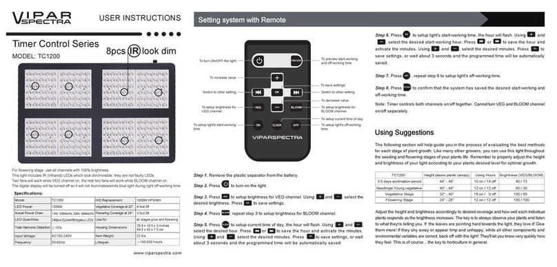
viparspectra Timer Control TC1200 User instructions

viparspectra

viparspectra Timer Control TC1200 User instructions

Lightmybricks LEGO 75276 installation guide

Lightmybricks

Lightmybricks LEGO 75276 installation guide

LIVARNO LUX 103126 Operation and safety notes

LIVARNO LUX

LIVARNO LUX 103126 Operation and safety notes

Show Tec Matrix 5x5 Blinder Product guide

Show Tec

Show Tec Matrix 5x5 Blinder Product guide

afx light BARLED18-PIX user manual

afx light

afx light BARLED18-PIX user manual

Claypaky DISPLAY LINE C52116 operating instructions

Claypaky

Claypaky DISPLAY LINE C52116 operating instructions

Show Tec Club Color Wash 250 MKII manual

Show Tec

Show Tec Club Color Wash 250 MKII manual

manuals.online logo
manuals.online logoBrands
  • About & Mission
  • Contact us
  • Privacy Policy
  • Terms and Conditions

Copyright 2025 Manuals.Online. All Rights Reserved.