manuals.online logo
Brands
  1. Home
  2. •
  3. Brands
  4. •
  5. Claypaky
  6. •
  7. Lighting Equipment
  8. •
  9. Claypaky DISPLAY LINE C52116 User manual

Claypaky DISPLAY LINE C52116 User manual

ISTRUZIONI PER L’USO
SUPPORTO PER DIAPOSITIVA FISSA (C52116)
DISPLAY LINE
studio
Rev. 1 11/00 Cod. 099517
ITALIANO
®
Il presente foglio di istruzioni deve essere letto unitamente al manuale di istruzioni fornito
con il proiettore sul quale si intende montare questo accessorio.
Questo accessorio può essere montato sulle guide elettrificate dei proiettori V.I.P. DIA e
V.I.P. 150 PFC (su quest’ultimo deve essere obbligatoriamente montato il filtro anticalore
C52183) in abbinamento con il supporto portaobiettivo (fornito di serie con il proiettore) e con
un obiettivo. Può essere montato singolarmente o in combinazione con altri accessori.
MONTAGGIO SINGOLO
V.I.P. DIA: Fig. 1 - L’accessorio può essere collocato al di sopra oppure al di sotto delle due
guide elettrificate (A) con la sede per le diapositive rivolta verso il corpo illuminante il più
possibile contro il corpo del proiettore, in modo che il flusso d’aria prodotto dalla ventola (B)
investa completamente la diapositiva stessa (Fig. 2).
V.I.P. 150 PFC: Fig. 3 - L’accessorio può essere collocato al di sopra oppure al di sotto delle due
guide elettrificate (A) con la sede per le diapositive rivolta verso il corpo illuminante il più
possibile contro il corpo del proiettore (Fig. 4). L’immagine proiettata sarà esattamente il
contrario dell’immagine della diapositiva montata.
Fig. 5 - Ruotare verso l’esterno le due mollette di fissaggio (C), inserire l’accessorio sulle guide
(A) nella posizione indicata e fissarlo ruotando verso l’interno le mollette di fissaggio (C) fino allo
scatto.
MONTAGGIO IN COMBINAZIONE CON ALTRI ACCESSORI
Fare riferimento alle istruzioni per l’uso degli altri accessori. Come norma generale fare
attenzione, nel montaggio, a non far entrare in contatto fra loro le parti in movimento dei diversi
accessori.
MONTAGGIO / SOSTITUZIONE DELLA DIAPOSITIVA
Fig. 6 - Sfilare la maschera metallica (D) dalle sue guide, togliere la diapositiva eventualmente
presente, quindi sovrapporre la maschera alla diapositiva da proiettare (E) e inserire il tutto nelle
apposite guide.
MANUTENZIONE
L’accessorio non richiede alcuna manutenzione ordinaria e in caso di malfunzionamento deve
essere affidato a un tecnico autorizzato. La pulizia periodica della diapositiva va effettuata con
un panno antistatico.
CORREZIONE DI SEMPLICI ANOMALIE DI FUNZIONAMENTO
Si notano aloni sulla proiezione:
•Effettuare l’operazione di pulizia periodica.
OPERATING INSTRUCTIONS
STATIC SLIDE SUPPORT (C52116)
ENGLISH
This instructions sheet must be read together with the instructions manual supplied with
the projector to be fitted with this accessory.
This accessory can only be mounted on the electrified rails of the V.I.P. DIA and V.I.P. 150 PFC
projectors, (the last model must always be fitted with the heat resistant filter C52183) in
conjunction with the lens holder mounting (supplied standard with the projector) and with a lens.
It can be mounted on its own or in combination with other accessories.
INDEPENDENT INSTALLATION
V.I.P. DIA: Fig. 1 - This accessory can be placed above or below the two electrified rails (A) with
the slide holder facing the light source and as close as possible to the projector, so that the air
flow produced by the fan (B) fully hits the slide (Fig. 2).
V.I.P. 150 PFC: Fig. 3 - The accessory can be placed above or below the two electrified rails (A),
with the slide holder facing the light source and as close as possible to the projector (Fig. 4).
The projected image will be in reverse with respect to the slide.
Fig. 5 - Turn the two fixing clips (C) outwards, fit the accessory on the rails (A) at the position
indicated, then secure it by turning the fixing clips (C) inwards until they click home.
INSTALLATION IN COMBINATION WITH OTHER ACCESSORIES
Refer to the operating instructions of the other accessories. In general, make sure that the
moving parts of the various accessories cannot come into contact with each other.
INSTALLING / CHANGING THE SLIDE
Fig. 6 - Extract the metal mask (D) from its guides, remove the slide if present, and then place
the mask over the slide to project (E). Insert it all into its guides.
MAINTENANCE
This accessory requires no routine maintenance and, in the event of malfunctioning, it must be
passed over to an authorized technician. Periodically clean the slide with an anti-static cloth.
BASIC TROUBLESHOOTING
Rings are seen on the projection:
•Perform routine cleaning.
3
15
6
4
2
E
D
A C
AA AA
B
CLAY PAKY
SPA
-
Via Pastrengo, 3/b 24068 SERIATE (Bergamo)Italy
Tel. +39 035 -654311 - Fax +39 035 -301876
-
Internet: www.claypaky.it
4
156
5623 7
INSTRUCTIONS D'UTILISATION
SUPPORT POUR DIAPOSITIVES (C52116)
FRANÇAIS
Lire la présente fiche d'instructions en même temps que le manuel d'instructions fourni
avec le projecteur sur lequel l'accessoire doit être monté.
Cet accessoire peut être monté sur les guides électrifiés du modèle V.I.P. DIA et V.I.P. 150 PFC
(sur ce dernier, il faut obligatoirement monter le filtre antichaleur C52183) en association avec
le support d'objectif (fourni de série avec le projecteur) et avec un objectif.
Il peut être monté seul ou en combinaison avec d'autres accessoires.
MONTAGE SEUL
V.I.P. DIA: Fig. 1 - L’accessoire peut être placé au-dessus ou au-dessous des deux guides
électrifiés (A) avec le logement des diapositives orienté vers le corps éclairant et le plus possible
rapproché du corps du projecteur, de façon à ce que le flux d’air généré par le ventilateur
(B) atteigne entièrement la diapositive (Fig. 2).
V.I.P. 150 PFC: Fig. 3 - L’accessoire peut être placé au-dessus ou au-dessous des deux guides
électrifiés (A) avec le logement des diapositives orienté vers le corps éclairant, le plus possible contre
le corps du projecteur (Fig. 4). L’image projetée sera exactement l’inverse de l’image de la diapositive.
Fig. 5 - Tourner les deux ressorts de fixation (C) vers l'extérieur, placer l'accessoire sur les
guides (A), dans la position indiquée, puis le fixer en tournant les ressorts de fixation (C) vers
l'intérieur, jusqu'au déclic.
MONTAGE AVEC D’AUTRES ACCESSOIRES
Se reporter aux instructions pour l'utilisation des autres accessoires. Comme règle générale de
montage, vous devez éviter tout contact entre les parties en mouvement des différents
accessoires.
MONTAGE / REMPLACEMENT DES DIAPOSITIVES
Fig. 6. - Enlever le masque métallique (D) de ses guides, enlever la diapositive éventuellement
présente, puis superposer le masque à la diapositive à projeter (E) et placer le tout dans les
guides prévus à cet effet.
ENTRETIEN
L'accessoire ne nécessite aucun entretien ordinaire, et en cas de mauvais fonctionnement,
il doit être confié à un technicien agréé. Pour le nettoyage périodique de la diapositive, utiliser
un chiffon antistatique.
INTERVENTION EN CAS DE PETITS PROBLÈMES DE FONCTIONNEMENT
En cas de halos sur la projection:
•Nettoyez.
INSTRUCCIONES DE USO
SOPORTE PARATRANSPARENCIAS FIJAS (C52116)
ESPAÑOL
La presente hoja de instrucciones debe leerse junto con el manual de instrucciones del
proyector en el cual se montará este accesorio.
Este accesorio puede montarse exclusivamente en las guías electrificadas del modelo
V.I.P. DIA y V.I.P. 150 PFC (en este último se deberá montar obligatoriamente el filtro anticalor
C52183), en combinación con el portaobjetivo (que se suministra de serie con el proyector) y
un objetivo. Es posible montarlo sólo o en combinación con otros accesorios.
MONTAJE INDIVIDUAL
V.I.P. DIA: Fig. 1 - El accesorio se puede colocar arriba o debajo de las dos guías electrificadas
(A) con el alojamiento para las diapositivas dirigido hacia el cuerpo luminoso lo más posible
contra el cuerpo del proyector, de manera que el flujo de aire producido por el ventilador
(B) esté orientado completamente hacia la misma diapositiva (Fig. 2).
V.I.P. 150 PFC: Fig. 3 - El accesorio se puede colocar arriba o debajo de las dos guías
electrificadas (A) con el alojamiento para las diapositivas dirigido hacia el cuerpo luminoso lo
más posible contra el cuerpo del proyector (Fig. 4). La imagen proyectada estará invertida
respecto a la de la diapositiva montada.
Fig. 5 - Gire hacia fuera los dos clips de fijación (C), monte el accesorio en las guías (A) y
busque la mejor posición, luego fíjelo girando hacia adentro los clips de fijación (C) hasta que
se enganchen.
MONTAJE EN COMBINACIÓN CON OTROS ACCESORIOS
Consulte las instrucciones de uso de los demás accesorios. Como regla general, durante el
montaje, cuidar que las partes móviles de los diversos accesorios no se toquen entre sí.
MONTAJE / SUSTITUCIÓN DE LAS TRANSPARENCIAS
Fig. 6 - Extraiga el marco metálico (D) de sus guías, quite la eventual diapositiva presente, luego
coloque el marco metálico encima de la diapositiva que desea proyectar (E) y monte el conjunto
en las guías.
M
ANTENIMIENTO
El accesorio no requiere ningún mantenimiento ordinario y ante cualquier desperfecto, acuda a
un técnico autorizado. Efectúe la limpieza periódica de la transparencia con un paño
antiestático.
SOLUCION DE ANOMALÍAS SIMPLES
La proyección tiene halos:
•Efectúe la operación de limpieza periódica.
BEDIENUNGSANLEITUNG
STATISCHER DIA-HALTER (C52116)
DEUTSCH
Diese Bedienungsanleitung sollte parallel mit dem Bedienungshandbuch des Projektors,
mit dem dieses Zubehörteil benutzt werden soll, gelesen werden.
Dieses Zubehörteil kann an den elektrifizierten Führungsstäben der Projektoren V.I.P. DIA und V.I.P.
150 PFC, in Kombination mit dem (serienmäßig mit dem Projektor mitgelieferten) Objektivhalter und
mit einem Objektiv montiert werden. (Auf letzterem Projektor muss unbedingt der Hitzefilter C52183
montiert werden). Es kann einzeln oder in Kombination mit anderen Zubehörteilen montiert werden.
EINZELMONTAGE
V.I.P. DIA: Abb. 1 - Das Zubehörteil kann ober- oder unterhalb der beiden elektrifizierten
Führungsstäbe (A) angebracht werden, und zwar mit dem Sitz für die Dias dem
Beleuchtungskörper zugekehrt, möglichst nahe am Gehäuse des Projektors, so dass der von
dem Lüfter (B) erzeugte Luftstrom unmittelbar auf das Diapositiv trifft (Abb. 2).
V.I.P. 150 PFC: Abb. 3 - Das Zubehörteil kann über oder unter den beiden elektrifizierten
Führungsstäbe (A) angebracht werden, und zwar mit dem Sitz für die Dias dem
Beleuchtungskörper zugekehrt, möglichst nahe am Gehäuse des Projektors (Abb. 4).
Das projizierte Bild ist exakt das Gegenbild des verwendeten Diamotivs.
Abb. 5: Die zwei Befestigungsfedern (C) nach außen drehen, das Zubehörteil in der
angegebenen Stellung an den Führungsstäben (A) einsetzen, dann blockieren; dazu die
Befestigungsfedern (C) nach innen drehen, bis sie einrasten.
MONTAGE IN KOMBINATION MIT WEITEREN EFFEKTEN
Auf die Bedienungsanleitungen der anderen Zubehörteile Bezug nehmen. Als allgemeine
Richtlinie gilt, während der Montage darauf zu achten, daß die beweglichen Teile der
verschiedenen Effektmodule nicht miteinander in Berührung kommen.
MONTAGE/WECHSEL DER DIAS
Abb. 6 - Die Metallmaske (D) aus ihren Führungen herausziehen, das eventuell vorhandene Dia
herausnehmen, die Maske über das Dia, das projiziert werden soll (E), legen und das Ganze in
die Führungen einsetzen.
WARTUNG
Das Zubehörteil bedarf keinerlei ordentlichen Wartung, und im Falle einer Betriebsstörung muss
es von einem autorisierten Techniker repariert werden. Die regelmäßige Reinigung des
Diapositivs erfolgt mit einem antistatischen Tuch.
BEHEBUNG EINFACHER BETRIEBSSTÖRUNGEN
Ränder an der Projektion:
•Regelmäßige Reinigung der Optiken und Farbfilter.
Other Claypaky Lighting Equipment manuals

Claypaky HMI 575 User manual

Claypaky

Claypaky HMI 575 User manual

Claypaky ALPHA BEAM 1500 User manual

Claypaky

Claypaky ALPHA BEAM 1500 User manual

Claypaky CP COLOR 150-E User manual

Claypaky

Claypaky CP COLOR 150-E User manual

Claypaky C61090 User manual

Claypaky

Claypaky C61090 User manual

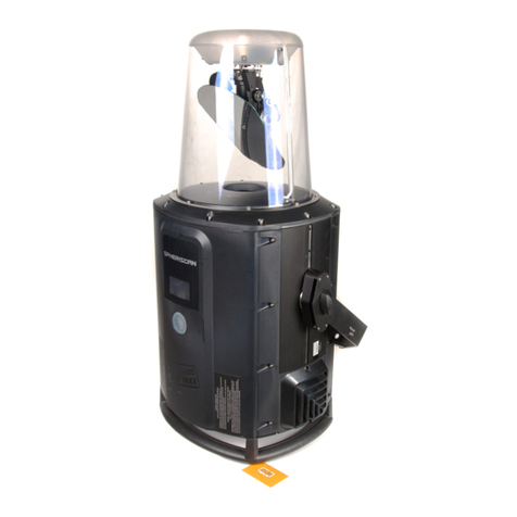
Claypaky SPHERISCAN C11260 User manual

Claypaky

Claypaky SPHERISCAN C11260 User manual

Claypaky AROLLA PROFILE MP User manual

Claypaky

Claypaky AROLLA PROFILE MP User manual

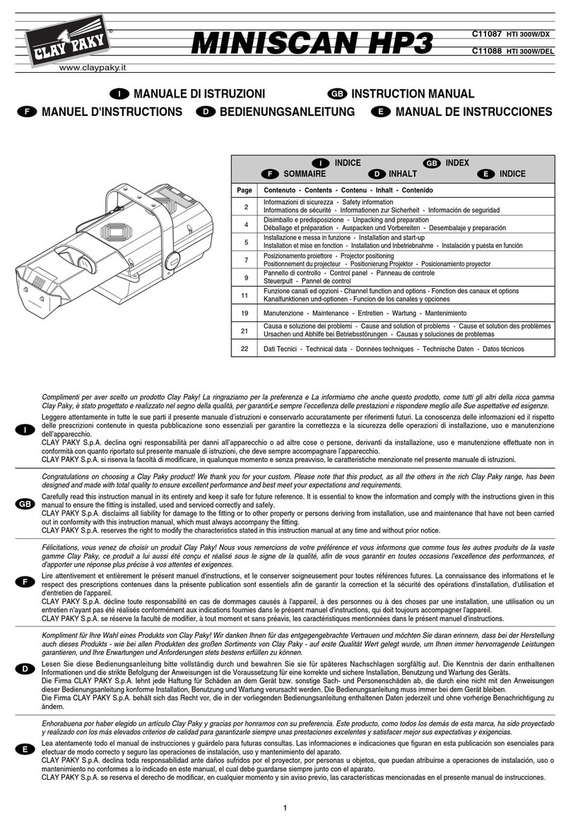
Claypaky MINISCAN HP3 User manual

Claypaky

Claypaky MINISCAN HP3 User manual

Claypaky A.LEDA WASH K10 CC User manual

Claypaky

Claypaky A.LEDA WASH K10 CC User manual

Claypaky C52162 User manual

Claypaky

Claypaky C52162 User manual

Claypaky Display Line C52146 User manual

Claypaky

Claypaky Display Line C52146 User manual

Claypaky TAMBORA LINEAR 100 User manual

Claypaky

Claypaky TAMBORA LINEAR 100 User manual

Claypaky C71050 User manual

Claypaky

Claypaky C71050 User manual

Claypaky ALPHA SPOT HPE 1500 User manual

Claypaky

Claypaky ALPHA SPOT HPE 1500 User manual

Claypaky A.LEDA WASH K5 C61401 User manual

Claypaky

Claypaky A.LEDA WASH K5 C61401 User manual

Claypaky CP COLOR 400 SH User manual

Claypaky

Claypaky CP COLOR 400 SH User manual

Claypaky PIN SCAN User manual

Claypaky

Claypaky PIN SCAN User manual

Claypaky Shary User manual

Claypaky

Claypaky Shary User manual

Claypaky ALPHA SPOT HPE 1500 ST User manual

Claypaky

Claypaky ALPHA SPOT HPE 1500 ST User manual

Claypaky C61092 User manual

Claypaky

Claypaky C61092 User manual

Claypaky ALPHA WASH 700 User manual

Claypaky

Claypaky ALPHA WASH 700 User manual

Claypaky ALPHA WASH 300 User manual

Claypaky

Claypaky ALPHA WASH 300 User manual

Claypaky HY B-EYE K15 User manual

Claypaky

Claypaky HY B-EYE K15 User manual

Claypaky ALPHA BEAM C61093 User manual

Claypaky

Claypaky ALPHA BEAM C61093 User manual

Claypaky ALPHA SPOT HPE 1500 User manual

Claypaky

Claypaky ALPHA SPOT HPE 1500 User manual

Popular Lighting Equipment manuals by other brands

EuroLite LED IP FL-10 COB RGB 120 with Remote user manual

EuroLite

EuroLite LED IP FL-10 COB RGB 120 with Remote user manual

ML Accessories ENM5 Installation & maintenance manual

ML Accessories

ML Accessories ENM5 Installation & maintenance manual

Smith-Victor LDS17 Assembly instructions

Smith-Victor

Smith-Victor LDS17 Assembly instructions

Renkforce 1228766 operating instructions

Renkforce

Renkforce 1228766 operating instructions

CR-Tec CR-LASER TOP-2 user manual

CR-Tec

CR-Tec CR-LASER TOP-2 user manual

Kaiser Fototechnik RB 5270 DX quick start guide

Kaiser Fototechnik

Kaiser Fototechnik RB 5270 DX quick start guide

Code 3 MEGA THIN Series Installation and operation instruction

Code 3

Code 3 MEGA THIN Series Installation and operation instruction

DL diode led installation guide

DL

DL diode led installation guide

Astera Lightdrop AX3 user manual

Astera

Astera Lightdrop AX3 user manual

Malatech Solarway 10 user manual

Malatech

Malatech Solarway 10 user manual

CircuPool RJ Classic Series troubleshooting guide

CircuPool

CircuPool RJ Classic Series troubleshooting guide

Uplus Lighting W3725 user manual

Uplus Lighting

Uplus Lighting W3725 user manual

EuroLite LED KLS-100 Lightset, including Case user manual

EuroLite

EuroLite LED KLS-100 Lightset, including Case user manual

Martin MAC Aura FX Guide

Martin

Martin MAC Aura FX Guide

ProLights MULTIFLOWER 102 user manual

ProLights

ProLights MULTIFLOWER 102 user manual

ADJ WiFly Bar RGBA User instructions

ADJ

ADJ WiFly Bar RGBA User instructions

EuroLite PAR-16 Spot user manual

EuroLite

EuroLite PAR-16 Spot user manual

Tranberg TEF 2870 user manual

Tranberg

Tranberg TEF 2870 user manual

manuals.online logo
manuals.online logoBrands
  • About & Mission
  • Contact us
  • Privacy Policy
  • Terms and Conditions

Copyright 2025 Manuals.Online. All Rights Reserved.