manuals.online logo
Brands
  1. Home
  2. •
  3. Brands
  4. •
  5. Curt Manufacturing
  6. •
  7. Automobile Accessories
  8. •
  9. Curt Manufacturing 52042 User manual

Curt Manufacturing 52042 User manual

CURTMFG.COM •PRODUCT SUPPORT: 877.287.8634 •52042-INS-RE •01/25/2023 •ECN10481 •PAGE 1
Product Registration and Warranty
CURT stands behind our products with industry-leading warranties. To get copies of the product
warranties, register your purchase or provide feedback, visit: warranty.curtgroup.com/surveys
INSTALLATION MANUAL 52042
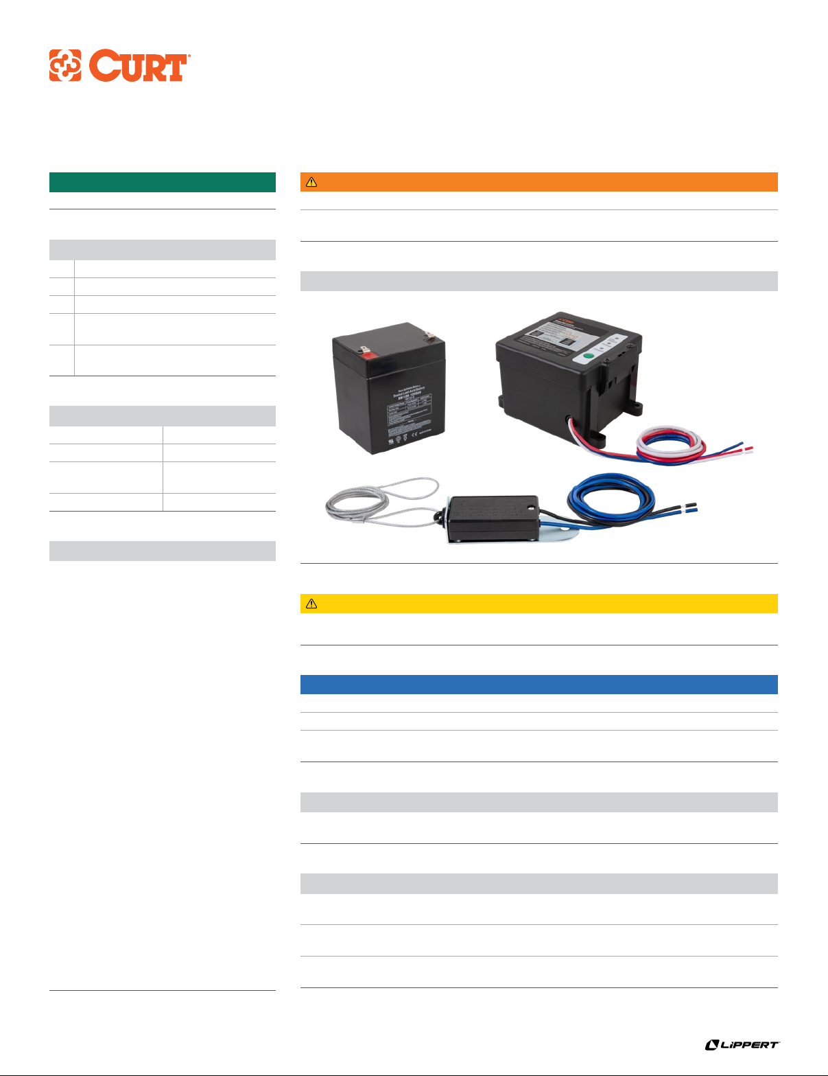
Product Photo
Level of Difficulty
Easy
WARNING
Never exceed the vehicle manufacturer's recommended towing capacity.
In order to avoid severe damage to the tow vehicle's electric brake controller, disconnect
the trailer connector from the tow vehicle prior to testing the breakaway system.
CAUTION
Do not attach the breakaway switch cable to
mounting hooks, trailer safety chains or the trailer ball.
Maintenance
Prior to each use, check the system's battery for operating voltage. Check that the breakaway
switch cables are not damaged from dragging on the ground and that they can move freely.
Check the breakaway system periodically to ensure proper and secure connections.
Open and / or short circuits may result in a no-brake situation.
Test the breakaway by pulling firmly on the cable of the
breakaway switch. The battery will activate the brakes.
NOTICE
Before you begin installation, read all instructions thoroughly.
Proper tools will improve the quality of installation and reduce the time required.
To help prevent damage to the product or vehicle, refer to the specified
torque specifications when securing hardware during the installation process.
Parts List
1Breakaway switch
1Battery case, charger & push-to-test
1Battery, 12V 5Ah gel cell
4Self-tapping screw with
hex head washer, 1/4"-14 x 1-1/4"
2Self-tapping screw with
hex head washer, 1/4"-14 x 3/4"
Functionality and Application
The breakaway kit uses a battery to engage
the trailer’s electric brakes if the trailer
becomes disconnected from the tow vehicle
while driving. The breakaway kit includes a
push-to-test battery testing system to allow
the charge level of the breakaway kit’s
battery to be verified before each use.
The breakaway battery when fully charged
will provide enough power to stop the
trailer and allow for time to add wheel
chocks to the wheels of the trailer in
the event of a breakaway situation.
Note: The trailer will not be held by
the breakaway kit indefinitely. Do not
use this kit as a trailer parking brake.
This breakaway kit is designed only for
one or two axle trailers installed with
electrical trailer brakes. Breakaway
kits are generally required with a trailer
of 3000 lbs. GTW or greater. Check your
local laws for specific requirements.
The built-in battery charging system will
recharge and maintain the breakaway
battery’s charge when the trailer’s 7-way
electrical connector is connected to a
running vehicle. The test button provides
an easy to read test of the state of
charge of the breakaway battery.
Tools Required
Drill Wire stripper
Drill bit, 9/32" Crimper
Phillips head
screwdriver
Waterproof butt
connectors
Wire cutter Ring terminal
CURTMFG.COM •PRODUCT SUPPORT: 877.287.8634 •52042-INS-RE •01/25/2023 •ECN10481 •PAGE 2
WIRING DIAGRAM
Step 2 - Wiring Breakaway Switch
Ensure the breakaway switch pin is fully installed.
Splice the blue wire from the breakaway switch to the
blue trailer brake wire from the breakaway battery box.
Splice the black wire from the breakaway switch
into the Trailer 7-way connector brake circuit.
The color of the brake circuit may vary trailer to trailer.
Step 1 - Mounting
Position the breakaway switch on the tongue of the trailer so that it
allows the cable to reach the tow vehicle's trailer hitch safety chain
eyelets. This is critical for proper engagement of switch.
Identify a suitable mounting location and drill a 9/32" hole
in the trailer frame to mount the breakaway switch. Use the
provided hardware to mount the switch to the trailer Note: Use
caution when drilling the hole, making sure there are no wires
or other objects behind the drilling surface. Do not to
over-tighten the bolt so the breakaway switch can pivot.
Find a suitable location on the trailer frame to mount the battery case.
Mount in a location that it does not interfere with the switch's lanyard.
Step 3 - Wiring Breakaway Battery Box
Splice the red battery positive wire from the breakaway battery box
to the Trailer 7-way connector 12V+ auxiliary power circuit. The color
of the 12V+ auxiliary power circuit may vary from trailer to trailer.
Attach the white wire from the breakaway battery box
to the trailer chassis using a ring terminal. Be sure the
attachment point is tight, clean and free of paint and rust.
Step 4 - Post-Installation Test
After the full installation of the breakaway kit following
steps 1 through 3, it is important to test the system.
Do not perform this test with the trailer’s
7-way connector connected to a tow vehicle.
Safely lift the trailer off the ground using a jack and jack stands
so that the wheels are can free spin without touching the ground.
Spin a trailer wheel and pull the pin on the breakaway switch.
The wheel should immediately stop spinning simulating
trailer brake application during a trailer breakaway situation.
Verify the brakes are applied by attempting to
rotate the wheels. Leave the breakaway pin pulled
with the trailer brakes applied for 15 minutes.
After 15 minutes, again attempt to rotate
the wheels. The trailer brakes should still be
applied and the wheels should not be able to spin.
Reinsert the breakaway switch pin.
Safely lower the trailer back to the ground.
After performing the post-installation test, the
breakaway battery will need to be recharged before
first use. See the Battery Charging and Maintaining section.
CURTMFG.COM •PRODUCT SUPPORT: 877.287.8634 •52042-INS-RE •01/25/2023 •ECN10481 •PAGE 3
Preparation for Use when Towing
Check the breakaway system wiring and switch before each
use to ensure secure connections and proper operation.
Open and / or short circuits may result in a no-brake situation.
Always check the breakaway battery charge level using the Test
button on the breakaway battery box prior to connection for towing.
The Test button should only be used when the trailer’s 7-way
connector is disconnected from the tow vehicle. Failure to
do so may damage the system and prevent proper operation.
Test the breakaway system by pulling firmly on the
cable of the breakaway switch. The battery will activate
the brakes when the breakaway switch pin is pulled out.
Do not use this kit as a parking brake.
When preparing to tow a trailer with the breakaway kit installed,
plug the 7-way trailer electrical connector into the tow vehicle
as normal. The yellow Charging LED may be illuminated on
the breakaway battery box. Attach the breakaway switch
cable to a suitable location on the frame of the tow vehicle.
Do not attach the breakaway switch cable to mounting hooks,
trailer safety chains, or the trailer ball. Ensure the breakaway switch
cable is mounted in a location which will not become dislodged
from the tow vehicle and that the cable will not accidently
pull the breakaway switch pin during normal vehicle motion.
Do not attach the breakaway switch cable to
mounting hooks, trailer safety chains or the trailer ball.
In order to avoid severe damage to the tow vehicle's
electric brake controller, disconnect the trailer connector
from the tow vehicle prior to testing the breakaway system.
Breakaway Battery Charging and Maintaining
When the red recharge LED is illuminated,
the breakaway battery requires charging.
To do so, connect the 7-way trailer electrical connector to
a tow vehicle. Turn the tow vehicle on and leave running for
10 to 15 minutes to allow for the breakaway battery to recharge.
After the charging cycle, turn the tow vehicle off and disconnect
the 7-way connector from the tow vehicle. Wait two minutes until
pressing the test button. The green “Fully Charged” LED should now
be illuminated when pressing the Test button for five seconds.
The breakaway kit charging system will maintain the breakaway
battery level when towing the trailer regularly. It is recommended
to remove the battery and use a battery maintainer if the
trailer is going to be stored for a long period of time.

Other Curt Manufacturing Automobile Accessories manuals

Curt Manufacturing 16320 User manual

Curt Manufacturing

Curt Manufacturing 16320 User manual

Curt Manufacturing 16600 User manual

Curt Manufacturing

Curt Manufacturing 16600 User manual

Curt Manufacturing 51453 User manual

Curt Manufacturing

Curt Manufacturing 51453 User manual

Curt Manufacturing 16050 User manual

Curt Manufacturing

Curt Manufacturing 16050 User manual

Curt Manufacturing 12170 User manual

Curt Manufacturing

Curt Manufacturing 12170 User manual

Curt Manufacturing 4516 User manual

Curt Manufacturing

Curt Manufacturing 4516 User manual

Curt Manufacturing A25 User manual

Curt Manufacturing

Curt Manufacturing A25 User manual

Curt Manufacturing 18100 Operator's manual

Curt Manufacturing

Curt Manufacturing 18100 Operator's manual

Curt Manufacturing 58957 User manual

Curt Manufacturing

Curt Manufacturing 58957 User manual

Curt Manufacturing 2060 User manual

Curt Manufacturing

Curt Manufacturing 2060 User manual

Curt Manufacturing 4501 User manual

Curt Manufacturing

Curt Manufacturing 4501 User manual

Curt Manufacturing 31048 User manual

Curt Manufacturing

Curt Manufacturing 31048 User manual

Curt Manufacturing 13434 User manual

Curt Manufacturing

Curt Manufacturing 13434 User manual

Curt Manufacturing ECHO User manual

Curt Manufacturing

Curt Manufacturing ECHO User manual

Curt Manufacturing Rebellion XD User manual

Curt Manufacturing

Curt Manufacturing Rebellion XD User manual

Curt Manufacturing 11419 User manual

Curt Manufacturing

Curt Manufacturing 11419 User manual

Curt Manufacturing ECHO User manual

Curt Manufacturing

Curt Manufacturing ECHO User manual

Curt Manufacturing 13277 User manual

Curt Manufacturing

Curt Manufacturing 13277 User manual

Curt Manufacturing 58963 User manual

Curt Manufacturing

Curt Manufacturing 58963 User manual

Curt Manufacturing 13454 User manual

Curt Manufacturing

Curt Manufacturing 13454 User manual

Curt Manufacturing Quick Goose II User manual

Curt Manufacturing

Curt Manufacturing Quick Goose II User manual

Curt Manufacturing 55525 User manual

Curt Manufacturing

Curt Manufacturing 55525 User manual

Curt Manufacturing 13287 User manual

Curt Manufacturing

Curt Manufacturing 13287 User manual

Curt Manufacturing LIPPERT 18109 User manual

Curt Manufacturing

Curt Manufacturing LIPPERT 18109 User manual

Popular Automobile Accessories manuals by other brands

Magneti Marelli AC161 Installation instruction

Magneti Marelli

Magneti Marelli AC161 Installation instruction

FDI uEZ GUI Start here

FDI

FDI uEZ GUI Start here

JCROffroad JT Install instructions

JCROffroad

JCROffroad JT Install instructions

Rostra VOXXElectronics 250-1930 owner's guide

Rostra

Rostra VOXXElectronics 250-1930 owner's guide

TOP VEHICLE TECH GR3FORD5 installation manual

TOP VEHICLE TECH

TOP VEHICLE TECH GR3FORD5 installation manual

Safe Fleet PRIME DESIGN AR-2000-BLK manual

Safe Fleet

Safe Fleet PRIME DESIGN AR-2000-BLK manual

Skoda Fabia Combi 5J Fitting instructions

Skoda

Skoda Fabia Combi 5J Fitting instructions

Camcar 40077 Al Mounting instructions

Camcar

Camcar 40077 Al Mounting instructions

Camcar 40089 AL Mounting instructions

Camcar

Camcar 40089 AL Mounting instructions

Impac Tradesman 2000 installation manual

Impac

Impac Tradesman 2000 installation manual

DVB OFFROAD BRSB-01 installation manual

DVB

DVB OFFROAD BRSB-01 installation manual

Safari Snorkel SS385HF installation guide

Safari Snorkel

Safari Snorkel SS385HF installation guide

ULTIMATE SPEED 279746 Assembly and Safety Advice

ULTIMATE SPEED

ULTIMATE SPEED 279746 Assembly and Safety Advice

SSV Works DF-F65 manual

SSV Works

SSV Works DF-F65 manual

ULTIMATE SPEED CARBON Assembly and Safety Advice

ULTIMATE SPEED

ULTIMATE SPEED CARBON Assembly and Safety Advice

Witter F174 Fitting instructions

Witter

Witter F174 Fitting instructions

WeatherTech No-Drill installation instructions

WeatherTech

WeatherTech No-Drill installation instructions

TAUBENREUTHER 1-336050 Installation instruction

TAUBENREUTHER

TAUBENREUTHER 1-336050 Installation instruction

manuals.online logo
manuals.online logoBrands
  • About & Mission
  • Contact us
  • Privacy Policy
  • Terms and Conditions

Copyright 2025 Manuals.Online. All Rights Reserved.