curt 51515 User manual

ADVANCED ELECTRONIC ACCELEROMETER TRAILER BRAKE CONTROL
INSTALLATION AND USER GUIDE
For use with 12 volt negative ground systems only
For trailers with 2 – 8 brakes
Read, follow and save this guide for future reference.
BRAKE CONTROL
51140

This package includes:
(1) Brake control module with quick plug
(1) Mounting bracket
(6) Screws
(1) Quick setup reference card
One or more of the following will also be needed to complete installation
- Brake control connection harness supplied with the tow vehicle (if equip’d)
- CURT quick plug – custom connector for specic vehicles.
See catalog for availability
- CURT part number 51515 or 51516 male quick plug with pigtails
- CURT part number 51500 brake control wiring kit
Important Information
- CAUTION: Read and follow installation and setup instructions carefully.
Failure to do so could result in damage to the brake control unit, no trailer
brakes or poor brake performance.
- CAUTION: Disconnect the electrical plug between the trailer and tow
vehicle before testing a breakaway switch. Failure to disconnect may
damage the brake control unit.
- CAUTION: Avoid mounting the brake control module near a CB radio or other
RF transmitter.
- WARNING: The brake control unit must be mounted rmly in place.
Failure to do so could lead to improper operation and/or brake failure.
- WARNING: The brake control unit’s positive (with 30 amp circuit breaker)
and ground wires must be connected directly to the tow vehicle’s battery

using 10 gauge minimum stranded wire. Connecting to existing wiring or an
alternate ground may damage vehicle circuits, lead to failure of the brake
control module, loss of trailer brakes or vehicle re.
- NOTICE: Removal of the factory supplied quick plug can void warranty.
Features
- Digital display provides detailed brake force output and sensitivity position
- Provides automatic and manual trailer braking
- Switchable manual control output, 100% or limited to output setting
- Switchable manual control brake light activation or no brake light activation
- Compatible with electronic systems (anti-lock brakes & cruise control)
- Protected against reverse voltage, voltage spikes, shorts, and overloads
- Power conservation mode after 15 minutes of inactivity, wakes when brake
pedal is pushed
- Display is capable of communicating operational errors
- Reduced output when sitting still (railroad crossing, stoplight, etc…)
- Automatically compensates for uphill and downhill road conditions
- Will work with most electrically activated hydraulic trailer brake systems
- Includes quick plug for fast and easy connection to many vehicles
(see catalog for application specic harnesses)

Controls and Components
1. Digital display
2. Sensitivity adjustment
3. Output adjustment thumbwheel
4. Manual control lever
5. Quick plug connector
6. Switch for manual control max output, 100% or output setting
7. Switch manual control stoplight activation
8. Mounting bracket
1 8
6 7
2
3
45

Controls and Display
Output Control
The output control thumbwheel establishes the maximum amount of power
available to the trailer brakes when braking. The only exception would be when
the manual control is setup for 100% braking, see "Set manual control out-
put and brake light switches".
As the output control is rotated, a ashing display shows the setting. When
turned to the right, more power will be available to the brakes when turned to
the left, less power will be available.
Display ashes the setting for a few seconds after adjustment is complete.
The output control would be adjusted during initial setup, when trailer load
changes, when different trailers are used or when adjustment is needed for
changing road or driving conditions.
The output setting is shown on the display when a trailer is connected and the
brake pedal is pressed or the manual control is actuated. The output setting is
shown as through
Sensitivity Control
The sensitivity control adjusts trailer brake aggressiveness. The trailer brakes
become more aggressive as the switch is moved toward the driver.
To view the sensitivity setting on the display, move the control slightly. The set-
ting will ash.
Sensitivity adjustment has no effect on the manual control. The sensitivity
control would be adjusted for individual driver preference, trailer load changes
or changing road conditions.

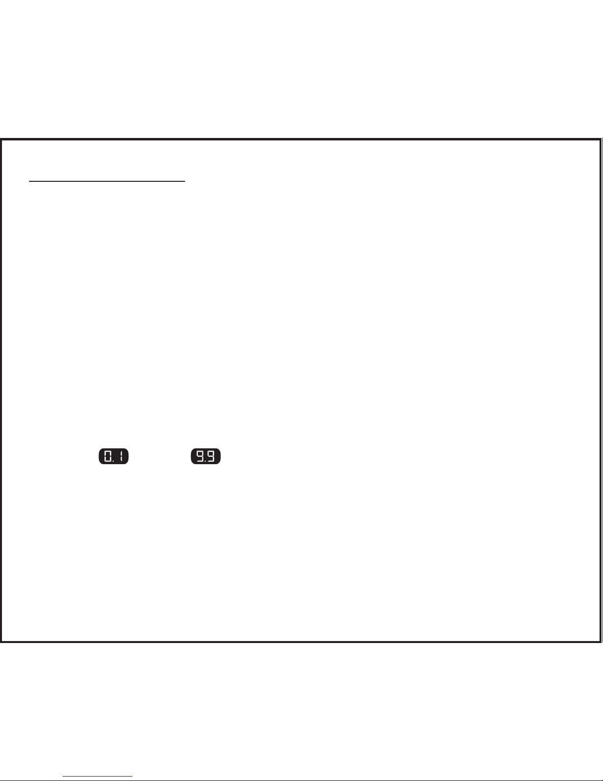
The sensitivity control setting is shown as through with being
the least aggressive and being the most aggressive.
The display ashes the setting for a few seconds after adjustment is complete.
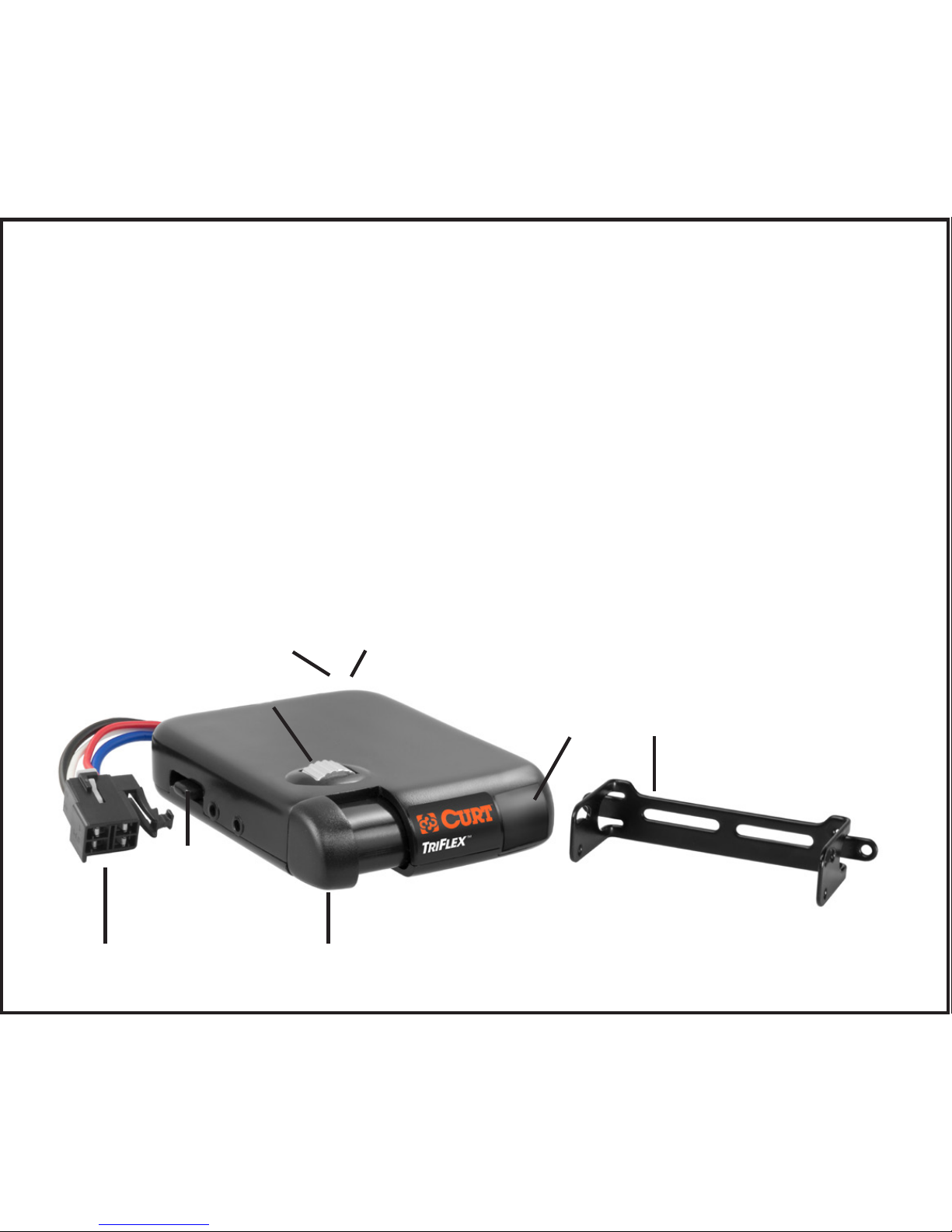
Manual Control
The manual control is located on the front of the brake control unit at the left side.
The manual control only applies trailer brakes. Manual is used during initial
setup and in situations where a slow reduction in speed is desirable.
As the manual control is pushed to the right, the control begins to apply the trail-
er brakes. The further to the right it is pushed the harder the brakes are applied.
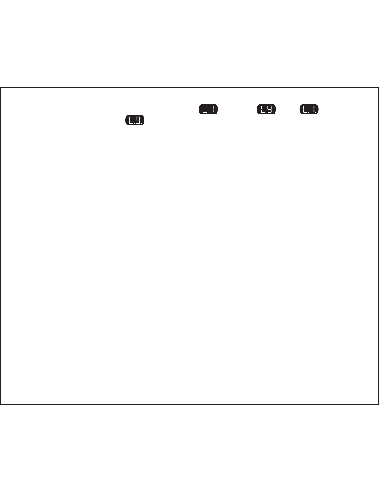
The manual control can be setup to either allow 100% of the unit’s power to the
trailer brakes or to limit power to the output control setting. This feature is setup
at installation via a small switch at the rear of the unit. See "Set manual con-
trol output and brake light switches". The brake control unit is shipped from
the factory with the switch in the limited to the output control setting position.
Output will be shown on the display when the manual control is actuated.
Brake light activation with the manual control is also an optional setting. Some
tow vehicle’s circuits do not allow power for brake lights from a second source.
In these applications, the brake light feature can be switched off using a second
small switch at the rear of the unit. The brake light connection (red wire) is still
required to activate the TriFlex brake control with the switch in either position.
See "Set manual control output and brake light switches". The brake
control unit is shipped from the factory with the switch in the activate brake light
position.

Digital Display
The digital display shows the output setting when the control is activated. It
is used to setup and monitor the brake control and can be used when trouble
shooting.
Standby mode, no trailer connected
Standby mode, trailer connected
Trailer connected, brakes activated
Flashing, output adjustment mode
Flashing, sensitivity adjustment mode
Trailer connected, checking calibration
Flashing, trailer disconnected,
off after 60 seconds
Recalibration needed,
unplug and replug trailer connector
Calibrating
Overloaded output circuit,
trailer brake system fault
Low voltage, tow vehicle system
Blank display, does not illuminate when
control is activated, check installation
Blank display, standby mode,
illuminates when control is activated
Accelerometer error,
powers brakes using default values
Stoplight wire (red) shorted to ground

Installation
Set Manual Control Output and Brake Light Switches
There are two small switches located at the rear of the unit that can be ac-
cessed by removing the rectangular cover. Once accessed, the switch positions
can be changed using a small pointed tool.
In the illustration above the switch on the right controls the level of output avail-
able to the trailer brakes when using the manual control. The factory default
setting is the "ON" position with the switch down. This setting limits the manual
control output to the level set using the output control thumbwheel. Moving this
switch up to the "OFF" position allows 100% of the output to the brakes when
the manual control is actuated regardless of the output control setting.
In the illustration above the switch on the left controls the unit’s brake light ac-
tivation feature. The factory default setting is the "ON" position with the switch
down. This setting activates the tow vehicle and trailer brake lights when the
manual control is actuated. Moving the switch up to the "OFF" position turns off
the brake light activation feature and the brake lights are not activated when the
manual control is actuated.

Mounting
1. Determine a suitable mounting location.
A) The unit must be mounted securely to a solid surface.
B) The unit must be easily reached by the driver.
C) The area behind mounting location must be clear so no damage will be
done when drilling.
20° 20°
T
RI
F
LEX
TM
T
RI
F
LEX
TM
TRIFLEX
TM
20° 20°
70°
20°

2. Hold the mounting bracket in the position selected and mark the hole
locations through the bracket.
3. Using a 1/8" diameter bit, drill holes in the marked locations.
4. With a screwdriver or a 1/4" nut driver, secure the bracket in place using
(2) self threading screws (provided). Do not over-tighten.
5. Mount the brake control unit in the bracket using (4) screws.
Wiring
Disconnect the tow vehicle’s negative battery terminal from its battery
post before beginning the wiring process.
Tow vehicles equipped with a factory brake control plug:
Most late model pickups and utility vehicles are equipped with a plug that
allows quick brake control installation. Check the owner’s manual for plug avail-
ability, location and installation.
If the mating plug supplied with the vehicle is no longer available, a CURT quick
plug can be used (see CURT catalog for application information).
Tow vehicles not equipped with a factory brake control plug:
Suggested: CURT part number 51500 brake control wiring kit.
Mount a 30 amp, auto reset, circuit breaker as close to the battery as possible.
IMPORTANT: When passing wire through sheet metal, always go through an
existing grommet, add a grommet, or use silicone sealer to protect the wire from
sharp edges.

Feed two 10 gauge wires, one white and black, from the mounted brake control
to the battery area. Using a ring terminal, connect the black wire to the "AUX"
side of the 30 amp circuit breaker. Leave the white wire to be connected later.
Using a 10/12 gauge butt connector, attach the black wire from the "AUX" side
of the 30 amp circuit breaker to the brake control module’s black wire. Again
using a 10/12 gauge butt connector, attach the white wire from the battery area
to the module’s white wire.
Wiring Diagram

Run a 10 gauge blue wire from the tow vehicle’s trailer plug "brake" terminal to
the brake control module. Using a 10/12 butt connector, connect this wire to the
module’s blue wire
NOTE: Stoplight switch connection on Ford vehicles including, Mercury
Mountaineer. Do not connect to the red wire with a green stripe.
Connect to the light green wire only.
For vehicles other than 1989-1991 Ford E and F Series trucks and
vans with anti-lock brakes: use a test probe, determine which wire on the
tow vehicle’s stoplight switch is only "hot" when the pedal is pressed. Splice the
module’s red wire to this wire using a wire tap.
For 1989-1991 Ford E and F Series trucks and vans with anti-lock brakes:
Find the crescent shaped connector located on the steering column, the connec-
tor has two rows of wires. The wire needed is the light green wire, second from the
end in the outside row of seven wires (see the box shown in wiring the diagram).
Splice the brake control module’s red wire to light green wire using a wire tap.
Using 10 gauge stranded wire and ring terminals, connect the "BATT" side of
the circuit breaker to the positive battery terminal.
Attach the white 10 gauge wire previously positioned near the battery to the
negative battery terminal using a ring terminal. Reconnect the tow vehicle’s
negative battery terminal to its battery post. See vehicle’s owner’s manual for
special battery re-connection instructions.
Test the installation: Without a trailer connected, push the brake pedal. A single
(decimal point) should light up on the display. If the decimal point does not
light or if , or is shown refer to display messages. After testing
secure all loose wires with cable ties so that they will not be damaged.

Setup
Once all electrical connections are complete and the single decimal point is
seen, while parked on a level surface, plug the trailers electrical connector into
the tow vehicle’s plug.
Making the trailer connection initiates the mounting position calibration mode.
C.C may be seen on the display followed by either or . If ap-
pears, recalibration is needed. To recalibrate, unplug and replug the trailer’s
electrical connector. While calibrating, the display will show or may ash
the Output setting. When
appears, the unit is calibrated and ready for setup.
Make the following preliminary adjustments with the trailer connected and
engine running to ensure proper charge voltage. The vehicle must be in park or
neutral with the parking brake applied, foot off the brake pedal, and no manual
control actuation:
Adjust output to by turning the output control wheel left or right as needed.
Adjust sensitivity to by moving the sensitivity control forward or back.
Test Drive and Adjustment
Both output and sensitivity can be adjusted to achieve smooth rm stops.
Output and sensitivity adjustments should only be made while stopped, with the
transmission in park or neutral, parking brake applied, foot off the brake pedal,
and no manual control actuation.
Output and sensitivity settings will ash while adjustments are made and for a
few seconds after.
Start with the output adjustment. Drive forward on a paved or concrete surface

that is dry and level. At approximately 25 MPH, apply the tow vehicle brakes. If
trailer braking is insufcient, adjust the output control to the right. If the trailer
brakes lockup adjust the output control to the left. Repeat this step until stops
are rm, just short of lockup.
Once the output is set, adjust sensitivity. Drive forward to approximately 25 MPH
and press the brake pedal. Tow vehicle and trailer should make smooth stops.
If the stops seems slow and more aggressive braking is desired, move the sensi-
tivity control toward the driver.
If the stop seems too aggressive adjust the sensitivity control away from the driver.
Make several stops at various speeds and adjust sensitivity until stops are
smooth and rm. Slight adjustment the output control may also be desirable.
NOTE: If any problems occur during setup refer the trouble shooting section of
these instructions.
Helpful Tips
Light pressure on the manual control will activate the trailer’s brakes with no
effect on the tow vehicle’s brakes. This is useful for gradual slowing on steep
grades or before stops.
Periodic adjustment of the output and sensitivity controls may be necessary to
correct for changing road conditions, trailer loading, brake wear, or driver prefer-
ence.
In some applications, when towing with hazard ashers on, the digital display will
ash with the hazard ashers. If the brake control is set aggressively pulsing
may
be felt in the trailer brakes.

TROUBLESHOOTING GUIDE (TEST WITHOUT TRAILER FIRST):
No trailer connected
CONDITION DISPLAY PROBABLE CAUSE POSSIBLE SOLUTION
Decimal point does not light Blank No power to control, no
ground, reversed black and
white wires
Check brake control
wiring
Decimal point on after 12 – 15
minutes of inactivity
Decimal Red wire connected to
wrong side of stoplight
switch or to wrong wire
Check brake control
wiring
Display shows output power
when brake pedal is pushed or
manual control is actuated
Output Power
Not blinking
Brake control unit mis-
wired or contamination in
trailer plug socket
Check brake control
wiring, clean and dry
trailer plug
Display shows L.b
Can also happen with trailer
connected
Tow vehicle’s system
voltage low
Check tow vehicle’s
battery and charging
system
Display shows E.1. when
manual control is applied
Red wire connected to
ground side of stoplight
switch or is shorted to
ground
Check brake control wir-
ing, may require change
to switch setting. See
"manual control" section
Display shows OL when brake
pedal or manual override
is used
Blinking Short in blue wire output
circuit or trailer plug
Locate and correct short

With trailer connected
This guide is for reference only. If problems persist, see a professional installer.
CONDITION DISPLAY PROBABLE CAUSE POSSIBLE SOLUTION
Display shows only 1
decimal point when power is
applied to control. No trailer
brakes when brake pedal or
manual control is used
Decimal No connection between
brake control and trailer
brakes – Blue wire circuit
Confirm connection to trailer
connector. Confirm connector
terminal positions.
Check trailer
No trailer brakes,
pedal or manual
Output power
Not blinking
Mis-wired trailer
connector
Confirm trailer connector
terminal positions
No trailer brakes,
pedal or manual
Blinking Short or overload
in trailer brakes
Troubleshoot trailer brake cir-
cuit per brake manufacturer’s
instructions
Weak or no trailer brakes
or trailer lights illuminate
with brakes
Output power
Not blinking
Mis-wired trailer Check and correct
trailer wiring
Trailer brakes on all the time During standby mode
During sleep mode
Mis-wired trailer
connector
Check and correct
connector wire positions
Display shows A.E.
after releasing brake
Internal error Replace brake control unit
No trailer brakes,
pedal or manual
Blinking Loss of trailer connection,
unplugged or bad wiring
Stop and check
trailer connector
This manual suits for next models
1
Table of contents
Popular Automobile Electronic manuals by other brands

Directed Electronics
Directed Electronics VIPER 5101 owner's guide

Adaptiv Mini
Adaptiv Mini CAM-PO3-AD user guide

Conrad
Conrad 85 69 98 operating instructions

NOVAK
NOVAK ROOSTER CRAWLER - ADDENDUM Product features

Dometic
Dometic MAGICWATCH MWE820 Installation and operating manual

Car Solutions
Car Solutions AUDI 4G PAS manual