Table 1: Command Word Bit Assignments and Denitions. .................................................................. 7
Table 2: CAN Object Dictionary .......................................................................................................... 8
Table 3: ASCII Character Table ........................................................................................................... 13
Table 4: Specications....................................................................................................................... 14
Figure 1: Curtis Model 3140 ............................................................................................................... 1
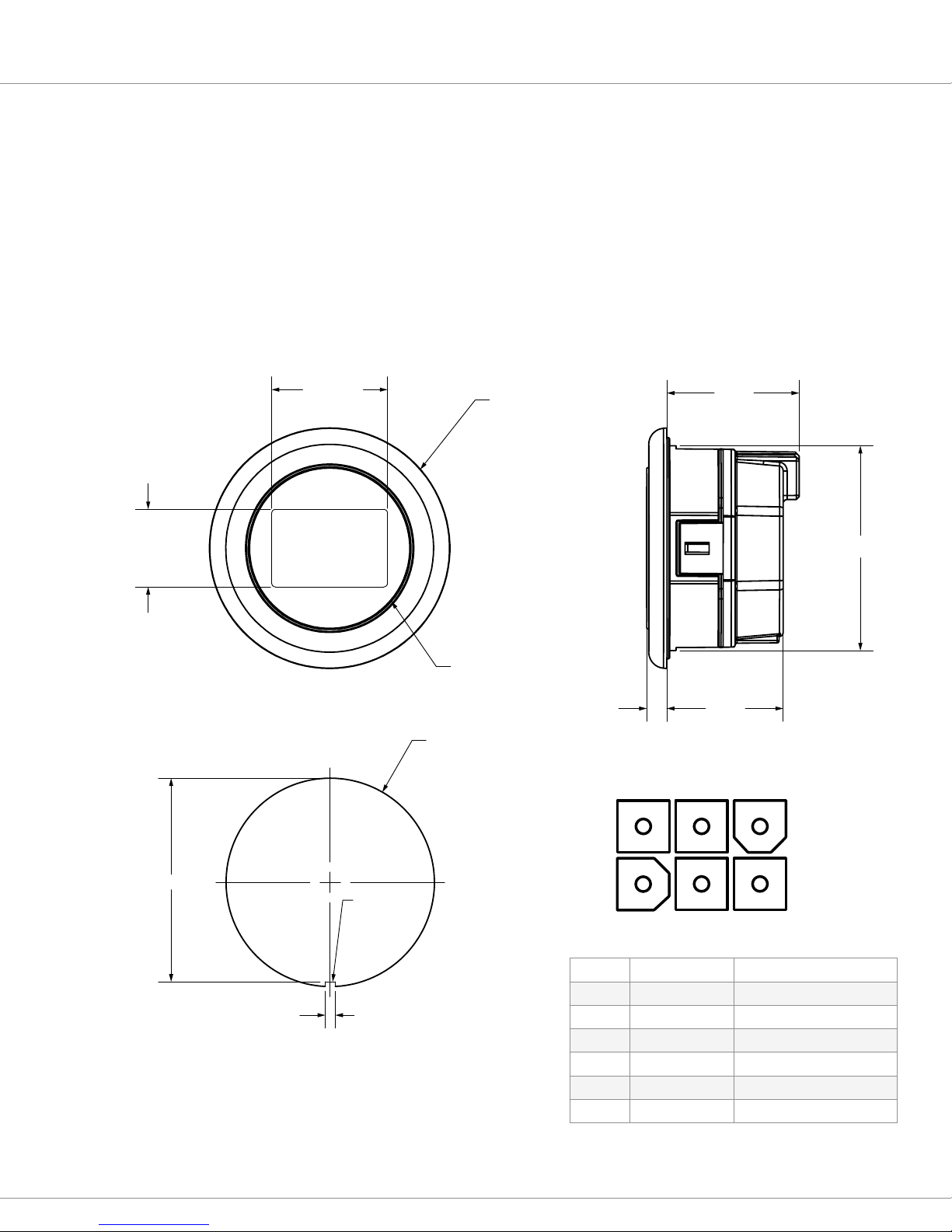
Figure 2: 3140 Dimensions ................................................................................................................ 2
e 3140 includes the following:
• Integrates seamlessly with Curtis Model F2A (and other CANopen-based motor controllers) thereby
reducing the amount of development work by the vehicle designer.
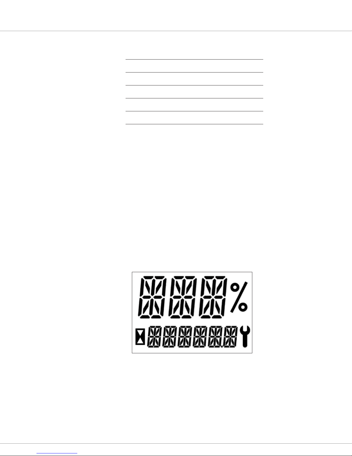
• Attractive xed-segment, transective LCD with 16-segment digits and informative icons allows
intuitive reading in all lighting conditions and battery-powered vehicle environments.
• Optional integral CAN termination resistor allows exibility in customer vehicle design.
• Industry standard 52mm panel cutout allows the use of exising panel/tool designs thereby lowering
development cost.
• Battery State-of-Charge (BSOC) can be calculated in the 3140 or sent to the 3140 by the Model F2A
(or equivalent CANopen-based motor controller).
• In addition to the 3 and 6 digit portions of the LCD, a percent symbol, wrench symbol, hourglass
icon and decimal point are also present which provides more comprehensive information about
vehicle status.
• Single unit operates from 24, 36, to 48 VDC allowing use on many models of battery-powered vehicles.
• Optional backlighting and LCD heater allow use in low-light and cold-store applications.
• Integrated 6-pin Mini-Universal MATE-N-LOCK connector allows for an easy and environmentally
protected connection.
• Environmentally protected (IP65 front, IP54 rear) to allow use in harsh environments.
• CE compliance, UL recognition and RoHS2 compliance ensure compatibility with global
regulatory standards.
CANopen Convenience
Model 3140 is CANopen compliant, responding to the
standard NMT, PDO and SDO communications as well
as the DS301 required identity and standard objects.
The Curtis CANopen extensions allow additional
features, such as OEM and User default congurations.
Model 3140 will receive a single SDO and respond with
a single SDO. ese SDO’s are xed, simplifying the
interface to a VCL-enabled device. All programmable
parameters and viewable values within the 3140 are
accessible via standard SDO transfer.
1—INTRODUCTION pg. 1
1—INTRODUCTION
e Curtis Model 3140 CAN instrument is designed to display critical vehicle and motor controller data
on an easy-to-read and attractive LCD. e display includes three 10mm digits and six 5mm digits and all
digits are in 16-segment format to allow use of the full alpha numeric character set. Model 3140 integrates
seamlessly with Model F2A and other CANopen-based motor controllers.
Figure 1
Curtis model 3140
CAN instrument.