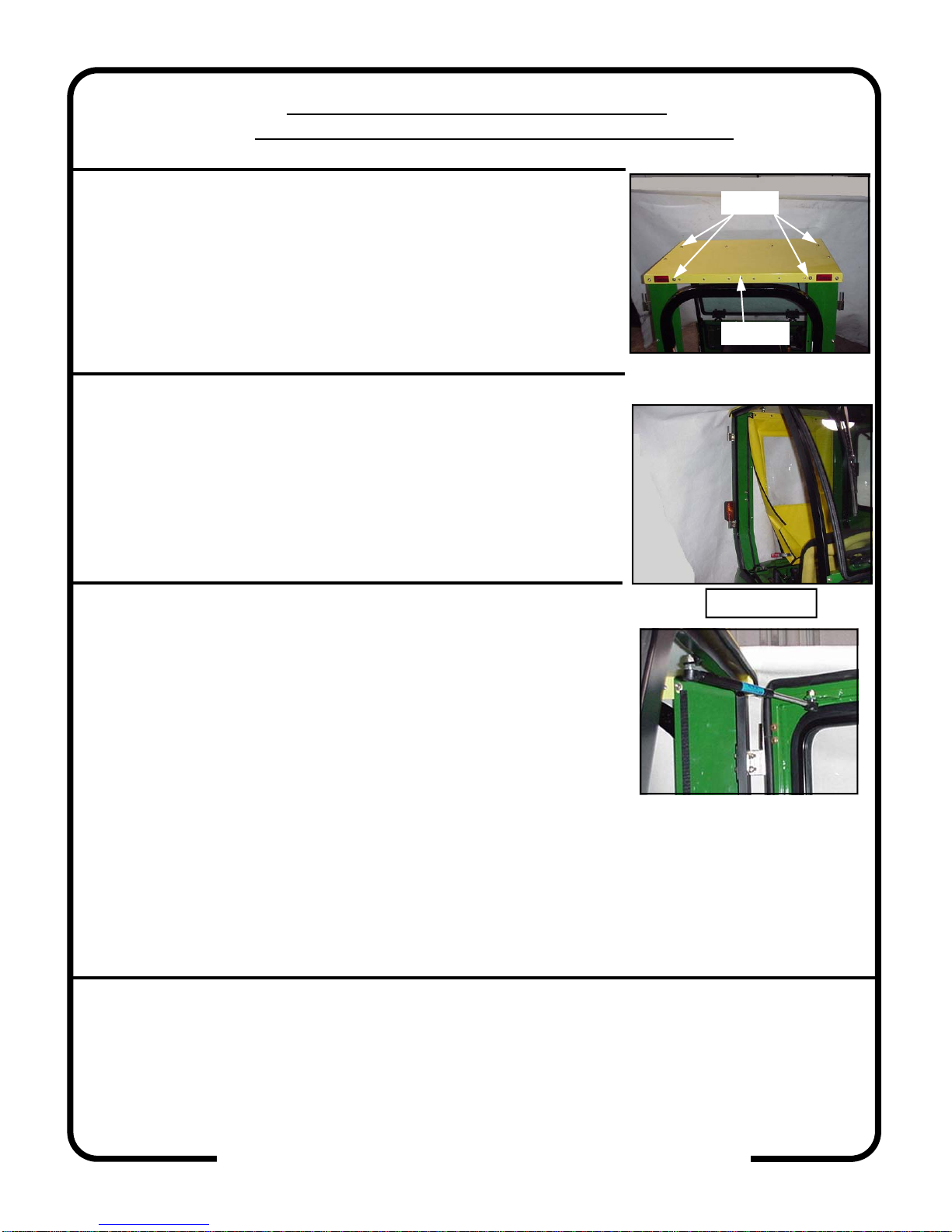
Curtis 1JD2305AS User manual

INSTALLATION & OWNER’S MANUAL
The contents of this envelope are the property of the owner.
Be sure to leave with the owner when installation is complete.
CAB INSTALLATION INSTRUCTIONS
JOHN DEERE 2305, 2210
HARD SIDED CAB ENCLOSURE (p/n 1JD2305AS)
SOFT SIDED CAB ENCLOSURE (p/n 1JD2305SS)
This Curtis Cab is designed and
manufactured for use only as reasonable
weather protection. This cab is not appli-
cable, Nor should the cab be considered as protection against
roll over, collision or other accidents that may result. This cab is
NOTaR.O.P.S.cab. Extreme care should be taken when operat-
ing and by qualified, experienced operators only.
ExposuretoCarbonMonoxidecanCause
illness,seriousinjuryordeath.Never
operate vehicle if suspicious of Carbon
Monoxide. Inspect exhaust system for leaks monthly. Leaks can
result from loose connections, corrosion, cracks or other damage
to the exhaust manifold. If leaks are found, repair or replace
exhaust system. Do not use vehicle until repair or replacement is
complete.
p. 1 of 8, Rev. J,
1/3/2012
CABS/BLADES/ SPREADERS/ACCESSORIES
driver and passenger.
Curtis accessory weights are listed in product
add additional weight to the base vehicle. All
Curtis Cabs, blades and general accessories
ADDED
WEIGHT
brochures. Deduct the accessory's total weight
from the vehicle's rated capacity and never
exceed the vehicle's rated capacity including
Note: soft side cab shown
p/n: IM-1JD2305

DESIGN CONCEPT
Curtis Cabs feature an assembly of parts designed for your vehicle which require
adjustment and alignment of components to accommodate vehicle variations and
provide proper weather protection. For accurate installation, proper operation, and
years of satisfaction, please read and understand the installation instructions.
From all of us at Curtis, we thank you for choosing our product.
CAB INSTALLATION
BEFORE YOU START
HELPFUL REMINDERS:
A. Leave all bolts loose for later adjustment unless otherwise specified.
B. Read and understand all instructions before beginning.
C. Plastic washers have been supplied to provide a weather seal around
all button head exterior fasteners. The plastic washer should be installed
under each bolt head directly against the outside cab surface. Care
should be taken not to over tighten the fasteners and damage the plastic
washer. Also use metal washers as required.
D. Apply a clear silicone sealant to seal any minor gaps that may occur due
to vehicle variances. E.G. front legs to bottom of unitized frames.
TOOLS REQUIRED:
This Curtis Cab is designed and manu-
factured for use only as reasonable
weather protection. This cab is not applicable, nor should
the cab be considered as protection against roll over,
collision or other accidents that may result. This cabs is
NOTaR.O.P.S.cab. Extreme care should be taken when
operating and by qualified, experienced operators only.
ExposuretoCarbonMonoxidecan
Causeillness,seriousinjuryordeath.
Never operate vehicle if suspicious of Carbon Monoxide.
Inspect exhaust system for leaks monthly. Leaks can result
from loose connections, corrosion, cracks or other damage
to the exhaust manifold. If leaks are found, repair or replace
exhaust system. Do not use vehicle until repair or replace-
ment is complete.
driver and passenger.
Curtis accessory weights are listed in product
add additional weight to the base vehicle. All
Curtis Cabs, blades and general accessories
ADDED
WEIGHT
brochures. Deduct the accessory's total weight
from the vehicle's rated capacity and never
exceed the vehicle's rated capacity including
7/16 IN.
OPEN END
WRENCH
1/2 IN.
OPEN END
WRENCH
7/16 IN.
3/8 DRIVE
SOCKET
1/2 IN.
3/8 DRIVE
DEEP
SOCKET
3/8 DRIVE
RATCHET
NO. 2 MEDIUM
PHILLIPS HEAD
SCREWDRIVER
p. 2 of 8
3/16 INCH
ALLEN
DRIVE
3/8 DRIVE
12 mm
3/8 DRIVE
SOCKET
18 mm.
3/8 DRIVE
SOCKET
13 mm
3/8 DRIVE
SOCKET
13 mm
OPEN END
WRENCH
SNIPS

111 HIGGINS STREET, WORCESTER, MA 01606
MODEL: JOHN DEERE 2305, 2210 HARD SIDE & SOFT SIDE CABS
CABS/BLADES/ SPREADERS/ACCESSORIES
NOTE: This cab is designed to fit the 2210 and 2305 tractors
with 210, 200X or 200CX loaders. It may or may not fit with oth-
er attachments or aftermarket loaders.
1. VEHICLE PREP
1.1 Remove SMV sign and bracket. On 2305 models r-install the turn
signal light with the hardware removed with the SMV bracket.
1.2 (See figure 1) Remove and discard bolts from the tractor floorboard
as shown. There are 2 bolts on the left side but only one on the right
side.
1.3 (See Figure 1) Remove seat belt holder bracket and the bolt next to
it from the base of the roll bar on both sides of the tractor. Retain for
later use.
1.4 (See Figure 2) The plastic floorboard of the tractor must be leveled
before installing the cab. If the tractor is parked on a flat floor meas-
ure from the ground to the top of the floor board just in front of the
rear fenders. If no level surface is available block a straight edge up
against the bottom of the tractor frame and measure from it to the
top of the floorboard. If the right side is lower than the left have an
assistant lift up the right side of the floorboard and stack fender
washers from the hardware kit between it and the mounting bracket
where the bolt was removed in Step 1.2. Add washers to make the
measurement the same as the left side.
2. FRONT COWLASSEMBLY
2.1 (See Figure 3) NOTE: Part descriptions can be found on pages 7
and 8. Assemble the left and right front legs to the cowl with a 5/16”
X 3/4” long button head screw at the inside holes only. Assemble so
that the cowl is on the outside of the front legs. NOTE: Use a nylon
washer in addition to the steel washers on all exterior button head
bolts as explained in helpful reminders on the previous page. Align
the outer edges and tighten the bolts.
2.2 (See Figure 3) Install one of the pieces of 1” flat bulb from the
hardware kit along the inner sheet metal edges. Trim so that the bulb
ends even with the bulb already installed on the bottom of the legs.
2.3 (See Figure 4) Place cowl assembly onto the tractor. The 1” flat
bulb should point forward. NOTE: On 2305 models the cowl co-
vers the operation decal. It is highly recommended a new decal,
part # LVU14471, be purchased from John Deere. Install the
decal on the inside of the cowl above the old decal. FIGURE 4
FIGURE 2
FIGURE 1
FIGURE 3
TRIM EVEN
BOLT
p. 3 of 8

111 HIGGINS STREET, WORCESTER, MA 01606
MODEL: JOHN DEERE 2305, 2210 HARD SIDE & SOFT SIDE CABS
CABS/BLADES/ SPREADERS/ACCESSORIES
3. SIDE FRAMES
3.1 With assistance, remove doors from side frames (for easier han-
dling) by unlatching and sliding up and off the hinge pins.
3.2 (See Figure 5) Assemble left and right rear legs to the left and right
side frames with 5/16” X 3/4” button head screws in all but the top
holes. Cut the remaining piece of 1” flat bulb from the hardware kit
in half. Install along the bottom edge of the rear leg and along the
contour of the frame. Do not trim rubber at this time.
3.3 (See Figure 6) Install the left side frame onto the tractor by in-
stalling the bolts and seat belt holder removed in step 1.2 through
the base of the rear leg. Attach to floorboard with 5/16” X 1-3/4”
long carriage bolts from hardware kit.
3.4 (See Figure 6) Trim the 1” flat bulb at the bottom of the contour
even with the bottom of the tractor floorboard.
3.5 Repeat for right side frame.
3.6 (See Figure 7) Check that 1” flat bulb on the front cowl assembly is
still pointing forward and attach the cowl assembly to left and right
side frames with 5/16” X 3/4” button head screws.
4. ROLL BAR BRACKETS
4.1 (See figure 8) Install roll bar bracket mounts to left and right rear
legs with 5/16” X 3/4” carriage bolts.
4.2 (See figure 8) Install roll bar brackets to the mounts with 5/16” X 1”
carriage bolts. NOTE: Carriage bolt heads should be on the bracket
side pointing toward the center of the tractor.
FIGURE 5
FIGURE 8
Right side viewed from
operators seat.
FIGURE 7
FIGURE 6
p. 4 of 8

111 HIGGINS STREET, WORCESTER, MA 01606
MODEL: JOHN DEERE 2305, 2210 HARD SIDE & SOFT SIDE CABS
CABS/BLADES/ SPREADERS/ACCESSORIES
5. HARD SIDED REAR PANEL (Optional on soft sided cabs)
5.1 (See Figure 9) Tilt the tractor seat forward and have an assistant
help pass the rear panel through the front of the cab and position the
bottom of the panel against the base of the rear legs. Pivot the panel
up and into position against the rear legs being careful not to tear or
pull off the rubber gasket at the bottom of the panel.
5.2 Bolt the rear panel to the rear legs with four 5/16” X 3/4” button
head screws in the bottom four holes only. The top holes will be
used when bolting the roof on.
6. WINDSHIELD SUPPORT
6.1 (See Figure 10) Install the windshield support to the side frames
with the bent flange down. Install only the bottom two 5/16 x 1”
long button head screws. NOTE: The top holes will get fasteners
once the roof is installed. Align the edges of the windshield support
with the outside edges of the side frames and tighten bolts.
7. WINDSHIELD
7.1 (See Figure 11) With assistance, install the windshield to the wind-
shield support. Use four 5/16 x 1 3/4” long flat head screws and two
3/4” thick plastic spacer blocks placed between the plastic hinge and
the windshield support.
7.2 (See Figure 12) To install windshield bottom latches into the cowl
brackets, open windshield slightly. Grasp and squeeze the spring-
loaded tabs and cradle latches into cowl brackets, aligning tab boss-
es with their respective mounting holes.
7.3 To close, grasp the windshield bottom edge and lift slightly while
pushing closed. Fully close latches. Align sides of windshield with
side frames and tighten hinges. HINGES ARE PLASTIC COMPO-
NENTS. DO NOT OVER TIGHTEN. TORQUE TO 7 FT./LBS.
MAX.
FIGURE 9
FIGURE 12
FIGURE 11
FIGURE 10
p. 5 of 8

8. ROOF
8.1 Use a Phillips head screwdriver or other pointed instrument to poke
holes in the roof headliner at each of the bolt holes. Puncture from
the headliner side to the outside.
8.2 (See fig. 13) Install roof with 5/16” button head screws using 1”
long screws as noted and 3/4” long screws elsewhere. If installing
the hard sided rear panel install a 3/4” long bolt in the center of the
rear flange.
9. REAR CURTAIN (SOFT SIDE ONLY)
9.1 Install rear curtain by snapping to the inside back vertical edge of
the roof.
9.2 (See Fig. 14) (NOTE: adhesive backed Velcro should be applied to
a clean, dry surface at room temperature.) Using the curtain as a
guide apply self adhesive hook Velcro, as needed, along the inside
of the rear legs and the corresponding line along the tractor. At-
tach rear curtain to newly applied Velcro strips.
10. FINISHING TOUCHES
10.1 Tighten bolts on front cowl assembly, windshield support and rear
legs, lining up the edges of the sheet metal with the outside corners
of the unitized frame tube. Tighten the bolts in the roof and rear
panel (if equipped). Next, tighten the bolts attaching the base of the
rear legs and seat belt holders to the roll bar followed by the floor-
board bolts. Finally, tighten the roll bar mounts and brackets. Install
plastic nut covers on all the nuts on the inside of the cab as well as
the roll bar brackets.
10.2 Install doors onto hinges. Work the doors back and forth until the
hinges are completely seated. (NOTE: the hinges, inside latch, and
striker bolt can also be adjusted for proper engagement.)
111 HIGGINS STREET, WORCESTER, MA 01606
MODEL: JOHN DEERE 2305, 2210 HARD SIDE & SOFT SIDE CABS
CABS/BLADES/ SPREADERS/ACCESSORIES
FIGURE 13
FIGURE 14
1” long
HS ONLY
FIGURE 15
10.3 (For hard sided cabs only) (See Fig. 15) Install the gas spring to the frame and door with the small
piston end towards the door. Press the button on the compression fastener to lock the gas spring in
place.
10.4 Install the windshield wiper per instructions included with the wiring and hardware kits.
Care and Maintenance Instructions
Check and tighten hardware after 40 hours of operation. Periodically inspect and tighten hardware
for the remainder of the unit’s life.
Wash the painted surfaces of the unit with commercial automotive cleaning products.
Clean windows with glass cleaner.
Vinyl components should be washed with a mild solution of warm soapy water.
Clear vinyl can be easily scratched. Be careful cleaning frost or snow from windows. Do not roll
curtains in cold weather. The windows become stiff and may crack. Keep windows clean.
p. 6 of 8

9GL-22X26
BULB w/ 1/4"
GRIP & 5
W/ 5/8" SIDE
WINDOW
p. 7 of 8
BULB
*IN HOUSE APPLICATIONS
* 2" GRIT PAPER
OUTSIDE EDGE
CABS/BLADES/SPREADERS/ACCESSORIES
* BALL STUD
* BALL STUD
* LH & RH HINGE
PINS & HINGE
PLATES
RIGHT LEFT
INSERTS
* 5/16-18
8/SIDE
* DOOR
* GRAB
HANDLE
HANDLE
* OUTSIDE
* 5/8" SIDE
* HEATER
(INSIDE)
LABEL
* LATCH PIN RIGHT LATCH
* HINGE
SLEEVES
* 1" HEYCO
LEFT
PLUG
P/N
JD2210AS-09L
JD2210AS-09R
UNITIZED SIDE
FRAMES HARD CAB QTY.
LEFT
RIGHT 1
1
HARD DOORS
W/ 1/4" GRIP
QTY.
LEFT 1
RIGHT 1 JD2210AS-07L
JD2210AS-07R
P/N
* 1" ROUND
BULB
* ARCH PSA
2 PCS. (ALL 3
(BOTH PARTS)
INSIDE SURFACES)
CLIPS
RIGHT
QTY. P/N
JOHN DEERE 2305 & 2210 HARD SIDED CAB PARTS LIST
QTY. P/N
(SERIAL #, OPTIONS,
DECALS (INSIDE)
& R.O.P.S.)
1/2" WEATHER
SEAL (OUTSIDE)
QTY. P/N
REFLECTORS
*
MOUNTS
*
2 JD2210-11
QTY. P/N
BRKT. MOUNTS
2 PCS. (INSIDE)
* ARCH PSA
ROLL BAR
REAR PANEL
* 1" FLAT BULB
QTY. P/N
2 JD2210-12
BRACKETS
ROLL BAR *
1/2" WEATHER
*
* HEYCO PLUGS
SEAL (INSIDE) (INSIDE)
* WEATHERSEAL HEYCO PLUG
*
LOGO
1 JD2210-08
QTY. P/N
*3 SIDES
TRIM-LOK
COWL
WINDSHIELD LATCH
WINDSHIELD
HEADLINER
*
*1/4" GRIP
QTY. P/N
1 JD2210-05RB
1 JD2210-05LA
FRONT LEGS
RIGHT
LEFT
*LATCHES
WINDSHIELD
SUPPORT
*HINGES
*5/8"
SIDE
BULB
1 JD2210-01
ROOF
QTY. P/N QTY. P/N
1 JD2210-02
WINDSHIELD REAR LEGS
SEAM BULB
LEFT
1 JD4110-04
* HEYCO PLUGS
(5/16" & 7/8")
1 JD2210-06
1/2" WEATHER
SEAL (INSIDE)
*
*WEATHERSEAL
(INSIDE)
1 JD2210-03L
1 JD2210-03R
YELLOW
T-BLACK
GREEN
GREEN
GREEN GREEN
GREEN
T-BLACK
T-BLACK T-BLACK

BULB 1/4" GRIP
p. 8 of 8
*IN HOUSE APPLICATIONS
OUTSIDE EDGE
* 2" GRIT PAPER
CABS/BLADES/SPREADERS/ACCESSORIES
LEFT
PLATES
PINS & HINGE
* LH & RH HINGE
RIGHT LEFT
INSERTS
* 5/16-18
8/SIDE
* DOOR
LOGO
** GRAB
HANDLE
HANDLE
* OUTSIDE
* HEATER
LABEL
(INSIDE)
* LATCH PIN
* 5/8" SIDE
LATCH
SLEEVES
* HINGE
RIGHT
* 1" HEYCO
PLUG
1
QTY.
1
UNITIZED SIDE
FRAMES SOFT CAB
LEFT
RIGHT
SOFT DOORS
P/N
JD2210SS-09L
JD2210SS-09R
W/ 1/4" GRIP
RIGHT
LEFT 1 JD2210SS-07L
JD2210SS-07R1
QTY. P/N
INSIDE SURFACES)
(BOTH PARTS)
2 PCS. (ALL 3
* ARCH PSA
REFLECTORS
*
WINDSHIELD
QTY. P/N
REAR CURTAIN
MOUNTS
*
2 JD2210-11
QTY. P/N
MOUNTS
2 PCS. (INSIDE)
* ARCH PSA
ROLL BAR
BRACKET
2 JD2210-12
QTY. P/N
BRACKETS
1/2" WEATHER
*SEAL (INSIDE) * HEYCO PLUGS
* 1" FLAT BULB
(INSIDE)
HEYCO PLUG
*
* WEATHERSEAL
1 JD2210-08
QTY. P/N
*3 SIDES
TRIM-LOK
COWL
WINDSHIELD LATCH
WINDSHIELD
HEADLINER
*
1/4" GRIP
QTY. P/N
FRONT LEGS
RIGHT
LEFT
*LATCHES
1 JD2210-05RB
1 JD2210-05LA SUPPORT
HINGES
LOGO
*
& 6 SNAPS
*
5/8"
*SIDE
BULB
1 JD4110-04
1 JD2210-10
1/2" WEATHER
SEAL (INSIDE)
*
(SERIAL #, OPTIONS,
& R.O.P.S.)
DECALS (INSIDE)
QTY. P/N
(INSIDE)
*WEATHERSEAL
LEFT
RIGHT
REAR LEGS
QTY. P/N
JOHN DEERE 2305 & 2210 SOFT SIDED CAB PARTS LIST
1 JD2210-01
QTY. P/N
ROOF QTY. P/N
WINDSHIELD
SEAM BULB
1 JD2210-02
1 JD2210-03R
1 JD2210-03L
YELLOW GREEN
T-BLACK
GREEN
GREEN
T-BLACK
T-BLACK T-BLACK
YELLOW
YELLOW VINYL
VINYL
BLACK POLY
This manual suits for next models
1
Table of contents
Other Curtis Tractor Accessories manuals
Popular Tractor Accessories manuals by other brands

Toro
Toro 119-9604 installation instructions

NPK
NPK Genesis GSD Series Safety & Operators & Parts Manual

Land Pride
Land Pride 380-340A installation instructions

Avantco
Avantco A36555 Operator's manual for Attachment

Avantco
Avantco Snow Blower 1150 Operator's manual for Attachment

Avantco
Avantco A21257 Operator's manual for Attachment