Curtis 1KB17AS1 Operating instructions

INSTALLATION & OWNER’S MANUAL
The contents of this envelope are the property of the owner.
Be sure to leave with the owner when installation is complete.
CAB INSTALLATION INSTRUCTIONS
KUBOTA B SERIES PHASE II
(1700, 2100, 2400, 2410, 7300, 7500, 7410, 7510, and 7610)
(also 2710, 2910, and 7800)
HARD SIDED CAB ENCLOSURE (p/n 1KB17AS1)
SOFT SIDED CAB ENCLOSURE (p/n 1KB17SS1)
This Curtis Cab is designed and
manufactured for use only as reasonable
weather protection. This cab is not appli-
cable, Nor should the cab be considered as protection against
roll over, collision or other accidents that may result. This cab is
NOTaR.O.P.S.cab. Extreme care should be taken when operat-
ing and by qualified, experienced operators only.
ExposuretoCarbonMonoxidecanCause
illness,seriousinjuryordeath.Never
operate vehicle if suspicious of Carbon
Monoxide. Inspect exhaust system for leaks monthly. Leaks can
result from loose connections, corrosion, cracks or other damage
to the exhaust manifold. If leaks are found, repair or replace
exhaust system. Do not use vehicle until repair or replacement is
complete.
CABS/BLADES/ SPREADERS/ACCESSORIES
driver and passenger.
exceed the vehicles rated capacity including
from the vehicles rated capacity and never
brochures. Deduct the accessories total weight
Curtis accessory weights are listed in product
add additional weight to the base vehicle. All
Curtis Cabs, blades and general accessories
ADDED
WEIGHT
Soft Sided cab shown with the follow-
ing optional accessories: work lights,
strobe light, hard rear panel, and a 65
degree rear wiper motor.
Rev. D, p. 1 of 10
p/n: IM-1KB17AS1

DESIGN CONCEPT
Curtis Cabs feature an assembly of parts designed for your vehicle which require
adjustment and alignment of components to accommodate vehicle variations and
provide proper weather protection. For accurate installation, proper operation, and
years of satisfaction, please read and understand the installation instructions.
From all of us at Curtis, we thank you for choosing our product.
CAB INSTALLATI ON
BEFORE YOU START
HELPFUL REMINDERS:
A. Refer to parts diagram toward the back of this manual to help identify
parts during the assembly process.
B. Leave all bolts loose for later adjustment unless otherwise specified.
C. Read and understand all instructions before beginning.
D. Plastic washers have been supplied to provide a weather seal around
all exterior fasteners. The plastic washer should be installed under each
bolt head directly against the outside cab surface. Care should be taken
not to over tighten the fasteners and damage the plastic washer.
Also use metal washers as required.
E. Apply a clear silicone sealant to seal any minor gaps that may occur due
to vehicle variances. For example, rear legs to rear panel above flanges.
TOOLS REQUIRED:
Torque wrench
Phillips head screwdriver
3/8” Drive ratchet
12mm, 14mm, 19mm Sockets
7/16”, 1/2”, 9/16”, 13/16” & 7/8” Sockets
7/16”, 1/2”, 9/16” & 19mm Open end wrenches
Drill
11/32” & 7/16” Drill bits
Tape measure
Clamps (qty.: 3)
3/16” Allen head drive bit or a
3/16” Allen “T” wrench
This Curtis Cab is designed and manu-
factured for use only as reasonable
weather protection. This cab is not applicable, nor should
the cab be considered as protection against roll over,
collision or other accidents that may result. This cabs is
NOTaR.O.P.S.cab. Extreme care should be taken when
operating and by qualified, experienced operators only.
ExposuretoCarbonMonoxidecan
Causeillness,seriousinjuryordeath.
Never operate vehicle if suspicious of Carbon Monoxide.
Inspect exhaust system for leaks monthly. Leaks can result
from loose connections, corrosion, cracks or other damage
to the exhaust manifold. If leaks are found, repair or replace
exhaust system. Do not use vehicle until repair or replace-
ment is complete.
driv e r a nd p a ss e ng er .
e x c e e d t he ve hic le s r a t ed c a p ac it y i nc ludin g
from the ve hicle s rat e d c apa c it y and ne ve r
broc h ur es. D e du ct t he a c c e ss or ie s t o t al w e ig ht
Curt i s a c ce ss ory w e i gh t s a re li st e d in p ro duc t
a dd a d dit i ona l w e i gh t t o t he b ase ve h ic le . A ll
Curt i s Ca b s, b la de s a n d ge n e ra l a c c e ssor ie s
AD DED
WEI GH T
p. 2 of 10

KUBOTA B SERIES PHASE II HARD & SOFT SIDE CABS
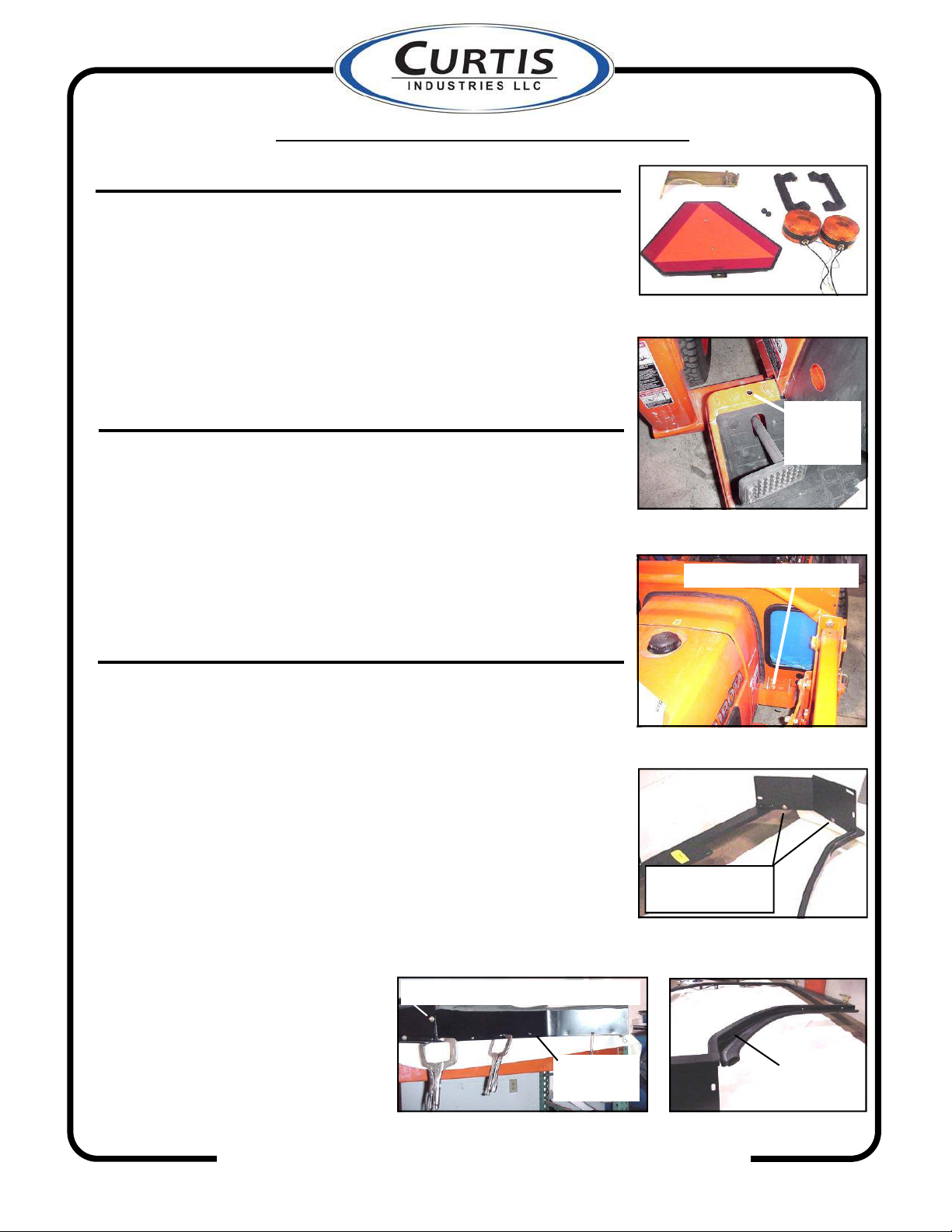
1. VEHICLE PREP. (see Fig. 1)
1.1 Remove grab handles and rear lights from left and right fenders.
1.2 Remove SMV sign and mounting bracket from roll bar.
NOTE: Leave roll bar bolt temporarily uninstalled.
1.3 For the following nine models only: 1700, 2100, 2400, 2410,
7300, 7500, 7410, 7510, and 7610, remove plastic plugs hold-
ing floor mat down in the rear corners. Also see Fig. 18 on page
6 which shows that 5/16” carriage bolts will eventually be in-
stalled in location B. Drill these two small plug holes out to
11/32” diameter at this time.
2. COWL
2.1 Per Fig. 2, transfer the hole up through the sheetmetal of the
floorboard pan using the existing hole in the front mount brack-
et as a guide. NOTE: this front mount bracket is underneath the
sheetmetal that is shown in Fig. 2. Drill a 7/16” hole from the
bottom of the vehicle upwards. Repeat for right side.
2.2 Position the cowl over the hood of the vehicle. See Fig. 3.
2.3 Loosely install 3/8” x 1-1/4” hex head bolts, steel washers, and
locknuts through the flange on the bottom of the cowl and into
the floorboard holes drilled in step 2.1.
3. FRAME PREPARATION
3.1 Remove doors from side frames by opening and lifting up off
of pin hinges.
3.2 Place the left side frame on a soft, clean surface. Install the left
floorboard extension (as shown in Fig. 4) using two 5/16-18 x
3/4” carriage bolts.
3.3 The following models use contour (A) shown in Fig. 5: B1700,
B2100, B2400, B2410, B7300, B7500, B7410, B7510, and
B7610. See page 9 for a picture of (A) & (B). Fig 6 shows con-
tour (B) required for use on the following three models: 2710,
2910, and 7800. Apply 39” long pieces of 1/2” weatherseal to
the frame tube surfaces that the contours will be fastened to.
NOTE: self adhesive backed weatherseal should be applied
to a clean, dry surface at room temperature. Clamp the ap-
propriate contour to the side frame and fasten with the supplied
self-tapping screws. On tractors
using contour (A) shown in Fig.
5, attach the contour to the floor-
board extension with a 3/4”
long carriage bolt.
3.4 Repeat steps 3.2 and 3.3 for
right side frame.
CABS/BLADES/ SPREADERS/ACCESSORIES
p. 3 of 10
Fig. 1
Fig. 4
Fig. 3
head of 3/8” hex head bolt
Fig. 2
transfer
from
bottom up
carriage bolt heads
on this upper side
Fig. 6
Fig. 5
5/16” locknut underneath floorboard
fender
contour (B)
fender
contour (A)

KUBOTA B SERIES PHASE II HARD & SOFT SIDE CABS
4. UNITIZED SIDE FRAMES
4.1 Have an assistant help position right side frame onto tractor and
cowl and hold in position. See Fig. 7. Note: The flange on the
bottom of the cowl goes on top of the floorboard extension.
See Fig. 8.
4.2 Attach top flange of cowl to frame tab with 3/4” long carriage
bolt. Attach bottom flange of cowl to floor board extension
with 3/4” long carriage bolt as well.
4.3 Install 3/4” long allen head bolts through three holes in front of
cowl into threaded inserts in side frame. Reminder: use plas-
tic washers on all exterior fasteners.
4.4 Repeat steps 4.1 through 4.3 for right side frame.
5. WINDSHIELD SUPPORT
5.1 Install the windshield support to the side frames (see Fig. 9)
with 3/4” long allen head bolts through the bottom two corner
holes and into the mounting tabs on the side frames. NOTE: the
top four holes of the windshield support will receive hardware
during roof installation.
6. HARD SIDED REAR PANEL ASSEMBLY
(Optional on Soft Sided Cabs)
6.1 Install left and right legs to rear panel with six 3/4” long car-
riage bolts. Align edges of panels and tighten hardware. See
Figure 10.
7. ROLL BAR BRACKET & REAR LEG
7.1 Install roll bar brackets to the roll bar paying careful attention
to the orientation shown in the pictures for the various tractor
models. See Fig. 11 for the following three models: 2710,
2910, and 7800. On these three models, the roll bar brackets
mount to the inside of the roll bar and the slots for attaching to
the rear legs are below the roll bar bolts. See Fig. 12 on the
next page for the following nine models: 1700, 2100, 2400,
2410, 7300, 7500, 7410, 7510, and 7610. On these nine mod-
els, the roll bar brackets mount to the outside of the roll bar and
the slots for attaching to the rear legs are above the roll bar
bolts. IMPORTANT: Do not reuse the flat washers from the
roll bar mounting bolts. Install with lock washers only and
torque to 180 foot/pounds.
CABS/BLADES/ SPREADERS/ACCESSORIES
p. 4 of 10
Fig. 7
Fig. 8
Fig. 9
Fig. 10
Fig. 11
inside edge
of roll bar
cowl flange on top of
floorboard extension
windshield
support
lock
washers

KUBOTA B SERIES PHASE II HARD & SOFT SIDE CABS
7. ROLL BAR BRACKET & REAR LEG (cont’d.)
7.2 Place the left and right rear legs, or rear panel assembly, on the
tractor. Install to side frames with 3/4” long allen head bolts in
the middle holes. Install the light brackets to the bottom holes
with 3/4” long allen head bolts as well. NOTE: the top holes
will receive hardware during roof installation.
7.3 On the following nine models: 1700, 2100, 2400, 2410, 7300,
7500, 7410, 7510, and 7610, bolt rear legs to fender contours
with 3/4” long allen head screws and plastic washers as shown
in Fig. 13. These holes are not used on any other models.
DO NOT DRILL FENDERS ON ANY TRACTOR!
8. WINDSHIELD
8.1 Install 3/4” thick spacers from hardware box onto windshield
hinges and insert flat head bolts. See Fig. 14. Have an assistant
help lift the windshield in to place and install flat washers and
locknuts. Attach windshield latches to windshield latch receiv-
ers on the cowl by squeezing tabs to retract spring loaded pins.
See Fig. 15. Lift up on bottom of windshield while closing
latches. Check alignment of windshield with side frames and
tighten hinge hardware. NOTE: Hinges are plastic com-
ponents. Do not over tighten hardware. Torque to 7
foot/pounds max.
9. ROOF
9.1 With assistance, place the roof on top of the cab. Fasten roof to
back of unitized side frames with two 1” long allen head
screws through the corners of the rear roof flange and rear legs
and into the threaded inserts in the side frame. Snug these two
bolts up. NOTE: the top of the rear legs are to be in between
the rear flange of the roof and the back of the side frames.
Ref.: Fig. 16 shows a hard rear panel assembly being installed.
Install 1” long allen head bolts into front two corner holes in
roof and bolt to unitized frame tabs with locknuts. Reminder:
use plastic washers under the heads of all exterior fasteners.
9.2 Complete the roof installation using 3/4” long allen head bolts
and plastic washers in the remaining roof holes. NOTE: on soft
sided cabs, the three middle slots on the rear flange of the roof
do get used.
CABS/BLADES/ SPREADERS/ACCESSORIES
p. 5 of 10
Fig. 12
Fig. 13
Fig. 14
Fig. 15
Fig. 16
outside edge
of roll bar
head of carriage bolt
light bracket
spacer
latch receiver

KUBOTA B SERIES PHASE II HARD & SOFT SIDE CABS
10. FINISHING TOUCHES
10.1 Have an assistant help lift up the back of the cab to get the roof
level and tighten the roll bar bracket bolts.
10.2 Tighten the remaining bolts aligning the edges of the panels
with the edges of the side frames as appropriate. Install plastic
nut covers on all exposed locknuts on the interior of the cab.
10.3 On the following three models: 2710, 2910, and 7800, use the
slots in the back of the floorboard extensions (Fig. 17; location
A) as a guide to drill an 11/32” dia. hole in the tractor floor-
board. Install a 1” long carriage bolt in the slot at location A
and tighten. NOTE: the slot next to location A is not used on
these three models. On the following nine models: 1700,
2100, 2400, 2410, 7300, 7500, 7410, 7510, and 7610, install a
1” long carriage bolt in the slot at location B and tighten. See
Fig. 18. NOTE: location B was previously drilled out in VEHI-
CLE PREP step 1.3.
10.4 If tractor has a loader, install the pocket type vinyl filler to the
inside of the loader valve cutout with velcro as shown in Fig.
19. See page 9 for the pocket type vinyl filler versus the flat
vinyl filler. NOTE: adhesive backed velcro should be ap-
plied to a clean, dry surface at room temperature. If there is
not a loader, install the flat vinyl filler over the cutout in the
cowl by attaching with velcro to the inside of the cowl.
10.5 If installing a soft side rear curtain, snap the curtain to the roof
in four places and to the bottom of the rear legs two places per
side. Apply the supplied hook velcro to the long, vertical,
inside edges of the rear legs, to the inside fender contours, and
to the top of the seat belt support bar as needed. See Fig. 20.
10.6 If installing a hard rear panel, velcro the black rubber, rear
filler to the lower rear legs as shown in Fig. 23 by applying
hook velcro to the vehicle as necessary.
CABS/BLADES/ SPREADERS/ACCESSORIES
location A
p. 6 of 10
Fig. 17
Fig. 18
Fig. 20
location B
Fig. 21
left filler
Fig. 19
filler
Fig. 22Fig. 23
right filler
rear filler
velcro

KUBOTA B SERIES PHASE II HARD & SOFT SIDE CABS
10. FINISHING TOUCHES (cont’d.)
10.7 For cabs with hard rear panel only. The under seat, black
rubber, fillers are supplied “as is” to fit the following three
models: 2710, 2910, and 7800. To fit the following nine mod-
els: 1700, 2100, 2400, 2410, 7300, 7500, 7410, 7510, and
7610, modifications need to be made per Figures 24 and 25.
NOTE: the long white lines shown on the rubber represent the
cuts to be made. The right, filler (shown in Fig. 24) will re-
quire two cuts. The cut shown on the left is to be 4” long start-
ing at the middle of the rectangular slot and going straight up.
The cut on the right is to remove the entire right side as shown
(ref.: 2 3/4” wide all the way from the relief slot and straight
down). Discard the scrap piece cut off on the right side. The
left, filler (shown in Fig. 25) requires one cut as shown (ref.:
2 1/4” wide). Discard the 2 1/4” wide scrap piece cut off the
right side.
10.8 For cabs with hard rear panel only. Apply the supplied hook
velcro to the vehicle as necessary. The left side of the seat will
require three pieces. One piece on each side of the seat belt
bracket, and one piece towards the front of the seat (long
enough so that it climbs up the inside of the fender contour for
a few inches). Repeat for the right side. Install the fillers to the
newly applied hook velcro. Fig. 22 on the previous page
shows the right filler installed. Fig. 21 on the previous page
shows the left filler installed.
10.9 Install doors onto side frames by sliding back onto pin hinges.
On hard sided doors, install the supplied gas springs as shown
in Fig. 27 (with the piston end towards the door). On soft sided
doors, install the wire cable stop as shown in Fig. 26. Use
5/16” hex head bolts, washers, and locknuts. WARNING:
DO NOT ATTEMPT TO INSTALL GAS SPRINGS ON
SOFT SIDE DOORS. DAMAGE TO THE DOOR WILL
RESULT.
10.10 Reconnect the rear lights that were removed in VEHICLE
PREP step 1.1. Use the wire extensions provided and mount
the lights to the light brackets shown in Fig. 12 on page 5.
10.11 Install wiper motor and/or any other optional accessories
according to the instructions included with those kits.
CABS/BLADES/ SPREADERS/ACCESSORIES
p. 7 of 10
Fig. 24
Fig. 25
Fig. 26
Fig. 27
cut
lines
cut
line
wire
cable
piston end of
gas spring

KUBOTA B SERIES PHASE II HARD & SOFT SIDE CABS
CARE & MAINTENANCE INSTRUCTIONS
Check and tighten hardware after 40 hours of operation.
Periodically inspect and tighten hardware for the remainder
of the unit’s life.
Wash the painted surfaces of the unit with commercial
automotive cleaning products.
Clean windows with glass cleaner.
Vinyl components should be washed with a mild solution
of warm soapy water.
Clear vinyl can be easily scratched. Be careful cleaning frost
or snow from windows. Do not roll curtains in cold weather.
The windows become stiff and may crack. Keep windows clean.
CABS/BLADES/ SPREADERS/ACCESSORIES
p. 8 of 10

* 2 1/2" FLAT SIDE BULB
QTY. P/N
MOUNTS
REAR LIGHT
CABS/BLADES/SPREADERS/ACCESSORIES
QTY. P/N
* 7/16" HEYCO
* IN HOUSE APPLICATIONS
(MIDDLE)
* GRIT PAPER
* ARCH PSA
(UNDERNEATH)
COWL
ROLL BAR
BRACKETS
FLOORBOARD
EXTENSIONS
UNITIZED SIDE
FRAMES HARD SIDE
* HINGE PIN
& HINGE
PLATES
LH, RH
* 5/16-18
1 KB17AS-09R
1 KB17AS-09L
QTY. P/N
1 KB17-17L
1 KB17-17R
QTY. P/N
RIGHT
LEFT
* BALL STUD
(7/SIDE)
INSERTS
* LATCH PIN
LEFT
RIGHT
LABEL
* HINGE
SLEEVES
(INSIDE)
* HEATER
DOORS
HARD
* WINDSHIELD LATCH
QTY. P/N
1 KB17-05
QTY. P/N
1 KB17-03R
1 KB17-03L
* 1" FLAT BULB
MOUNTS
RIGHT
LEFT
* 1-1/8" HEYCO PLUGS
SEAL (INSIDE)
* 1/2" WEATHER
(L & R SIDES)
RIGHT
LEFT
p. 9 of 10
QTY. P/N
QTY. P/N
QTY. P/N
1 KB17-13
QTY. P/N
RIGHT
* 1" HEYCO
HANDLE
LATCH
* GRAB
* OUTSIDE
* 5/8 SIDE BULB
HANDLE
* DOOR
PLUG
1 KB17AS-07R
1 KB17AS-07L
RIGHT
LEFT
STUD
* BALL
RUBBER FILLERS
SIDE
LEFT
FLAT RECTANGULAR
RUBBER FILLER
REAR
VINYL FILLER
* DECALS (INSIDE)
(SERIAL #, OPTIONS,
1 KB17-08
QTY. P/N
(L & R SIDES)
* 1/2" WEATHER
SEAL (INSIDE)
SEAL (INSIDE)
* 1/2" WEATHER
PLUGS
& R.O.P.S.)
WINDSHIELD
SUPPORT
2 KB17-04
RIGHT
REAR
LEGS
RIGHT
LEFT
VINYL FILLER
POCKET TYPE
QTY. P/N
1 KB17-16R
1 KB17-16L
1 KB17-15
1 KB17-14
CONTOUR (B)
QTY. P/N
* 1" FLAT BULB
LEFT
SEAL (INSIDE)
* 1/2" WEATHER
1 KB17-10R
1 KB17-10L
FENDER
(CUT AND OVERLAPPED
1 KB17-12L
1 KB17-12R
AT BENDS)
LEFT
RIGHT
KUBOTA B SERIES PHASE II HARD SIDED CAB PARTS LIST (p/n 1KB17AS1)
WINDSHIELD
QTY. P/N
* LATCHES
ROOF
* HEADLINER
QTY. P/N
* REFLECTORS
* LOGO
* TRIM-LOK
3 SIDES
1 KB17-01
QTY. P/N
1 KB17-06
18" x 20" GLASS
INDUSTRIES, LLC.
SIDE
1/4" GRIP
BULB
SEAM BULB
* HINGES
* 5/8"
1 KB17-02
PLUGS
HEYCO
(5/16" & 5/8")
REAR PANEL
HARD CONTOUR (A)
QTY. P/N
FENDER
1 KB17-11L
1 KB17-11R
LEFT
RIGHT

(CUT AND OVERLAPPED
* 2 1/2" FLAT SIDE BULB
QTY. P/N
1 KB17-18
CURTAIN
REAR
CONTOUR (A)
FENDER
LEFT 1 KB17-11L
1 KB17-11R
AT BENDS)
CABS/BLADES/SPREADERS/ACCESSORIES
FLAT RECTANGULAR
QTY. P/N
* SNAPS (2/SIDE)
(INSIDE)
EXTENSIONS
FLOORBOARD
* IN HOUSE APPLICATIONS
1 KB17SS-09L
1 KB17SS-09R
(L & R SIDES)
* 1/2" WEATHER
SEAL (INSIDE)
* 1-1/8" HEYCO PLUGS
SLEEVES
* HINGE
LABEL
* HEATER
(INSIDE)
QTY. P/NFRAMES SOFT SIDE
& HINGE
PLATES
UNITIZED SIDE
* 5/16-18
INSERTS
(7/SIDE)
* HINGE PIN
LH, RH
* LATCH PIN
LEFT
RIGHT
QTY. P/N
QTY. P/N
* 1" FLAT BULB
COWL
BRACKETS
ROLL BAR
1 KB17-05
* WINDSHIELD LATCH
MOUNTS
1 KB17-03R
1 KB17-03LLEFT
RIGHT
QTY. P/N
HANDLE
* 5/8 SIDE BULB
* OUTSIDE
W/ 1/4" GRIP
SOFT
DOORS
RIGHT
LEFT
LATCH
HANDLE
* GRAB
* DOOR
1 KB17SS-07L
1 KB17SS-07R
VINYL FILLER
SEAL (INSIDE)
WINDSHIELD
SUPPORT
* 1/2" WEATHER
QTY. P/N
* 7/16" HEYCO
PLUGS
MOUNTS
REAR LIGHT
1 KB17-08
(SERIAL #, OPTIONS,
& R.O.P.S.)
* DECALS (INSIDE)
* 1/2" WEATHER
(L & R SIDES)
SEAL (INSIDE)
2 KB17-04
QTY. P/N
p. 10 of 10
RIGHT
QTY. P/N
QTY. P/N
QTY. P/N
1 KB17-17R
1 KB17-17LLEFT
RIGHT
* GRIT PAPER
* ARCH PSA
(UNDERNEATH)
(MIDDLE)
1 KB17-13
VINYL FILLER
POCKET TYPE
1 KB17-10L
1 KB17-10R
QTY. P/N
RIGHT
LEFT
RIGHT
LEFT
LEGS
REAR
* 1/2" WEATHER
SEAL (INSIDE)
* 1" FLAT BULB
CONTOUR (B)
FENDER
LEFT
1 KB17-14
1 KB17-12L
1 KB17-12R
KUBOTA B SERIES PHASE II SOFT SIDED CAB PARTS LIST (p/n 1KB17SS1)
INDUSTRIES, LLC.
(INSIDE)
* SNAPS (4)
* REFLECTORS
QTY. P/N
* HEADLINER
ROOF
* TRIM-LOK
3 SIDES
* LOGO
1 KB17-01A
QTY. P/N
* HINGES
* LATCHES
WINDSHIELD
1/4" GRIP
* 5/8"
BULB
SIDE
SEAM BULB
1 KB17-02 RIGHT
QTY. P/N
This manual suits for next models
1
Table of contents
Other Curtis Tractor Accessories manuals
Popular Tractor Accessories manuals by other brands

Spearhead
Spearhead TWIGA 500 Handbook

Grouser Products
Grouser Products Ag 240I Owner's manual & parts book

Erskine Attachments
Erskine Attachments 60 Operator's manual

Frontier
Frontier BOX BLADES Series Operator's manual

Black Widow
Black Widow ATV-TINE-2145 instructions

MK Martin
MK Martin MK Series Operator's & parts manual