Curtis 1MA5100PR Operating instructions

1 of 25
INSTALLATION & OWNER’S MANUAL
Mahindra 5100
Cab with Heater (p/n: 1MA5100PR)
fits tractor models: 5145 & 5155 (Model Year 2022-)
(*=Not including accessories)
Available Options:
1. Front LED Work Lights (P/N: 9LEDW4)
2. Rear LED Work Lights (P/N: 9LEDW3)
3. Strobe Light (P/N: 9LEDS2)
4. Dome Light (P/N: 9LEDD14)
5. Side View Mirrors (P/N: 9PM5)
6. Rear View Mirror (P/N: 9PM3)`
7. Rear Wiper (P/N: 9PWK8512F9-11A)
8. Switch Panel (9PSF1)
9. Sure Step Kit (9CST)
Approximate Installation Time *
Experienced Dealer Technician – 3.5 Hours
Average Dealer Technician – 4.5 Hours
Do-It-Yourself – 5.5 Hours
Approximate Product Specifications
Floorboard to Roof Height: 63.5 inches
Weight: 385 lbs.
Cab Width: 64 inches
Rev. A, 01/25/2023
P/N: IM-1MA5100PR
The contents of this envelope are the property of the owner. Leave with the owner when installation is complete.
Shown with optional work lights.
While this cab kit was designed to fit on the vehicle(s) listed above, manufacturing tolerances and vehicle
assembly may affect cab fitment. It is the responsibility of the cab installer to check all vehicle pedals and
levers for full functionality and, as required, adjust the cab fitment to prevent any interference of the cab
components with the travel of pedals or levers.

2 of 25
TABLE OF CONTENTS
WARNINGS, TIPS, & REQUIRED TOOLS...................................................... 3
CAB INSTALLATION.................................................................................. 4-17
CAB FEATURES & OPERATION.................................................................. 18
CARE AND MAINTENANCE......................................................................... 17
CAB FEATURES........................................................................................... 18
SERVICE PARTS .................................................................................... 19-22
OPTIONAL ACCESSORIES ......................................................................... 23
TORQUE SPECIFICATIONS ................................................................... 24-25

3 of 25
Curtis cabs feature an assembly of parts designed for your vehicle which require adjustment
and alignment of components to accommodate vehicle variations and provide proper weather
protection. For accurate installation, proper operation, and years of satisfaction, please read
and understand the installation and owner’s manual fully prior to installing the cab.
From all of us at Curtis, we thank you for choosing our product.
HELPFUL HINTS:
•Refer to parts diagram found in the service parts section of this manual to help identify parts during the assembly process.
•To assist with the cab installation, leave all fasteners loose for later adjustment unless otherwise specified.
•Read and understand all instructions before beginning.
•Apply a silicone sealant to seal any minor gaps that may occur due to vehicle variations.
•Use caution to avoid damaging the factory installed threaded inserts or weld nuts. Begin the thread engagement by hand to
avoid or correct potential cross threading.
•Make sure the areas where the supplied self-adhesive hook Velcro and seals will be applied are clean, dry, and at room
temperature for best adhesion.
•Before installing parts with factory installed rubber, make sure the rubber is fully installed onto the parts for proper fit and
sealing.
driver and passenger.
Curtis accessory weights are listed in product
add additional weight to the base vehicle. All
Curtis Cabs, blades and general accessories
ADDED
WEIGHT
brochures. Deduct the accessory's total weight
from the vehicle's rated capacity and never
exceed the vehicle's rated capacity including
Exposure to Carbon Monoxide
can Cause illness, serious injury or
death. Never operate vehicle if suspicious of Carbon Monox-
ide. Inspect exhaust system for leaks monthly. Leaks can
result from loose connections, corrosion, cracks or other
damage to the exhaust manifold. If leaks are found, repair or
replace exhaust system. Do not use vehicle until repair or
replacement is complete.
•Set of Standard and Metric Sockets (Deep & Shallow, 3/8” Drive)
•3/8” Drive Ratchet with Extension
•Torque Wrench
•Set of Standard and Metric Open-End Wrenches
•Set of Standard and Metric Allen Wrenches
•#2 and #3 Phillips Head Screwdrivers
•Flat Head Screw Driver
•Body Clip Removal Tool or Needle Nose Pliers
•Coolant Drain Pan
•Pipe Dope (Not Teflon Tape)
•Drill/Driver
•#2 and #3 Phillips Head Bit
•#2 Square Drive bit
•Utility Knife
•Pair of Scissors
•Shears
•Grease
•Silicone Sealant
•Tape Measure
•China Marker or other Non-Permanent Marker
•Snips
•Plastic Putty Knife
•Isopropyl Alcohol
WARNINGS, TIPS, & REQUIRED TOOLS
TOOLS REQUIRED:
GENERAL INFORMATION BEFORE YOU START
California Health and Safety Proposition 65 Warning: This product may contain chemi-
cals known to the state of California to cause cancer and birth defects or other reproductive harm.

CAB INSTALLATION
4 of 25
STEP 1: (VEHICLE PREP)
1.1 Remove the negative battery terminal with the cam
lever. Remove and set aside the nut from the positive
battery terminal stud. See Figure 1.1.
Tools required
10mm Wrench or Socket
1.2 Remove and set aside the toolbox and its fasteners.
See figure 1.2.
Tools required
17mm Wrench or Shallow Socket
1.3 Remove and discard the fender mounted grab handle
along with its fasteners. See Figure 1.3.
Tools required
12mm Wrench or Socket
1.4 Remove and discard the shin guards and their mounting
fasteners found on either side of the tractor at the front
of the floorboard. See Figure 1.4.
Tools required
12mm Wrench and Socket
1.5 Free up and fold forward the rear portion of the
floorboard mat. Expose the PTO lever guide plate bolts
and area around the gas pedal. See Figure 1.5. NOTE:
It may be necessary to remove the loader control
cable cover plate from the right fender to lift the
floormat.
1.6 Remove and set aside the PTO lever guide plate and
(4) bolts securing it. See Figure 1.5.
Tools required
12mm Wrench or Socket
Fig. 1.3 (Fender Mounted Grab Handle)
Fig. 1.4 (Shin Guard - Right Side Shown)
Fig. 1.1 (Battery Terminals)
Fig. 1.2 (Tool Box)
Positive Battery Terminal Stud
Grab Handle
Shin Guard
Fig. 1.5 (Floorboard Mat, left)
Tool Box

CAB INSTALLATION
5 of 25
STEP 2: (CAB SEALING)
2.1 Wipe underside of the previously removed PTO lever
guide plate with Isopropyl alcohol. Once dry, adhere the
supplied .2” wide x .15” tall sealing bulb around the guide,
between the welded-on standoffs. See Figure 2.1.
2.2 Reinstall the PTO lever guide on top of the vehicle’s
floorboard sandwiching the supplied rubber seal using the
(4) fasteners removed in step 1.6 on the previous page.
See Figure 2.2.
Tools required
12mm Wrench or Socket
2.3 Position the (2) 4” long supplied flex brushes to either side
of the forward shuttle pedal, centered along the pedal’s
travel. Secure each brush with (2) self-drilling screws
provided. See Figure 2.3.
Hardware Used Qty
#10 Self-Drilling Screw 4
Tools required
#2 Square Drive Bit & Driver
**Caution: Check for smooth and unobstructed pedal
operation prior to placing machine into service.**
2.4 Wipe area around the fender mounted grab handle
fastener holes removed in step 1.3 on the previous page
with Isopropyl alcohol. Once dry, adhere a supplied red
circular decal over each hole.
2.5 With the seat in the forward most position, using Isopropyl
alcohol, wipe the top of the cross brace and up each
fender at approx. 30 degrees from vertical. Once dry,
adhere the supplied 1/2” x 916” foam weather seal as
shown in Figure 2.5.
2.6 Cut supplied adhesive Velcro to fit around 3-point lever
seal, leaving release paper in place. Wipe area directly
around the 3-point raise and lower lever with Isopropyl
alcohol. Once dry, position the supplied 3-point lever seal
around lever. Fit in place, remove release paper from
adhesive Velcro and adhere in place. See Figure 2.6.
Fig. 2.2 (PTO Lever Guide & Seal)
Fig. 2.1 (Guide Plate with Sealing Bulb Adhered)
Fig. 2.3 (Flex Brush Orientation)
Fig. 2.5 (Foam Weather Seal Orientation)
Fig. 2.6 (3-Point Raise & Lower Lever Seal)
Foam Weather Seal

CAB INSTALLATION
6 of 25
STEP 3: (FLOORBOARD BRACKETS)
3.1 Remove the left side lower fender bolt and reinstall
finger tight only with the supplied floorboard-to-fender
bracket as shown in Figure 3.1.
3.2 Repeat step 3.1 on the right side of the vehicle.
Tools required
12mm Wrench and Socket
Fig. 5.1 (Rear Panel to Toolbox Bracket)
Fig. 6.1 (Lower Rear Panel to Rear Mount Bracket)
STEP 6: (LOWER REAR PANEL)
6.1 Have an assistant, while kneeling in the tractor seat,
locate the lower rear panel between the fenders and
aligning the front of it with the fender cross brace. Push
down from the top, compressing the sealing bulb on the
lower rear panel and the foam weather seal previously
installed to the vehicle. Align slots in brackets and fasten
using the provided hardware. See Figure 6.1.
Hardware Used Qty
5/16-18 x 3/4” Hex Head Screw 2
Tools required
1/2” Socket or Wrench
If necessary, adjust assembly to be parallel with cross
brace and fully compress the seals on the fender cross
brace and retighten mounting bracket hardware.
Fig. 4.1 (Toolbox to Rear Panel Bracket)
Fig. 3.1 (Floorboard-to-Fender Bracket Orientation)
Lower Fender Bolt
Floorboard to Fender Bracket
STEP 4: (TOOLBOX TO REAR PANEL
BRACKET)
4.1 Reinstall the toolbox using the fasteners removed in step
1.2. Sandwich the supplied toolbox to rear panel bracket
between the toolbox and the OEM toolbox mount. Center
supplied bracket in slots and snug fasteners. See Figure
4.1.
Tools required
17mm Wrench or Shallow Socket
Toolbox to Rear Panel Bracket
STEP 5: (LOWER REAR PANEL PRE-
ASSEMBLY)
5.1 Locate the lower rear panel and rear panel to toolbox
bracket. Keeping the slots centered, snug components
together. See Figure 5.1.
Hardware Used Qty
5/16-18 x 3/4” Hex Head Screw 2
5/16” x 1” OD Fender Washer 2
5/16-18 Hex Lock Nut 2
Tools required
1/2” Socket & Wrench
5/16-18 Screw
5/16” Lock Nut
5/16-18 Screw
5/16” Fender Washer

CAB INSTALLATION
7 of 25
STEP 7: (SIDE FRAMES - REAR LEGS)
7.1 With assistance, remove the pre-assembled left door
from the left side frame and set aside. Do not lose the
brass washers on the hinge pins.
7.2 Locate the left side rear leg and align lower edge of rear
leg with the lower edge of the side frame’s contour filler.
Secure rear leg to side frame with the supplied hardware
ensuring there is no gap at “A”. See figure 7.2.
Hardware Used Qty
5/16-18 x 3/4” Hex Head Screw 5
Tools required
1/2” Wrench or Socket
7.3 Install 1” bulb rubber to the side frame assembly; starting
at the floorboard, continuing on to the rear leg as shown
in Figure 7.3. Note: Ensure the bulb rubber’s grip is
fully seated along the entire length and cut to length.
7.4 With an assistant, position the side frame assembly up
onto the fender and rotate the front in. Install the front
side frame fasteners finger tight at this time. See Figure
7.4.
Hardware Used Qty
5/16-18 Hex Lock Nut 2
5/16-18 x 1” Hex Head Screw 2
Tools required
1/2” Wrench and Socket
7.5 Secure the rear portion of the side frame assembly finger
tight only. Side frame can be shifted forward or back
to help sealing at fender. See Figure 7.5.
Hardware Used Qty
5/16-18 x 3/4” Hex Head Screw 3
5/16-18 Hex Lock Nut 3
Tools required
1/2” Wrench and Socket
7.6 Repeat steps 7.1 thru 7.5 on the right side of tractor. See
Figure 7.6.
Fig. 7.2 (Side Frame to Rear Leg Orientation)
Fig. 7.4 (Front Side Frame Fasteners)
Fig. 7.3 (Side Frame - Rear Leg Sealing Bulb)
Fig. 7.5 (Rear Side Frame Fasteners)
Fig. 7.6 (Right Side Frame Fasteners)
Note: Right Side Frame’s
Floorboard Swings Into
This Opening. 5/16-18 Screw
5/16” Fender Washer
5/16” Lock Nut
Align Edges
Start Here On
Floorboard
Terminate Here
On Rear Leg
5/16” Lock Nuts
5/16-18 X 1” Screws
“A”

CAB INSTALLATION
8 of 25
STEP 9: (COWL)
9.1 With an assistant, carefully lower the cowl assembly down
into place as shown. The polycarbonate side windows
mount to the outside surface of the front legs while upper
steel portion of the cowl fastens to the inboard side of the
side frames. See Figures 9.1a & 9.1b.
Hardware Used Qty
5/16-18 x 3/4” Hex Head Screw 10
5/16” Nylon Washers 4
5/16-18 Hex Lock Nut 4
Tools required
1/2” Wrench and Socket
9.2 Install the left side cowl bracket. See figure 9.2.
Hardware Used Qty
5/16-18 x 3/4” Hex Head Screw 3
5/16” Nylon Washers 2
5/16-18 Hex Lock Nut 2
Tools required
1/2” Wrench and Socket
9.3 Repeat step 9.2 on the right side of tractor.
Fig. 8.1 (ROPS Bracket to Rear Leg Orientation)
Fig. 9.2 (Cowl Bracket Orientation)
Fig. 10.1 (Windshield Support)
STEP 8: (ROPS BRACKET & CLAMPS)
8.1 Assemble the ROPS bracket to the rear leg as shown in
Figure 8.1.
Hardware Used Qty
5/16-18 x 3/4” Hex Head Screw 2
5/16-18 Hex Lock Nut 2
Tools required
1/2” Wrench and Socket
8.2 Position the ROPS clamp around the ROPS and fasten it
to the previously installed ROPS bracket as shown in
Figure 8.1.
Hardware Used Qty
5/16-18 x 3/4” Hex Head Screw 4
5/16-18 Hex Lock Nut 4
Tools required
1/2” Wrench and Socket
8.3 Repeat steps 8.1 and 8.2 on the right side of tractor.
Fig. 9.1a & 9.1b (Cowl Fasteners)
STEP 10: (WINDSHIELD SUPPORT)
10.1 Position the windshield support across the side frames
and install the front fasteners, snug only at this time. See
Figure 10.1.
Hardware Used Qty
5/16-18 x 1” Hex Head Screw 2
5/16-18 Hex Nut 2
Tools required
1/2” Wrench and Socket
5/16-18 Screw
5/16” Nylon Washer
5/16” Lock Nut
5/16” Lock Nut
5/16-18 Screw
5/16” Lock Nut
5/16-18 Screw
5/16” Nylon Washer
5/16-18 Screw
5/16” Lock Nut
5/16-18 Screw
ROPS Bracket
ROPS Clamp

CAB INSTALLATION
9 of 25
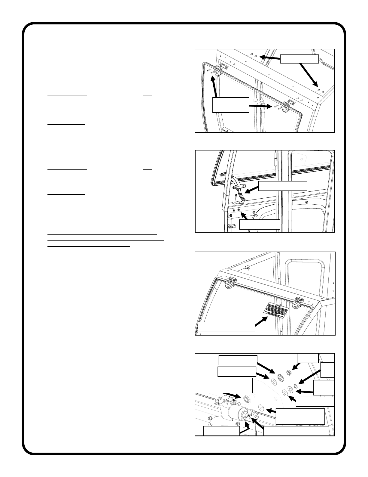
Fig. 11.1 (Attach Main Harness To Cowl)
Fig. 11.4 (Bottom shown, top similar)
STEP 11: (CAB WIRING)
11.1 Attach the main power wire harness to the top of the cowl
cross brace, about 6” from the end of the windshield
wiper motor connector, using a P-clip and hardware. The
connector end should be outside the cab with the rest of
the harness on the inside. See Figure 11.1.
Hardware Used Qty
#10-32 x 1/2” Pan Head Screw 1
#10-32 Hex lock Nut 1
Tools required
#2 Phillips Screw Driver
3/8” Wrench or Socket.
11.2 Snap in the heater switch and connect the wire harness.
11.3 Attach the harness to the under side of the cowl with the
supplied P-clamp & hardware listed below. See Figure
11.1.
Hardware Used Qty
#10-32 x 1/2” Pan Head Screw 1
#10-32 Hex lock Nut 1
Tools required
#2 Phillips Screw Driver
3/8” Wrench or Socket.
11.4 Run the wire harness down along the right side trim ring,
fastening with the (3) factory installed wire ties and
through the 11/16” hole in the right side cowl window.
See Figure 11.4.
11.5 Locate the supplied 7/16” I.D. rubber grommet. Slice the
grommet in order to wrap it over the wire harness and
then install into the 11/16” cowl hole.
11.6 Run the harness to the battery compartment on the right
side of vehicle under the floorboard. Make sure that
wires will not be cut or pinched routing to battery.
11.7 Locate the fuse harness (WH-GF). Make certain the fuse
is installed in the fuse holder. Connect the fuse harness
to the main power harness via the bullet connectors.
Install the ring terminal found on the fuse harness to the
positive battery terminal stud and secure using the nut
which was removed in step 1.1. See Figure 11.7.
11.8 Install the ring terminal of the main power wire harness to
the negative battery terminal stud. Do not reinstall the
negative battery terminal at this time. Coil the slack in
the power harness and secure with a wire tie. See Figure
11.7. Double check that the wires are not pinched or
near sharp or hot surfaces.
NOTE: At the installer’s discretion, wiring for accessories
may also be installed at this time.
Fig. 11.7 (Power Supply Connections)
P-Clamp
P-Clamps on Underside of
Cross Brace
Wire Tie

CAB INSTALLATION
10 of 25
STEP 12: (WINDSHIELD ASSMBLY)
12.1 With assistance, set the windshield up to the side
frames and secure it to the windshield support using the
hinge spacers and hardware. See Figure 12.1. Leave
hardware loose.
Hardware Used Qty
5/16-18 x 1-1/2” Flat Head Screw 4
5/16-18 Hex Lock Nut 4
Tools required
#3 Phillips screw driver
½” Wrench or Socket.
12.2 Secure the windshield latches to the side frames with
the latches open, and tighten latch hardware. See
Figure 12.2.
Hardware Used Qty
¼-20 x 5/8” Hex Head Screw 4
¼-20 Hex Lock Nut 4
Tools required
3/8” Wrench or Socket
7/16” Wrench or Socket
12.3 Close the windshield while lifting up on the bottom
edge. Tighten hinge hardware.
Caution: The windshield hinges are plastic
components. Do not overtighten the flat head
screws. Torque to 7 ft.-lbs. max.
12.4 Ensure the windshield latches function properly and the
windshield pivots open.
12.5 Remove the over-tightening caution decal from the top
of the windshield. See Figure 12.5.
Fig. 12.5 (Decal Removal)
Fig. 13.1 (Windshield Wiper Motor)
Over Tightening Decal
Hex Nut
Plastic Washer
Rubber Washer
Large Collared Bushing
(Inside)
1/4” Int. Tooth Lock Washer
Small Collared
Bushing (Inside)
Rubber Washer
Cap
Nut
Steel
Washer
Fig. 12.1 (Windshield Assembly)
5/16-18 Flat
Head Screws
5/16” Lock Nuts
Fig. 12.2 (Secure Windshield Latches)
1/4-20 x 5/8” Screws
1/4-20 Lock Nuts
STEP 13: (WINDSHIELD WIPER
MOTOR)
13.1 Mount the wiper motor to the windshield. See Figure
13.1. Make sure the wires are above the wiper motor
shaft to prevent pinching the wires when the windshield
is opened and closed, then connect to the wire harness.
NOTE: Do not install the wiper arm and blade at this time.
Once all the wiring is complete and power is restored, it
can be turned on and off to ensure that the wiper arm
will be parked in the correct position once it is attached
at a later step.
13.2 Re-check the windshield pop-out function. The wiper
motor should easily clear the cowl, but if not, loosen the
windshield hinges and raise the windshield to gain some
clearance.
1/4-20 Screw

CAB INSTALLATION
11 of 25
STEP 15: (TIGHTEN HARDWARE)
15.1 Tighten all hardware at this time, using the torque values
found on the last (2) pages of this manual.
Note: Each side frame can be pushed rearward to close any
gaps along the fender contour before tightening
hardware.
Note: Suggested tightening sequence is as follows:
Floorboards, lower rear panel, cowl, windshield
support, roof, and ROPS brackets.
Fig. 14.1 (Roof Fasteners)
STEP 14: (ROOF)
14.1 With assistance, set the roof on top of the cab. Loosely
secure with the hardware listed below. See Figures 14.1
and 14.2. Nylon washers are not used on the rear
fasteners depicted in Figure 14.2.
Hardware Used Qty
5/16-18 x 3/4” Hex Head Screw 13
5/16” Nylon Washers 11
5/16-18 Hex Lock Nut 11
Tools required
1/2” Wrenches and/or Sockets
14.2 Once all roof fasteners are started, measure the width of
the opening between rear legs. Adjust the width if
needed, to 25-1/8” - 25-3/16”. See Figure 14.2.
Fig. 14.2 (Rear Leg Opening)
25-1/8” - 25-3/16”
STEP 16: (REAR WINDOW)
16.1 Grease the hinge pins found on the left side rear leg
and slide on greased brass washers (one washer per
pin). See Figure 16.1.
16.2 Hang the rear window on the hinges.
Note: Loosen rear window hinges if adjustment is needed.
16.3 Connect the window latches to the right rear leg by
depressing the tabs on the latch and inserting into the
receivers mounted on the rear leg. Close and check the
alignment of the window. If off, check measurements
and re-align the rear legs. Tighten the hinge hardware
to 7 ft.-lbs. Verify smooth operation of the latches. Fig. 16.1 (Hang Rear Window)
Brass Washers
on Greased Pins
Snap Latches
into Right
Rear Leg
2 Places
STEP 17: (HEATER)
17.1 Attach the heater bracket to the right side frame. See
Figure 17.1. Fully tighten hardware at this time.
Hardware Used Qty
5/16-18 x 3/4” Hex Head Screw 2
Tools required
½” Socket and Extension
17.2 Attach the heater to the heater bracket by removing and
re-using the screws on the side of the heater. Tighten
hardware.
Tools needed
#2 Phillips Screw driver. Fig. 17.1 (Install Heater Bracket to Side Frame)
5/16-18 x 3/4” Screws
5/16-18 Lock Nuts
5/16” Nylon Washers5/16-18 x 3/4” Screws
5/16-18 x 3/4” Screws
And
5/16-18 Locknuts

CAB INSTALLATION
12 of 25
STEP 18: (HEATER PLUMBING)
* CAUTION * To avoid injury caused by hot engine
coolant, make sure the engine has completely
cooled down before beginning plumbing of
auxiliary heater.
18.1 Place a clean coolant drain pan under the radiator,
loosen petcock and let the coolant drain into the pan.
18.2 Once coolant is drained, remove and set aside the
upper radiator hose, side guards and air filter.
Reference the vehicle’s manual if needed. See Figure
18.2.
18.3 Skip to step 18.4 if installing on tractor with block
heater. Cut the lower radiator hose and install the
supplied T-fitting with 2 large hose clamps as shown
in figure 18.3.
18.4 Remove plug from block heater and install it on the
end of the supplied sending unit adaptor. Thread plug
into adaptor and tighten. See Figure 18.4.
18.5 Install a small nylon washer onto the other end of the
sending unit adaptor and install the hex bushing. Install
the assembly into the engine block heater with a large
nylon washer where the plug was removed. If the
sending unit adaptor does not tighten so that the port on
the side for the 3/8” NPT nipple orients as desired, then
remove it and install another nylon washer and try
again. Install the 3/8” NPT nipple into the side port of
the adaptor, using Teflon tape (not provided).
18.6 Install 3/8” block adaptor into side of previously
installed sending unit adaptor, using Teflon tape (not
provided).
18.7 Connect the supplied heater hose to the block adaptor
with a hose clamp and route over the top of the
radiator as shown in figure 18.7.
18.8 Route as shown; down right side of engine, rearward
along the OEM ridged coolant line, up and through
inboard bushing in right side cowl window, trim to
length and connect to inboard heater pipe with a hose
clamp. See Figures 18.8
Fig. 18.2 (OEM Items to be Removed)
Fig. 18.3 (Install Tee fitting)
Figure 18.4 (Block Heater Plug )
Block Heater Plug
Block Heater
Figure 18.7 (Return Line Routing)
1.0” Hose
Clamps
Shut-Off
Valve
Hose
Figure 18.8 (Return Line Routing)
1.0” Hose
Clamps
Shut-Off
Valve
Hose

CAB INSTALLATION
13 of 25
Supply line all models:
18.9 See fig. 18.9. Locate the 5/8” by-pass hose that runs
from the top of the water pump to the EGR system.
Mark the top of the hose in the center of the long
straight section where a T-fitting will be installed.
Remove spring clamps from both ends of hose and
remove hose from vehicle.
18.10 Cut the by-pass hose where marked and remove a ½“
piece at the spot where cut. Keeping the molded by-
pass hose oriented as it was before cutting, install the
provided T-fitting at the cut with 2 hose clamps
removed in step 18.9. Install the remaining heater
hose to the top of the T-fitting with hose clamp
provided. See Figure 18.10.
18.11 Feed by-pass hose assembly down through the
injectors and wiring, attach to water pump and EGR
with hose clamps provided. See Figure 18.11.
18.12 Route the hose as shown to the right side of the
engine. Follow the previously installed return hose to
the heater, passing through the remaining bushing in
the cowl. Trim to length and connect to heater with
hose clamp. See Figures 18.12a - 18.12c.
18.13 Splice the provided shut-off valve into either of the
heater hoses. Locate anywhere along the length of
the hose where there is good access, and the hose is
not transitioning through a bend.
18.14 Secure all heater hoses from moving parts and
excessive heat sources with the supplied wire ties.
Check for clearance when closing hood.
18.15 Reinstall the upper radiator hose, side guards, and air
filter.
Figure 18.9 (Mark By-Pass Hose)
Cut Mark
Figure 18.10 (By-Pass Hose w/ T-Fitting)
T-Fitting
Supplied Heater
Hose & Clamp
Figure 18.12b (Supply Line Routing)
Figure 18.12a (Supply Line Routing)
Supply Line
Fig. 18.11 (Installed By-Pass Hose Assy.)
Supply Line
Figure 18.12c (Supply Line Routing)
1.0” Hose
Clamps
Shut-Off
Valve

CAB INSTALLATION
14 of 25
STEP 19: (FINISH HEATER)
19.1 Connect the leads found on the heater to the main
power wire harness (orange to orange, red to red &
black to black).
19.2 Install the provided 8” length of 1/2” wire loom to the
heater leads.
19.3 Re-install the negative battery terminal to the battery.
19.4 Refill the cooling system. Start the tractor and inspect
coolant system for leaks.
19.5 With the tractor running, check the heater hoses and
make sure they get warm. If not, remove the heater
from its mount and let hang from the hoses as low as
possible. If the heater and hoses still do not get warm,
temporarily put a clamp on the upper radiator hose to
force coolant through the heater. Warning: To avoid
engine damage, remove the clamp as soon as heater
gets warm. Reattach heater to the bracket. Once
complete, let the engine cool, check the coolant level,
and top off coolant if required.
STEP 20: (FINISH WIPER)
20.1 Turn on the wiper motor briefly, then turn back off. This
will ensure the motor shaft is in the correct parked
position.
20.2 Pre-assemble the wiper arm and wiper blade.
20.3 Install the wiper arm onto the wiper motor so that the
wiper is approximately 55 degrees from vertical as
shown in Figure 20.3. Tighten the Set Screws.
Tools required
2.5mm Allen Wrench
20.4 Adjust the length of the wiper arm as long as possible
while still clearing the sealing rubber around the
perimeter of the windshield. Turn on the wiper to check
proper operation. Reference step 5 of the wiper
installation instructions.
Fig. 20.3 (Wiper Arm and Blade)
Set Screws

CAB INSTALLATION
15 of 25
STEP 21: (DOORS)
21.1 Check to make sure that the brass washers are still
installed on the left side hinge pins and then apply
grease to the pins.
21.2 Hang the left door on the hinge pins.
Note: If necessary, adjust the door as outlined in steps 21.3
thru 21.5.
21.3 Loosen the door hinges to allow for adjustment later.
While lifting up and forward on the door handle, line up
the door latch with the striker pin and carefully attempt
to latch. You should be able to hear 2 clicks as you
slowly engage the latch on the pin. If the latch is too far
forward or back to latch on the pin, adjust as shown.
See Figures 21.3a through 21.3c. Then retighten and
latch.
21.4 Stand back and examine the alignment of the door with
the roof and the A-pillar. You can adjust this by moving
the striker pin up or down as shown to help with
alignment. TIP: In the final step, the front of the door will
drop a small amount the first time you open it. Set the
front of the door a little bit higher so it aligns properly.
Adjust as necessary until you are happy with the
alignment. Have an assistant sit inside the cab and
once more carefully close the door like you did in step
21.3. Work with the assistant and tighten the hinge
bolts.
21.5 Open the door and check for smooth operation of the
latch. As noted in step 21.4, the door will likely drop a
little bit at the front and the striker pin will need to be
adjusted down accordingly. Also make sure the door
seal is making contact along the perimeter of the door
and the latch clicks twice when closing. If necessary,
adjust the striker in or out to achieve this.
21.6 With the door open, attach a gas strut to the ball studs
on the side frame and door. Make sure the quick
release end is on the side frame so that the gas strut
stays with the door if removed for ventilation.
21.7 Repeat steps 21.1 through 21.6 for the right door.
Fig. 21.3a (Door Hinge Adjustment)
Loosen Door
Hinges
Fig. 21.3b (Striker Pin)
Adjustment
Fig. 21.3c (Door Latch)
Adjustment

CAB INSTALLATION
16 of 25
STEP 23: (ACCESSORIES/PLUGS)
23.1 If installing accessories, please do so now. If not, use
the supplied plugs and/or fasteners to fill any exposed
holes. The roof assembly has been hidden for clarity in
fig. 23.1b. See Figures 23.1a thru 23.1c.
23.2 Optional Rear Wiper Note:
For easier wiper motor harness disconnection, cut the
main wiring harness connector off a few inches from the
end and create a jumper harness with it using bullet
connectors. Do not cut the connector off the wiper
motor.
Strip all the wires, crimp a male bullet connector onto
the ground (black) wire of the main wire harness and a
female bullet connector on the positive (red) wire.
Reverse the male and female bullet connectors on the
new jumper wire harness so that the male bullet
connector is on the positive (red) wire and the female
bullet connector is on the ground (black) wire.
STEP 22: (REPLACEMENT DECALS)
22.1 It is mandatory to install the newly supplied WARNING
decal to the outboard side of the left ROPS upright due
to the original decal being partially covered by the
ROPS bracket. See figure 22.1.
22.2 It is necessary to install the newly supplied CAUTION
decal to the inboard side of the right ROPS upright as
shown in figure 22.1.
Fig. 23.1a (Install Mirror Mounting Hole Plugs)
Rubber Grommet
Plugs
Fig. 22.1 (ROPS Decals)
Fig. 23.1b (Windshield Support Plugs)
Plastic Plugs
Fig. 23.1c (Floorboard Holes Plugged)
Install plastic rivet
typ. both sides.

CAB INSTALLATION
17 of 25
STEP 24: (FINISHING TOUCHES)
24.1 It may be necessary to roll out the right side frame’s
bulb rubber around the CAUTION decal found on the
top of the right fender. See Figure 24.1
24.2 Remove the protective film from rear leg, lower door,
and/or cowl windows if present at this time.
24.3 Due to the nature of the packaging materials used for
shipping this product, the components of the cab
system may have dust on their surfaces upon removal
from the packaging. It is recommended that after
completion of the cab installation, the cab and vehicle
are washed thoroughly to eliminate any dust or
contaminants. See the Care and Maintenance section
below for critical information on cleaning the cab.
24.4 For best seal, massage the rubber seal between the
side frames and the fenders with a putty knife, pushing
in or out, to close any gaps in the area shown in Figure
24.4. Fig. 24.1 (Right Fender - Caution Decal)
•Re-apply lubrication (preferably grease) periodically as needed to the door striker pins, door latch assemblies, and the door
hinges.
•Check and tighten hardware after 40 hours of operation. Periodically inspect and tighten hardware for the remainder of the
unit’s life.
•Wash the painted surfaces of the cab with commercial automotive cleaning products.
•Clean glass windows with glass cleaner. Note: Some windows on the cab are acrylic. DO NOT clean acrylic windows with
harsh chemicals. It will damage the plastic. Mild soap and water should be used on all acrylic windows.
CARE AND MAINTENANCE
Fig. 24.4 (Fender Seal, right side shown)

CAB INSTALLATION
18 of 25
POP-OUT WINDSHIELD
Your Mahindra 5100 cab comes equipped with a pop-out
windshield for ventilation. To open the windshield, simply lift
up on both of the pop-out latches and rotate until the latches
rest in the over-center position.
Lift-Off Doors
Venting/Removable Rear Window
Pop-Out Windshield
CAB FEATURES & OPERATION
REMOVABLE REAR WINDOW
The rear window can also be removed for added ventilation.
To remove the rear window:
1. Open both window latches and disconnect from right rear
leg with tabs on latch. Open the window taking care not
to let the window open into the ROPS or damage may
occur.
2. From outside of the cab, lift up on the rear window and
slide off the hinges. Remove the hinge washers and
store in a plastic bag.
Store the rear window in a safe location to prevent damage.
To reinstall the rear window, reinstall the hinge washers, align
the hinges with the pins and drop into place. Re-attach the
latches to the rear leg.
LIFT-OFF DOORS
For added ventilation, the doors on the Mahindra 5100 cab lift
off in seconds without tools.
To lift off:
1. Disconnect the gas strut from the side frame by sliding
the quick release lever and pulling the strut down.
2. Rotate the doors 90° to the cab and lift. Also, remove the
hinge washers and store in a plastic bag.
Store the doors in a safe location to prevent damage.

19 of 25
MAHINDRA 5100 PREMIUM CAB
SERVICE PARTS
ROOF ASSEMBLY
P/N: 8SV-101-00069
WINDSHIELD ASSEMBLY, 40” X 28.5”
P/N: 8SV-102-00042
WINDSHIELD SUPPORT
P/N: 8SV-103-00033
COWL CROSS BRACE ASSEMBLY
P/N: 8SV-113-00305
FRONT LEG, ASSEMBLY, LEFT
P/N: 8SV-104-00026-L
FRONT LEG, ASSEMBLY, RIGHT
P/N: 8SV-104-00026-R
WINDOW, FRONT LEG, LEFT
P/N: 8SV-P-00171-L
WINDOW, FRONT LEG, RIGHT
P/N: 8SV-P-00171-R
COWL ASSEMBLY
P/N: 8SV-105-00037
COWL FOAM SEAL, LEFT
P/N: 8SV-9FR-00087-L
COWL FOAM SEAL, RIGHT
P/N: 8SV-9FR-00087-R
COWL TRIM RING
QTY. 1
P/N: 8SV-SM-02395

20 of 25
DOOR ASSEMBLY, RIGHT
P/N: 8SV-107-00061-R
GLASS REAR PANEL LIFT OFF
P/N: 8SV-106-00021
SIDE FRAME ASSEMBLY, LEFT
P/N: 8SV-109-00029-L
REAR LEG ASSEMBLY, LEFT
P/N: 8SV-108-00029-L
REAR LEG ASSEMBLY, RIGHT
P/N: 8SV-108-00029-R
SIDE FRAME ASSEMBLY, RIGHT
P/N: 8SV-109-00029-R
BRACKET, FLOORBOARD TO FENDER
QTY. 1
P/N: 8SV-SM-02597
MAHINDRA 5100 PREMIUM CAB
SERVICE PARTS
DOOR ASSEMBLY, LEFT
P/N: 8SV-107-00061-L
BRACKET, COWL-FRAME
P/N: 8SV-SM-02432
DOOR SLIDER W/ RUBBER, LEFT
P/N: 8SV-9SW-00018-L
LOWER REAR PANEL ASSEMBLY
P/N: 8SV-106-00046
DOOR SLIDER W/ RUBBER, RIGHT
P/N: 8SV-9SW-00018-R
Table of contents
Other Curtis Tractor Accessories manuals
Popular Tractor Accessories manuals by other brands

Tektite
Tektite Toro GM328 Operation manual

Extreme Max
Extreme Max 5500.5094 Assembly & operating instructions

LS tractor
LS tractor LS3150-B Operator and parts manual

Homelite
Homelite LM-991013 Instructions-parts list

Maschio
Maschio ORSO RAPIDO Series Use and maintenance

Walker
Walker A10 Operator's manual