manuals.online logo
Brands
  1. Home
  2. •
  3. Brands
  4. •
  5. CyberData
  6. •
  7. Office Equipment
  8. •
  9. CyberData 011311 Manual

CyberData 011311 Manual

Quick Reference 931647B © 2019, CyberData Corporation, ALL RIGHTS RESERVED© 2019, CyberData Corporation, ALL RIGHTS RESERVED 931647B Quick Reference
Wall Mounting Options
Gang Box Mounting Options
Contacting CyberData
Backplate
Wall
Mounting
Screw (3x)
(Not Provided)
Network Cable &
for Ground Wire Connection
Pick One of Four Mounting Hole
Screw
121001A
Accessory Kit
(4 Places) on Wall
Pre Drill Holes
Ground Wire
Cutout
Slot
Entry
Cable
Closed
Slots
Cable
Two Gang Box use four
Wall Cutout
or Two Gang Box
Backplate accept
Single Gang Box
Single Gang Box use two
Backplate
Wall Cutout
121002B
Screw Accessory Kit
Mounting
Screw (3x)
(Not Provided)
Ground Wire
Any Available Mounting Hole
Ground Wire Connect to
(Not Provided)
Network Cable
Slot
Entry
Cable
Closed
Slots
Cable
Sales: (831) 373-2601 ext. 334
Support: 831-373-2601 ext. 333
Support Website: http://support.cyberdata.net/
RMA Department: (831) 373-2601 ext. 136
RMA Email: [email protected]
RMA Status: http://support.cyberdata.net/
Warranty Information: http://support.cyberdata.net/
Corporate Headquarters
CyberData Corporation
3 Justin Court
Monterey, CA 93940, USA
Phone: 831-373-2601
Fax: 831-373-4193
http://www.cyberdata.net/
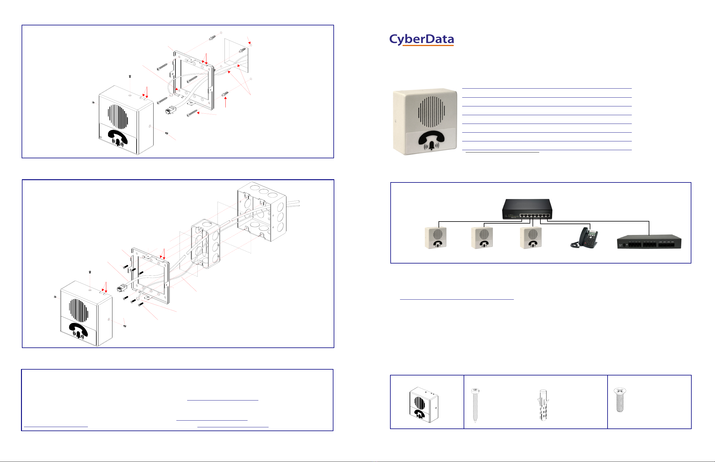
Typical System Installation
Getting Started
• Download the Operations Guide PDF file, from the Downloads tab at the following webpage:
https://www.cyberdata.net/products/011311
• Create a plan for the locations of your Office Ringers.
• WARNING: This product should be installed by a licensed electrician according to all local electrical and building codes.
• WARNING: To prevent injury, this apparatus must be securely attached to the floor/wall in accordance with the installation
instructions.
• WARNING: The PoE connector is intended for intra-building connections only and does not route to the outside plant.
• WARNING: This enclosure is not rated for any AC voltages!
Parts
Parameter Factory Default Setting
IP Addressing DHCP
IP Addressa
a. Default if there is not a DHCP server present.
10.10.10.10
Web Access Username admin
Web Access Password admin
Subnet Maska255.0.0.0
Default Gatewaya10.0.0.1
802.3af Compliant Ethernet Switch
Office Ringer IP Phone InformaCast ServerOffice Ringer Office Ringer
*More installation and mounting
options are available in the
Operations Guide.
(4) #6 x 1.25-inch
Sheet Metal Screw
(4) Plastic ribbed anchor (4) 6-32 x 0.5-inch flat
undercut Phillips machine
screw
(1) Office Ringer Assembly (1) Wall Mounting Kit (1) Gang Box Mounting Kit
The IP Endpoint Company
Installation Quick Reference
InformaCast Enabled Office Ringer
011311
© 2019, CyberData Corporation, ALL RIGHTS RESERVED 931647B Quick Reference Quick Reference 931647B © 2019, CyberData Corporation, ALL RIGHTS RESERVED
RTFM Button
Terminal Block Connections
Plug in the Network Cable and Create Service Loop
RTFM button (SW1)
When the device is operational and linked to a network,
you can use the Reset Test Function Management
(RTFM) button (SW1 [see picture]) to announce the
device’s IP address or restore the device to the factory
default settings.
To announce the device’s current IP address:
• Press and release the RTFM button within a five
second window.
Note The device will use DHCP to obtain the new IP
address (DHCP-assigned address or default to
10.10.10.10 if a DHCP server is not present).
To restore the device to factory default settings:
• Press and hold the RTFM button for longer than five
seconds until you hear the device announce that it is
restoring the factory default settings.
Alternate Power Input:
1 = +8 to +12VDC @ 1000mA Regulated Power Supply*
2 = Power Ground*
Relay Contact:
(1 A at 30 VDC for continuous loads)
3 = Relay Common
4 = Relay Normally Open Contact
5 = Sense Input
6 = Sense Ground
7 = Remote Switch "A"
8 = Remote Switch "B"
*Contacts 1 and 2 on the terminal block are only for powering the
device from a non-PoE 12VDC power source as an alternative to
Network PoE power. Use of these contacts for any other purpose will
damage the device and void the product warranty.
34
1
8
Wire (IN)
Tin Leads
Approx. 1/4” or
6mm
Terminal Block
can accept 16 AWG wire
Use a 3.17 mm (1/8-inch) flat blade
screwdriver for the terminal block screws
Two (2)
Cable Entry Slot
Two (2)
Cable Entry Slot
One (1)
Cable Entry Slot
Mounting
Screw (3x)
Create
Service Loop
Before Closing
Network
Connector
Network Cable
Backplate
Faceplate
Assembly
When Use in
Auxiliary Strobe
P/N: 011288A
(Sold Separately)
Conjunction with
Dimensions
Dimensions for Wall Mounting and One / Two Gang Box Mounting
4.53 [115.0]
4.53 [115.0]
DIMENSIONS ARE IN INCHES [MILLIMETER]
2.14 [54.3]
Dimensions Are in Inch [Millimeter]
Ø0.188 [Ø4.8]
Ø0.189 [Ø4.8]
0.910 [23.1]
3.400 [86.4]
3.280 [83.3]
3.400 [86.4]
1.820 [46.2]
Through Hole
Through Hole
82° Countersunk
= Slot Open
= Slot Close
Fits One/Two Gang Box
(6 Places)
*
*
*
3.150 [80.0]
2.895 [73.5]
(4 Places)
Cut Hole for Cable Through

Other manuals for 011311

3

This manual suits for next models

1

Popular Office Equipment manuals by other brands

HOMCOM 001-013V00 Assembly & instruction manual

HOMCOM

HOMCOM 001-013V00 Assembly & instruction manual

Ergotron Anthro-DNA Steve's Station Essential Assembly instructions

Ergotron

Ergotron Anthro-DNA Steve's Station Essential Assembly instructions

Riso CV Series user guide

Riso

Riso CV Series user guide

Fuji Xerox docucentre-v c7785 manual

Fuji Xerox

Fuji Xerox docucentre-v c7785 manual

Formax FlashCard Operator's manual

Formax

Formax FlashCard Operator's manual

Formax 6204 Series Operator's manual

Formax

Formax 6204 Series Operator's manual

OfficeSource EVH100BGG Assembly instructions

OfficeSource

OfficeSource EVH100BGG Assembly instructions

Fuji Xerox ApeosPort-V 3065 manual

Fuji Xerox

Fuji Xerox ApeosPort-V 3065 manual

IBM ELECTRONIC MULTIPLIER user manual

IBM

IBM ELECTRONIC MULTIPLIER user manual

Crate&Barrel Studio Cart Assembly instructions

Crate&Barrel

Crate&Barrel Studio Cart Assembly instructions

Mo Systeme modulbox mb3 user manual

Mo Systeme

Mo Systeme modulbox mb3 user manual

Mooreco iTeach Spider Assembly instructions

Mooreco

Mooreco iTeach Spider Assembly instructions

3-form SimpleSpec 300.44 installation manual

3-form

3-form SimpleSpec 300.44 installation manual

RIGHT ANGLE PRL installation instructions

RIGHT ANGLE

RIGHT ANGLE PRL installation instructions

Spector&Co SpecTech T1043 user manual

Spector&Co

Spector&Co SpecTech T1043 user manual

promethean ActiVote Training manual

promethean

promethean ActiVote Training manual

Oypla Office 3704 user manual

Oypla Office

Oypla Office 3704 user manual

hushoffice hushwork.sit&stand HUS-BX-016/116 Maintenance and safety manual

hushoffice

hushoffice hushwork.sit&stand HUS-BX-016/116 Maintenance and safety manual

manuals.online logo
manuals.online logoBrands
  • About & Mission
  • Contact us
  • Privacy Policy
  • Terms and Conditions

Copyright 2025 Manuals.Online. All Rights Reserved.