Quick Reference 931786C © 2023, CyberData Corporation, ALL RIGHTS RESERVED© 2023, CyberData Corporation, ALL RIGHTS RESERVED 931786C Quick Reference
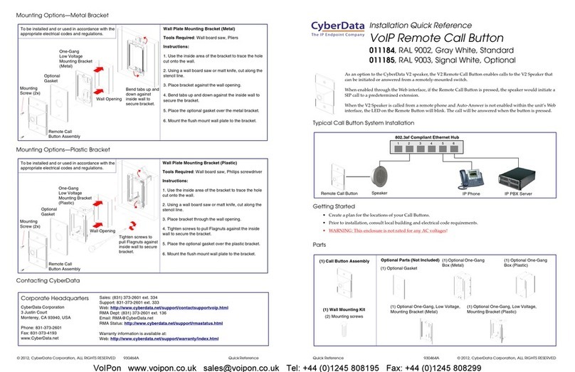
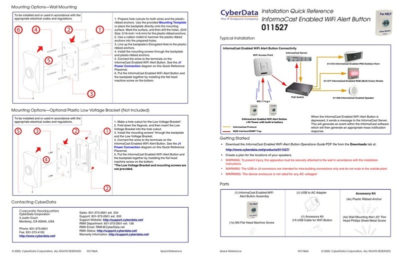
Mounting Options—Wall Mounting
Mounting Options—Optional Plastic Low Voltage Bracket (Not Included)
Contacting CyberData
To be installed and or used in accordance with the
appropriate electrical codes and regulations. 1. Prepare hole cutouts for both wires and the plastic-
ribbed anchors. Use the provided Mounting Template
or place the backplate directly onto the mounting
surface. Mark the surface, and then drill the holes. (Drill
Size: 3/16-inch / 4.8-mm) for the plastic-ribbed anchors.
2. Use a rubber mallet to hammer the plastic-ribbed
anchors into the prepared holes.
3. Line up the backplate's Elongated Hole to the plastic-
ribbed anchors.
4. Install the mounting screws through the backplate
and plastic-ribbed anchors.
5. Connect the wires to the terminals on the WiFi Alert
Button. See the J1 Power Connection diagram on this
Quick Reference Placemat.
6. Put the WiFi Alert Button and the backplate together
by installing the flat head machine screw on the bottom.
The hole pattern of the WiFi Alert Button's back plate
can be mounted on a standard gang box or low voltage
mount (pictured to the left).
1. Make a hole cutout for the Low Voltage Bracket*.
2. Fold down the flagnuts, and then insert the Low
Voltage Bracket into the hole cutout.
3. Install the mounting screws* through the backplate
and the Low Voltage Bracket.
4. Connect the wires to the terminals on the
InformaCast Enabled WiFi Alert Button. See the J1
Power Connection diagram on this Quick Reference
Placemat.
5. Put the InformaCast Enabled WiFi Alert Button and
the backplate together by Installing the flat head
machine screw on the bottom.
*The Low Voltage Bracket and mounting screws
are not provided.
To be installed and or used in accordance with the
appropriate electrical codes and regulations.
Sales: 831-373-2601 ext. 334
Support: 831-373-2601 ext. 333
Support Website: https://support.cyberdata.net/
RMA Department Contact and Status: https://support.cyberdata.net/
Warranty Information: https://support.cyberdata.net/
Corporate Headquarters
CyberData Corporation
3 Justin Court
Monterey, CA 93940, USA
Phone: 831-373-2601
Fax: 831-373-4193
https://www.cyberdata.net/
Typical Installation
Getting Started
• Download the WiFi Alert Button Operations Guide PDF file from the Downloads tab at:
https://www.cyberdata.net/products/011527/
• Create a plan for the locations of your WiFi buttons.
• WARNING: To prevent injury, this apparatus must be securely attached to the wall in accordance with the installation
instructions.
• WARNING: The device enclosure is not rated for any AC voltages!
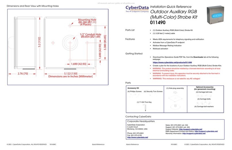
Parts
Accessory Kit
(1x) M3 Flat Head Machine Screw
(4x) Plastic Ribbed Anchor
(4x) Wall Mounting #6x1.25" Pan
Head Phillips Sheet Metal Screw
(1) USB to AC Adapter
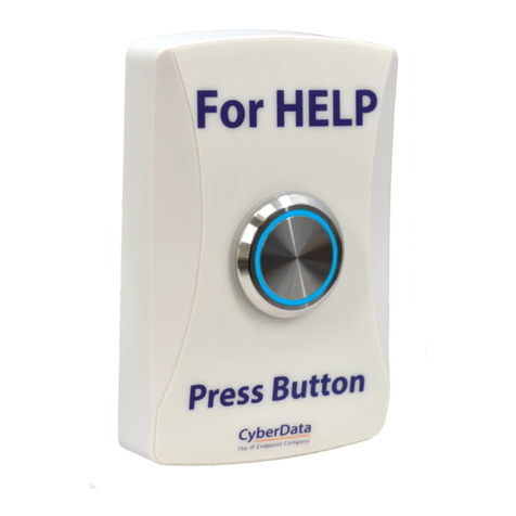
(1) WiFi Alert Button
Assembly
(1) Accessory Kit-USB
Cable Kit for Wi-Fi Button
The IP Endpoint Company
Installation Quick Reference
WiFi Alert Button
011527


