CYP CHDBT-1H3CL User manual

CHDBT-1H3CL
1×4 HDMI over HDMI and CAT5e/6/7 Splitter
Operation Manual
Operation Manual


DISCLAIMERS
The information in this manual has been carefully checked and
is believed to be accurate. Cypress Technology assumes no
responsibility for any infringements of patents or other rights of third
parties which may result from its use.
Cypress Technology assumes no responsibility for any inaccuracies
that may be contained in this document. Cypress also makes no
commitment to update or to keep current the information contained
in this document.
Cypress Technology reserves the right to make improvements to this
document and/or product at any time and without notice.
COPYRIGHT NOTICE
No part of this document may be reproduced, transmitted,
transcribed, stored in a retrieval system, or any of its part translated
into any language or computer le, in any form or by any means—
electronic, mechanical, magnetic, optical, chemical, manual, or
otherwise—without express written permission and consent from
Cypress Technology.
© Copyright 2011 by Cypress Technology.
All Rights Reserved.
Version 1.0 September 2011
TRADEMARK ACKNOWLEDGMENTS
All products or service names mentioned in this document may be
trademarks of the companies with which they are associated.

SAFETY PRECAUTIONS
Please read all instructions before attempting to unpack, install or
operate this equipment and before connecting the power supply.
Please keep the following in mind as you unpack and install this
equipment:
• Always follow basic safety precautions to reduce the risk of re,
electrical shock and injury to persons.
• To prevent re or shock hazard, do not expose the unit to rain,
moisture or install this product near water.
• Never spill liquid of any kind on or into this product.
• Never push an object of any kind into this product through any
openings or empty slots in the unit, as you may damage parts
inside the unit.
• Do not attach the power supply cabling to building surfaces.
• Use only the supplied power supply unit (PSU). Do not use the PSU
if it is damaged.
• Do not allow anything to rest on the power cabling or allow any
weight to be placed upon it or any person walk on it.
• To protect the unit from overheating, do not block any vents or
openings in the unit housing that provide ventilation and allow for
sufcient space for air to circulate around the unit.
REVISION HISTORY
VERSION NO. DATE DD/MM/YY SUMMARY OF CHANGE
RDV1 27/02/13 Preliminary Release
RDV2 13/06/13 Package Contents
RDV3 17/06/13 Dimension
RDV4 20/06/13 Add IR Cable Pin Dene
RDV5 01/07/13 IR Power
VS1 23/12/13 Updated Text & Diagrams

CONTENTS
1. Introduction............................................ 1
2. Applications........................................... 1
3. Package Contents ................................ 1
4. System Requirements............................ 1
5. Features.................................................. 2
6.1 Front Panel.........................................3
6.2 Rear Panel .........................................4
6.3 IR Cable Pin Assignment ..................5
7. Connection Diagram ............................ 6
8. Specications ........................................ 7
8.1 Technical Specications ..................7
8.2 CAT5e/6/7 Cable Specication ......8
9. Acronyms ............................................... 8

1
1. INTRODUCTION
The HDMI over HDMI and CAT5e/6/7 Splitter can split and distribute
a single HDMI input and 2-way IR control to up to three CAT5e/6/7
outputs and includes a simultaneous HDMI bypass output. It supports
resolutions up to 1080p Full HD, 4K×2K timing, 3D and multi-channel
digital audio formats (such as LPCM 7.1CH, Dolby TrueHD, Dolby Digital
Plus and DTS-HD). The HDMI bypass output can be connected to an
HDMI display or cascaded to another splitter. The three CAT5e/6/7
outputs can be connected to CAT5e/6/7 to HDMI receivers to extend
the operating distance up to 60 meters.
2. APPLICATIONS
• Household entertainment sharing and control
• Lecture room display and control
• Showroom display and control
• Meeting room presentation and control
• Classroom display and control
3. PACKAGE CONTENTS
• 1×4 HDMI over HDMI and CAT5e/6/7
• 1×IR Receiver
• 1×IR Blaster
• 24V DC Power Adaptor
• Power Cord
• Operation Manual
4. SYSTEM REQUIREMENTS
• HDMI equipped source devices, connect with HDMI cables
• HDMI equipped displays (TVs or monitors) or HDMI equipped AV
receivers, connect with HDMI cables
• Certied CAT5e/6/7 cables
• HDBaseT™ Lite Receivers (e.g. CH-506RXL or CH-514RXL)

2
5. FEATURES
• HDMI with 4K×2K resolution and 3D support, HDCP and DVI
compliant
• Simultaneous HDMI and CAT5e/6/7 outputs
• Supports data rate from 300 Mbps up to 3 Gbps
• Supports a wide range of PC resolutions from VGA to WUXGA
(RB) and HDTV resolutions up to 4K×2K (3840×2160@30 Hz and
4096×2160@24 Hz)
• Supports transmission of High Denition audio: LPCM 7.1CH, Dolby
TrueHD, Dolby Digital Plus and DTS-HD Master Audio (32 kHz~192 kHz
sample rate)
• Supports distances up to 60 meters over CAT5e/6/7 cables
• Supports selection of Standard or TV EDID settings
• Supports control of devices via 2-way IR
• 3D signal display is dependent on the TV/Display’s EDID settings
Note:
1. This system was tested with CAT6/23AWG cables, results may vary
with cables of a different specication.
2. For playback of 4K×2K HDMI source signals, a 4K×2K capable
display and High Speed HDMI cables are required.

3
6. OPERATION CONTROLS AND FUNCTIONS
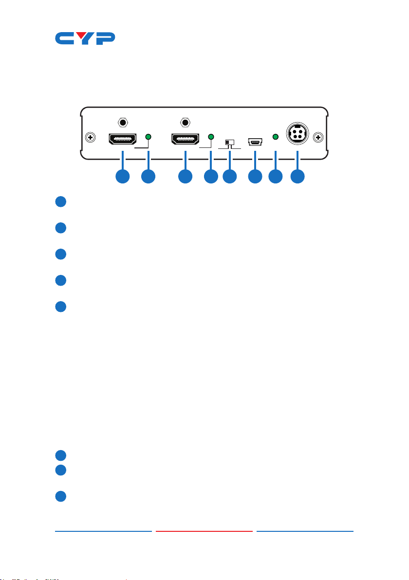
6.1 Front Panel
SYNC LINK EDID SERVICE
HDMI IN POWER
HDMI OUT
DC 24V
STDTV
1 2 3 4 5 6 7 8
1HDMI IN: Connect to HDMI equipped source equipment such as a
DVD/Blu-ray player or games console.
2SYNC LED: This LED will illuminate when the HDMI input is connected
to a HDMI source and receiving a signal.
3HDMI OUT: Connect to a HDMI display for local monitoring of the
HDMI signal or cascade to another Splitter.
4HDMI LINK LED: This LED will illuminate when HDMI output is
connected to TV or display monitor and receiving a signal.
5EDID STD/TV: The default setting is TV, when in this mode, the unit
will detect the EDID settings of the display device connected to
the CAT 5e/6/7 Output 1. If it detects a 4K×2K capable EDID setting
it will transmit the signal in that format to the output port. If no 4K×2K
capable EDID is detected then the unit will detect the EDID settings
and send out the signal that all outputs can accept.
This device has a last memory function and will retain the EDID
settings of the last device connected via the CAT5e/6/7 output
port when it is not connected to a display after power cycling.
Switch to the STD setting to use the unit's built-in EDID if there are
display problems. In this mode, the video output will be set to
1080p@60Hz and the audio at LPCM 2CH Stereo.
6SERVICE: Reserved for manufacture use only.
7POWER LED: The LED will illuminate when connected to an active
power supply.
8DC 24V: Connect the 24V DC power supply to the unit and plug
the adaptor into an AC outlet.

4
6.2 Rear Panel
MODE
LINK
MODE
LINK
MODE
LINK
IR IN IR OUT
23
1
CAT5e/6/7 OUT
1 2 3
1IR IN: Connect the supplied IR Receiver cable for IR signal
reception. Ensure that remote being used is within the direct line-
of-sight of the IR Extender.
2IR OUT: Connect the supplied IR Blaster cable for IR signal
transmission. Place the IR Blaster in direct line-of-sight of the
equipment to be controlled.
3CAT5e/6/7 OUT 1~3: Connect to CAT5e/6/7 to HDMI Receivers with
a single CAT5e/6/7 cable each to extend the HDMI signal up to
100 m.
MODE LED: This LED will illuminate when the power is connected.
LINK LED: This LED will illuminate when connected to a Receiver unit
that is connected with a TV/monitor that is displaying the signal.

5
6.3 IR Cable Pin Assignment
3
1
3
1
2
2
Power 3.3 V
IR Blaster Signal
NC
IR Signal
Power 3.3 V
Grounding
IR Extender
IR Blaster

6
7. CONNECTION DIAGRAM
MODE
LINK
MODE
LINK
MODE
LINK
IR IN IR OUT 231
CAT5e/6/7OUT
SYNC LINK EDID SERVICE
HDMI IN POWER
HDMI OUT
DC 24V
STDTV
RX
IR BLASTER
1.5m
60°
IR RECEIVER
7m
3m 3m
60°
m
Blu-ray Player or
Games Console
Local HDMI Display
HDMI
Input
Power
Supply
CAT 5e/6/7
Outputs
HDMI Output
IR In/Out
HDMI Output
IR In/Out
HDMI Output
IR In/Out
HDTV HDTVHDTV
IR
Extender
IR
Blaster
HDMI
Output

7
8. SPECIFICATIONS
8.1 Technical Specications
Video Bandwidth 340 Mbps/10.2 Gbps
Input Ports 1×HDMI, 1×IR IN, 1×USB (Service only)
Output Ports 1×HDMI, 3×CAT5e/6/7, 1×IR OUT
HDMI Supported
Resolutions
480i~1080p@50/60 Hz, 1080p@24 Hz, 4K×2K
(3840×2160@30 Hz/4096×2160@24/25Hz)
&VGA~WUXGA (RB)
HDMI Input
Cable Distance
10m (1080p@8/12-bit), 5m (4K×2K)
HDMI Output
Cable Distance
15m (1080P@8-bit), 10m (1080p@12-bit),
10m (4K×2K)
IR Frequency 30~50 kHz
Power Supply 24 V/2.7 A DC (US/EU standards, CE/FCC/
UL certied)
Dimensions 145 mm(W)×199 mm(D)×30 mm(H)
Weight 584 g
Chassis Material Metal
Color Black
ESD Protection Human body model:
±8 kV (air-gap discharge)
±4 kV (contact discharge)
Operating Temperature 0 °C ~ 40 °C
Storage Temperature −20 °C ~ 60 °C /−4 °F ~ 140 °F
Relative Humidity 20 ~ 90 % RH (non-condensing)
Power Consumption 33 W

8
8.2 CAT5e/6/7 Cable Specication
CABLE
TYPE
RANGE PIXEL
CLOCK
RATE
VIDEO
DATA
RATE
SUPPORTED
VIDEO
CAT5e/6/7 60 m ≤225 MHz ≤5.3 Gbps
(HD Video)
Up to 1080p, 60 Hz, 36
bits, 3D (data rates
lower than 5.3 Gbps
or below 225MHz
TMDS clock)
40 m >225 MHz > 5.3 Gbps
(Ultra HD
Video)
4Kx2K, 30Hz video
formats
9. ACRONYMS
ACRONYM COMPLETE TERM
4Kx2K Ultra High Denition (3840×2160/4096×2160)
DTS Digital Theater System
EDID Extended Display Identication Data
HDCP High-bandwidth Digital Content Protection
HDMI High-Denition Multimedia Interface
HDTV High-Denition Television


Home page: http://www.cypress.com.tw
CYPRESS TECHNOLOGY CO., LTD
20130531MPM-CHDBT-1H3CL
Table of contents
Other CYP Cables And Connectors manuals