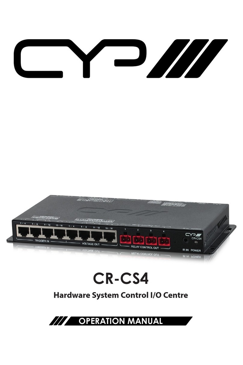
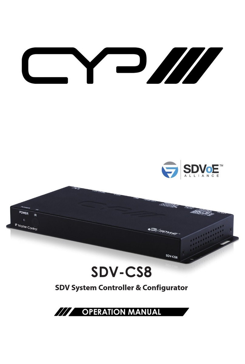
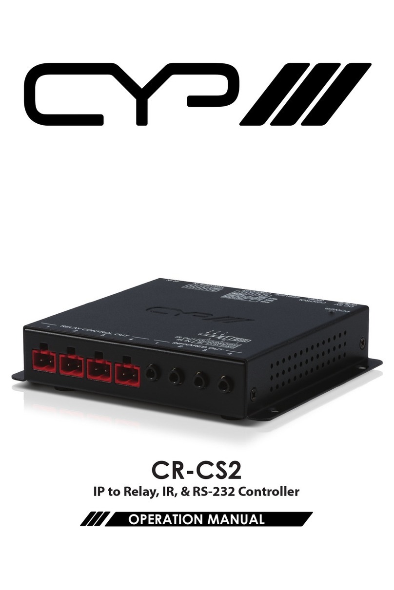
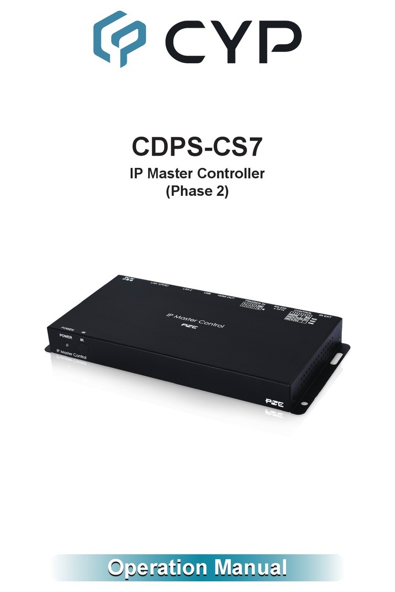
CYP CDPS-CS7-S User manual

CDPS-CS7-S
IP Master Controller (SDVoE)
(Phase 1)
Operation Manual
Operation Manual


DISCLAIMERS
The information in this manual has been carefully checked and
is believed to be accurate. Cypress Technology assumes no
responsibility for any infringements of patents or other rights of third
parties which may result from its use.
Cypress Technology assumes no responsibility for any inaccuracies
that may be contained in this document. Cypress also makes no
commitment to update or to keep current the information contained
in this document.
Cypress Technology reserves the right to make improvements to this
document and/or product at any time and without notice.
COPYRIGHT NOTICE
No part of this document may be reproduced, transmitted,
transcribed, stored in a retrieval system, or any of its part translated
into any language or computer le, in any form or by any means—
electronic, mechanical, magnetic, optical, chemical, manual, or
otherwise—without express written permission and consent from
Cypress Technology.
© Copyright 2018 by Cypress Technology.
All Rights Reserved.
TRADEMARK ACKNOWLEDGMENTS
All products or service names mentioned in this document may be
trademarks of the companies with which they are associated.

SAFETY PRECAUTIONS
Please read all instructions before attempting to unpack, install or
operate this equipment and before connecting the power supply.
Please keep the following in mind as you unpack and install this
equipment:
• Always follow basic safety precautions to reduce the risk of re,
electrical shock and injury to persons.
• To prevent re or shock hazard, do not expose the unit to rain,
moisture or install this product near water.
• Never spill liquid of any kind on or into this product.
• Never push an object of any kind into this product through any
openings or empty slots in the unit, as you may damage parts
inside the unit.
• Do not attach the power supply cabling to building surfaces.
• Use only the supplied power supply unit (PSU). Do not use the PSU
if it is damaged.
• Do not allow anything to rest on the power cabling or allow any
weight to be placed upon it or any person walk on it.
• To protect the unit from overheating, do not block any vents or
openings in the unit housing that provide ventilation and allow for
sufcient space for air to circulate around the unit.
• Please completely disconnect the power when the unit is not in
use to avoid wasting electricity.
REVISION HISTORY
REVISON DATE SUMMARY OF CHANGE
RDV1 2019/05/09 Preliminary release

CONTENTS
1. Introduction......................................................1
2. Applications.....................................................1
3. Package Contents ..........................................2
4. System Requirements......................................2
5. Features............................................................2
6. Operation Controls and Functions.................3
6.1 Front Panel ................................................. 3
6.2 Rear Panel.................................................. 3
6.3 Remote Control......................................... 4
6.4 IR Cable Pinout.......................................... 5
6.5 RS-232 Pinout and Defaults ...................... 5
6.6 WebGUI Control ........................................ 6
6.6.1 Monitor & Control Tab..................... 8
6.6.2 System Tab...................................... 17
6.6.3 Settings Tab .................................... 19
6.6.4 Transmitter Tab ............................... 19
6.6.5 Receiver Tab .................................. 22
6.6.6 Scaling Tab ..................................... 25
6.6.7 Video Wall Tab ............................... 26
6.6.8 MultiView Tab ................................. 28
6.7 Telnet Control .......................................... 30
6.8 RS-232 and Telnet Commands .............. 31
7. Connection Diagram ....................................38
8. Specications ................................................39
8.1 Technical Specications ........................ 39
9. Acronyms .......................................................40

1
1. INTRODUCTION
This IP Master Controller is a powerful and exible solution for
controlling multiple SDVoE (Software Dened Video over Ethernet)
based extenders within same network. The user only needs to install
this unit into the same local network as the extenders (Transmitter and
Receiver) to easily dene and congure channel routing selections
(including video, audio, and a variety of control interface types) using
the WebGUI. Without the use of this centralized control unit, each
Transmitter and Receiver pair would only be able to function in a
point-to-point capacity.
Additionally, this unit supports controlling and conguring the matrix,
video wall, and multiviewer modes of connected SDVoE units. The
settings of all connected Transmitter/Receiver units, including IP
address, netmask and extender status are clearly displayed within
the WebGUI. A trigger input interface is also provided to allow the
easy addition of a remote control keypad, or other trigger-supporting
products, which can be installed within a podium or within a table in
a conference room or classroom. This interface can allow the user to
activate stored presets with the simple press of a button. Standard
control is available via WebGUI (remote or local), RS-232, Telnet and IR
Remote.
2. APPLICATIONS
• Video/TV wall display and control
• Security surveillance and control
• Commercial advertising, display and control
• Home Theaters with Smart Home Controls
• Retail sales and demonstration

2
3. PACKAGE CONTENTS
• 1× IP Master Controller (SDVoE)
• 1× 5V/2.5A DC Power Adapter
• 1× Terminal Block (3-pin)
• 3× Terminal Block (5-pin)
• 1× IR Extender Cable
• 1× Remote Control (CR-183)
• 1× Shockproof Feet (Set of 4)
• 1× Operation Manual
4. SYSTEM REQUIREMENTS
• An active network connection from a switch or router for control of
compatible Video over IP devices.
5. FEATURES
• Enables the management and conguration of multiple compatible
SDVoE (Software Dened Video over Ethernet) extenders through a
single WebGUI
• Provides control over the independent routing of video, audio
and control signals between all local compatible transmitters and
receivers
• Control over matrix, video wall, and multiviewer modes using
WebGUI presets
• WebGUI clearly displays the status of all connected Transmitters and
Receivers, including IP address, channel selection, etc.
• Can generate serial commands to directly control an external serial-
controllable device
• Can be powered by Ethernet switches supporting the IEEE 802.3af
2003 PoE standard (Optional)
• Trigger Control Keypad support for easy, single-button, preset
activation (Optional, coming in the “Phase 2” update)
• Standard control is available via WebGUI (remote or local), RS-232,
Telnet, and IR Remote

3
6. OPERATION CONTROLS AND FUNCTIONS
6.1 Front Panel
POWER IR
IP Master Control
1 2
1POWER LED: This LED will illuminate to indicate the unit is on and
receiving power.
2IR Window: Accepts IR signals from the included IR remote for
control of this unit only.
6.2 Rear Panel
LAN 1(POE)LAN 2USBHDMI OUTRS-232CONTROLIR EXT DC 5V
TRIGGER IN
TX RX
1 2 3 4 5 6 7 8 109
1IR EXT Port: Connect to the provided IR Extender to extend the
IR control range of the unit. Ensure that the remote being used is
within direct line-of-sight of the IR Extender.
2CONTROL Terminal Block: Connect to a serial controllable device
for the transmission of RS-232 signals.
3RS-232 Terminal Block: Connect to a PC, laptop or other serial
control device with a 3-pin adapter cable to control the unit via
RS-232.
4TRIGGER IN Terminal Block: This functionality is not currently
available and will be added in the “Phase 2” update.
5HDMI OUT Port: This functionality is not currently available and will
be added in the “Phase 2” update.
6USB Port: This functionality is not currently available and will be
added in the “Phase 2” update.

4
7LAN 2 Port: Connect directly, or through a network switch, to your
PC/ laptop to control the unit via WebGUI/Telnet.
8LAN 1(POE) Port: This port is used to connect to the SDVoE devices
to be controlled. Connect to the SDVoE units’ private network
through their dedicated network switch, to enable detection and
control over those units.
Note: If the connected network switch supports the IEEE 802.3af
2003 PoE (Power over Ethernet) standard, this unit can optionally
be powered directly via this Ethernet port.
9FACTORY RESET Pinhole: Press and hold for 3 seconds to reset the
unit to its factory defaults, including Ethernet settings.
Note: While the reset is in process, the LEDs on the front of the unit
will ash. Once the reset is complete, the unit will return to normal
operation.
10 DC 5V Port: Plug the 5V DC power adapter into the unit and
connect it to an AC wall outlet for power. (Optional, not required if
the unit is powered via PoE).
6.3 Remote Control
1PRESET 1~8 Buttons: This functionality is not currently
available and will be added in the “Phase 2”
update. 1

5
6.4 IR Cable Pinout
IR Extender
Cabl
e
1
2
3
Infr
ared
Power
Ground
6.5 RS-232 Pinout and Defaults
Serial Port Default Settings
Baud Rate 19200
Data Bits 8
Parity Bits None
Stop Bits 1
Flow Control None
1
2
3
RxD
GND
TxD
3-pin
Terminal Block
1
2
3
4
5RxD
TxD
GN
D
CTS
RTS
5-pin
Terminal Block
Unit Control Serial Output

6
6.6 WebGUI Control
• Device Discovery
Please obtain the “Device Discovery” software from your authorized
dealer and save it in a directory where you can easily nd it.
Connect the unit and your PC/Laptop to the same active network
and execute the “Device Discovery” software. Click on “Find Devices
on Network” and a list of devices connected to the local network will
show up indicating their current IP address.
Note: This unit defaults to DHCP mode. The current IP address can be
veried using the HDMI output (to be added in "Phase 2") or RS-232 if
the Device Discovery software is not available.
By clicking on one of the listed devices you will be presented with the
network details of that particular device.
1) IP Mode: If you choose, you can alter the static IP network settings
for the device, or switch the unit into DHCP mode to automatically
obtain proper network settings from a local DHCP server. To switch
to DHCP mode, please select DHCP from the IP mode drop-down,
then click “Save” followed by “Reboot”.
2) WebGUI Hotkey: Once you are satised with the network settings,
you may use them to connect via Telnet or WebGUI. The network
information window provides a convenient link to launch the
WebGUI directly.

7
• WebGUI Overview
After connecting to the WebGUI’s address in a web browser, the
WebGUI will load and display the System tab. Click “Login" to open
the authentication window. Please enter the appropriate user name
and password then click “Enter” to log in.
Note: The default user name and password is “admin”.
After logging in, on the left side of the browser you will see the
following menu tabs where all primary functions of the unit are
controllable via the built in WebGUI. The individual functions will be
introduced in the following sections.

8
Clicking the “Logout” button within the “System” tab will automatically
log the currently connected user out of the WebGUI and return to
login page.
Note: When not logged in, only the “Monitor & Control” and “System”
tabs are available.
6.6.1 Monitor & Control Tab
This tab provides easy to use drag-and-drop control over all basic
routing functionality of the transmitters and receivers that have been
detected within the local network. Transmitters are represented by
the source icon ( ) and receivers are represented by the display
icon ( ). Each of this tab’s sections control the routing of a different
type of interface that can be found on most compatible transmitters,
receivers or transceivers. These interfaces are: Video routing, HDMI
Audio routing, Analog Audio routing, USB routing, IR routing, and
RS-232 routing. This tab’s controls are available even when a user is
not logged in, providing basic control over routing without exposing
system critical conguration areas.
Note: Units that were previously a part of the system, but are not
currently detected will still be displayed, however they will have a
disconnected icon ( ) and cannot be used for routing.
1) Video Routing: Provides drag-and-drop control over the video
routing between all detected transmitters and receivers.
■ Video Transmitter: This section provides drag-and-drop buttons
for all transmitters detected by the system as well as a button
target to stop one or all video streams from being transmitted.

9
Note: If a transmitter’s streams require more bandwidth than is
available, a warning icon ( ) will be displayed instead of the
normal source icon. Video output from a source displaying
this icon may become visually unstable. It is recommended to
either lower the resolution or framerate of the stream.
Source to Single Receiver Routing: To route a source to a
receiver, click and drag the source’s button on the left to the
preferred display on the right side, then release the mouse
button. If the routing was completed successfully, the newly
routed source’s name will appear below the display’s name
within the button. Clicking on any source button will change
the color of itself, and all currently routed displays.
Note: Receivers may also be drag and dropped onto sources
to activate a new route.
Source to Multiple Receiver Routing: To route a source to
multiple receivers at the same time, click and drag the
source’s button on the left to the “All” button on the right
side, then release the mouse button. If the routing was
completed successfully, the source’s name will appear within
all appropriate buttons.
Stop Stream: To stop the video streams from a single source,
drag the source down to the “Stop” button at the bottom of
the window, then release the mouse button. To stop ALL video
streams, drag the “All” button down to the “Stop” button.
■ Video Receiver: This section provides drag-and-drop buttons for
all receivers detected by the system as well as a button target
to stop one or all output streams from being displayed.
Stop Stream: To stop the video stream on a single display, drag
the display down to the “Stop” button at the bottom of the
window, then release the mouse button. To stop ALL video
outputs, drag the “All” button down to the “Stop” button.

10
2) HDMI Audio Routing: Provides drag-and-drop control over the
independent HDMI audio routing of all detected transmitters and
receivers.
Note: Bitstream audio is only supported when the receiver’s
HDMI audio device setting is set to “HDMI Audio (Follow Video in
Genlock Mode)”.
■ HDMI Audio Transmitter: This section provides drag-and-drop
buttons for all transmitters detected by the system as well as
a button target to stop one or all independent HDMI audio
streams from being transmitted.
Source to Single Receiver Routing: To route an HDMI audio
source to a receiver, click and drag the source’s button on the
left to the preferred display on the right side, then release the
mouse button. If the routing was completed successfully, the
newly routed source’s name will appear below the display’s
name within the button. Clicking on any source button will
change the color of itself, and all currently routed displays.
Note: Receivers may also be drag and dropped onto sources
to activate a new route.
Source to Multiple Receiver Routing: To route an HDMI audio
source to multiple receivers at the same time, click and drag
the source’s button on the left to the “All” button on the
right side, then release the mouse button. If the routing was
completed successfully, the source’s name will appear within
all appropriate buttons.

11
Stop Stream: To stop the independent HDMI audio stream from
a single source, drag the source down to the “Stop” button
at the bottom of the window, then release the mouse button.
To stop ALL independent HDMI audio streams, drag the “All”
button down to the “Stop” button.
Note: When a receiver’s HDMI Audio is set to “Follow Video in
Genlock Mode”, and scaling on that output has been disabled,
the audio output on that receiver will not be stopped.
■ HDMI Audio Receiver: This section provides drag-and-drop
buttons for all receivers detected by the system as well as
a button target to stop one or all independent HDMI audio
streams.
Note: When a receiver’s HDMI Audio is set to “Follow Video in
Genlock Mode” and scaling on that output has been disabled,
the HDMI audio setting is ignored and the audio embedded
with the HDMI source will always be output. In these instances a
(!) mark will be displayed.
Stop Stream: To stop the HDMI audio stream on a single display,
drag the display down to the “Stop” button at the bottom of
the window, then release the mouse button. To stop ALL video
outputs, drag the “All” button down to the “Stop” button.
Note: When a receiver’s HDMI Audio is set to “Follow Video in
Genlock Mode”, and scaling on that output has been disabled,
the independent audio route will be stopped, however the
HDMI embedded audio will continue to be output normally.

12
3) Analog Audio Routing: Provides drag-and-drop control over the
routing of analog audio input streams between all detected
transmitters and receivers.
■ Analog Audio Transmitter: This section provides drag-and-drop
buttons for all analog input sources detected by the system as
well as a button target to stop one or all analog audio streams
from being transmitted.
Source to Single Receiver Routing: To route an analog audio
source to a receiver, click and drag the source’s button on the
left to the preferred receiver on the right side, then release the
mouse button. If the routing was completed successfully, the
newly routed source’s name will appear below the receiver’s
name within the button. Clicking on any source button will
change the color of itself, and all currently routed receivers.
Note: Receivers may also be drag and dropped onto sources
to activate a new route.
Source to Multiple Receiver Routing: To route an analog audio
source to multiple receivers at the same time, click and drag
the source’s button on the left to the “All” button on the
right side, then release the mouse button. If the routing was
completed successfully, the source’s name will appear within
all appropriate buttons.
Stop Stream: To stop the analog audio stream from a single
source, drag the source down to the “Stop” button at the
bottom of the window, then release the mouse button. To stop
ALL analog audio streams, drag the “All” button down to the
“Stop” button.
■ Analog Audio Receiver: This section provides drag-and-drop
buttons for all analog audio outputs detected by the system as
well as a button target to stop the output of one or all analog
audio streams.
Note: If the selected audio source for an analog output has
been set to “HDMI Audio (Stereo Downmix)” that output will be
marked with a (!) and the audio output will mirror the source
set on the HDMI Audio routing page.
Stop Stream: To stop the analog audio output on a single
receiver, drag the receiver down to the “Stop” button at the
bottom of the window, then release the mouse button. To stop

13
ALL video outputs, drag the “All” button down to the “Stop”
button.
Note: If the selected audio source for an analog output has
been set to “HDMI Audio (Stereo Downmix)” the audio output
can only be stopped from the HDMI Audio page.
4) USB Pairing: Provides drag-and-drop control over the pairing of
USB hosts (PC, laptop, etc.) and USB devices (keyboard, mouse,
webcam, etc.) between the ports detected on all transmitters and
receivers.
Note: When a USB host port has enabled “Simultaneous Mode”,
it can be paired with up to 7 device endpoints. If “Simultaneous
Mode” is disabled, a USB host port can only be paired with a single
USB device endpoint.
■ USB Host: This section provides drag-and-drop buttons for
detected USB host ports as well as a button target to stop
communication from a host.
Host to Device Pairing: To pair a USB host with a USB device,
click and drag the USB host’s button on the left to the preferred
USB device on the right side, then release the mouse button. If
the pairing was completed successfully, the active USB host’s
name will appear below the USB device’s name within the
button. Clicking on any USB host button will change the color
of itself, and all currently paired USB device endpoints.
Note: USB devices may also be drag and dropped onto USB
hosts to activate a new pairing.

14
Stop Host: To stop communication from a USB host, drag the
USB host down to the “Stop” button at the bottom of the
window, then release the mouse button.
■ USB Device: This section provides drag-and-drop buttons for all
detected USB device endpoints as well as a button target to
stop communication from a device.
Stop Device: To stop communication from a USB device, drag
the USB device down to the “Stop” button at the bottom of the
window, then release the mouse button.
5) IR Routing: Provides drag-and-drop control over the routing of the
IR inputs and outputs detected on all transmitters and receivers.
Note: An IR output can be routed to by multiple IR inputs, however
each IR input may only be directly routed to a single IR output. If
an IR input needs to be sent to more than one output, the Global
Broadcast option must be used.
■ IR Input: This section provides drag-and-drop buttons for all IR
input ports detected by the system as well as a button target
to stop one or all IR streams from being transmitted.
IR Input Global Broadcast: To broadcast an IR input to all
available IR outputs, click and drag the IR input’s button on
the left to the “All” button on the right side, then release the
mouse button. If the routing was completed successfully, the
IP broadcast address (255.255.255.255) will appear within the
appropriate IR input’s button.
Stop Stream: To stop the broadcast of an IR signal from a single
IR input, drag the IR input down to the “Stop” button at the

15
bottom of the window, then release the mouse button. To stop
the transmission of ALL IR signals, drag the “All” button down to
the “Stop” button.
■ IR Output: This section provides drag-and-drop buttons for all
IR output ports detected by the system. Each IR output has an
automatically assigned IR stream IP address listed below the
output’s name.
IR Output to IR Input Routing: To connect an IR output to an
IR input, click and drag the IR output’s button on the right to
the preferred IR input on the left side, then release the mouse
button. If the routing was completed successfully, the newly
routed IR output’s IR stream IP address will appear below the IR
input’s name within its button. Clicking on any IR output button
will change the color of itself, and all IR inputs currently routed
to it.
Note: IR inputs may also be drag and dropped onto IR outputs
to activate a new route.
6) RS-232 Routing: Provides drag-and-drop control over the routing of
the RS-232 senders and receivers detected on all transmitters and
receivers. The RS-232 port on a standard extension unit contains
one sender (Rx pin) and one receiver (Tx pin).
Note: An RS-232 receiver can be routed to by multiple RS-232
senders, however each RS-232 sender may only be directly routed
to a single RS-232 receiver. If an RS-232 sender needs to be sent
to more than one receiver, the Global Broadcast option must be
used.
Table of contents
Other CYP Controllers manuals
Popular Controllers manuals by other brands

Linear Technology
Linear Technology DC2465A Demo Manual

Maxcess
Maxcess H6630EM user manual

Emerson
Emerson Bettis RGS Q-Series Installation, operation and maintenance manual

3Ware
3Ware 9590SE Series Quick install guide

ETC
ETC ArcSystem Pro D4 Series installation guide

4O3A
4O3A Station Genius v2 user manual

ASE
ASE DS-2C installation manual

Johnson Controls
Johnson Controls Joventa DMS1.1 installation instructions

Sullair
Sullair WSPC user manual

Siemens
Siemens N 523/11 Technical product information

Galcon
Galcon AMC-6DC user guide

Taconova
Taconova FWCK Installation and operating instructions for manual and remote control options