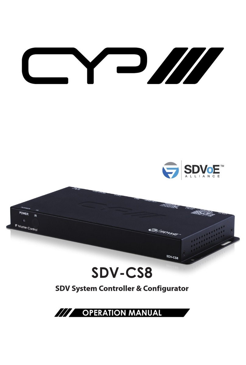
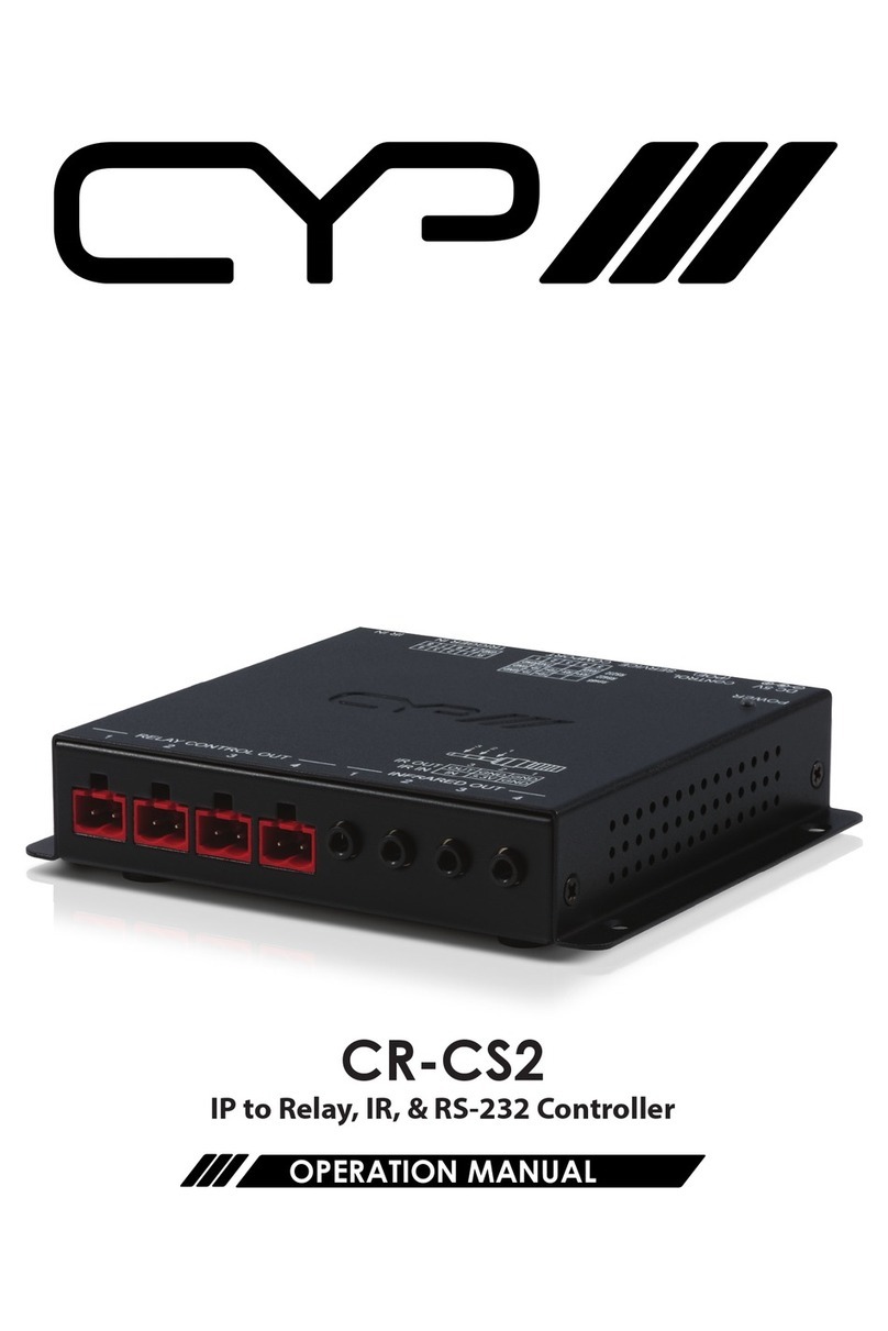
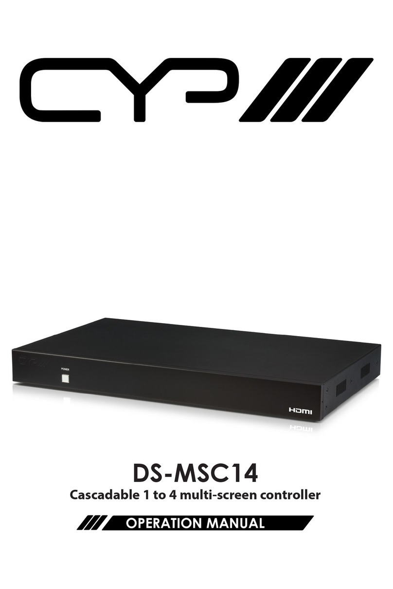
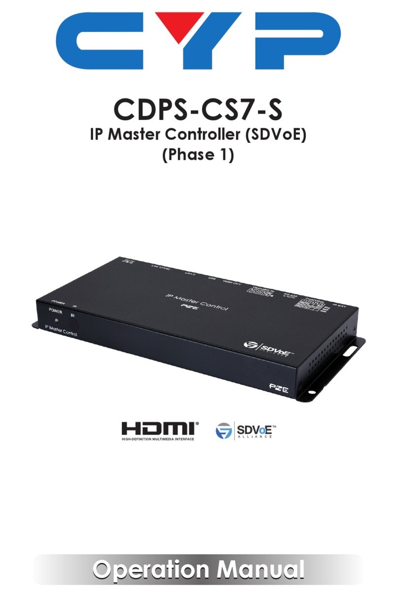
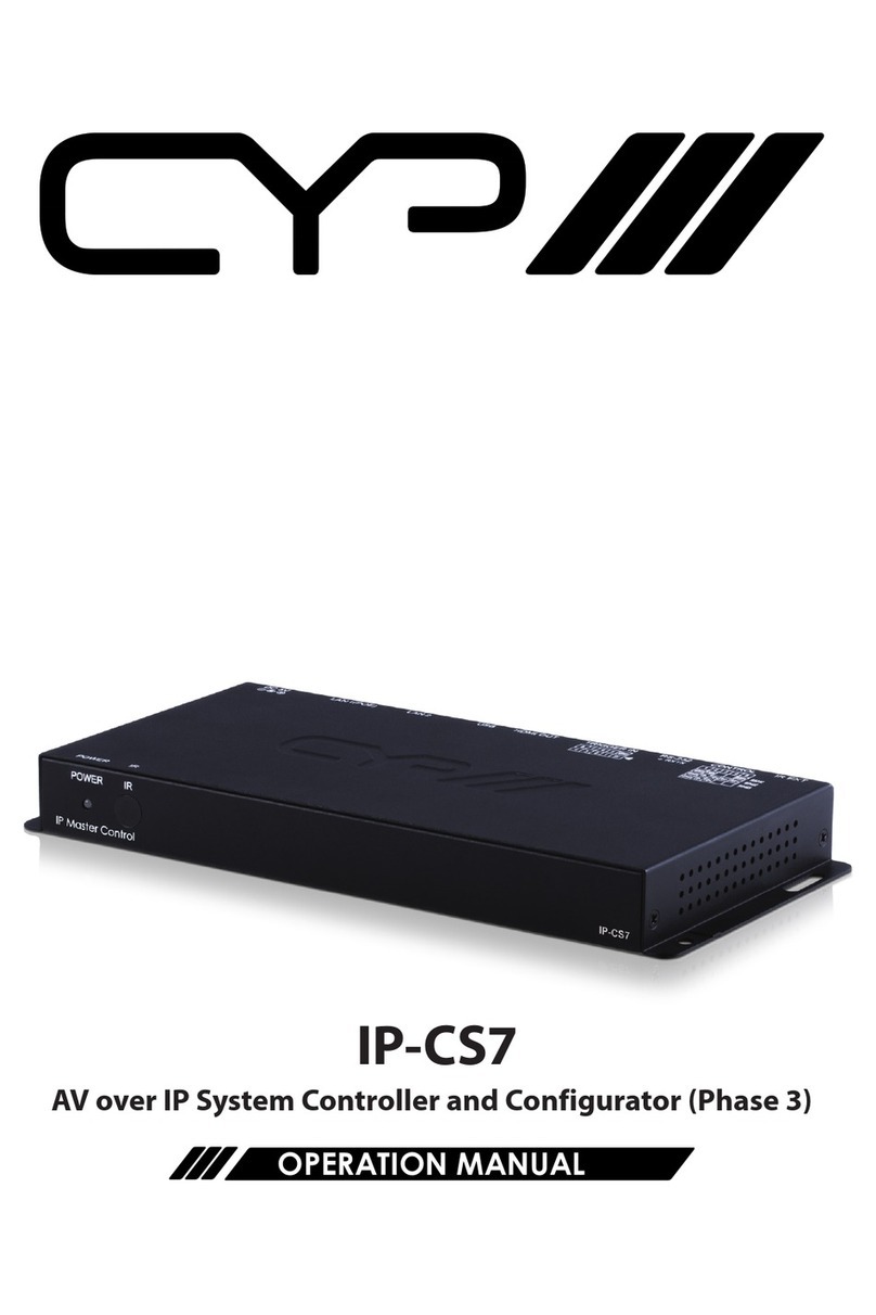
CYP IP-CS7 User manual

IP-CS7
IP System Controller & Configurator
OPERATION MANUAL


3
DISCLAIMERS
The information in this manual has been carefully checked and is
believed to be accurate. CYP (UK) Ltd assumes no responsibility for any
infringements of patents or other rights of third parties which may result
from its use.
CYP (UK) Ltd assumes no responsibility for any inaccuracies that may be
contained in this document. CYP (UK) Ltd also makes no commitment to
update or to keep current the information contained in this document.
CYP (UK) Ltd reserves the right to make improvements to this document
and/or product at any time and without notice.
COPYRIGHT NOTICE
No part of this document may be reproduced, transmitted, transcribed,
stored in a retrieval system, or any of its part translated into any language
or computer file, in any form or by any means—electronic, mechanical,
magnetic, optical, chemical, manual, or otherwise—without express
written permission and consent from CYP (UK) Ltd.
© Copyright 2011 by CYP (UK) Ltd.
All Rights Reserved.
Version 1.1 August 2011
TRADEMARK ACKNOWLEDGMENTS
All products or service names mentioned in this document may be
trademarks of the companies with which they are associated.

4
SAFETY PRECAUTIONS
Please read all instructions before attempting to unpack, install or operate
this equipment and before connecting the power supply.
Please keep the following in mind as you unpack and install this
equipment:
• Always follow basic safety precautions to reduce the risk of fire,
electrical shock and injury to persons.
• To prevent fire or shock hazard, do not expose the unit to rain,
moisture or install this product near water.
• Never spill liquid of any kind on or into this product.
• Never push an object of any kind into this product through any
openings or empty slots in the unit, as you may damage parts inside
the unit.
• Do not attach the power supply cabling to building surfaces.
• Use only the supplied power supply unit (PSU). Do not use the PSU if
it is damaged.
• Do not allow anything to rest on the power cabling or allow any
weight to be placed upon it or any person walk on it.
• To protect the unit from overheating, do not block any vents or
openings in the unit housing that provide ventilation and allow for
sufficient space for air to circulate around the unit.
REVISION HISTORY
VERSION NO. DATE SUMMARY OF CHANGE
v1.00 09/03/2018 First release

5
CONTENTS
1. Introduction...........................................6
2. Applications ...........................................6
3. Package Contents ..................................6
4. System Requirements ...........................7
5. Features..................................................7
6. Operation Controls and Functions .......8
6.1 Front Panel................................................... 8
6.2 Rear Panel..................................................... 8
6.3 Remote Control.......................................... 9
6.4 IR Cable Pinouts .......................................10
6.5 Serial Control.............................................10
6.6 Telnet Control............................................11
6.7 RS-232 and Telnet Commands............12
6.8 WebGUI Control .......................................18
7. Connection Diagram .......................... 31
8. Specifications...................................... 32
9. Acronyms............................................. 33

6
1. INTRODUCTION
This controller is a powerful and exible solution for controlling multiple
Video over IP (VoIP) extenders within same network. The user only needs
to install this unit into the same local network as the extenders (Transmit-
ter and Receiver) to easily dene and congure channel routing selec-
tions, for both unicast and multicast scenarios, using the WebGUI. It is also
possible to dene and switch routes using customised groups or presets
allowing for easy control over multiple video zones. Without the use of
this centralised unit, each individual Transmitter and Receiver in the sys-
tem would need to be controlled and congured directly through their
own WebGUI.
Additionally, this unit supports controlling the matrix and video wall
modes of connected VoIP units. The settings of all connected Transmit-
ter/Receiver units, including IP address, netmask and extender status are
clearly displayed within the WebGUI. The WebGUI is easily accessed via a
web browser over a normal network connection or by directly connecting
an HDMI display and USB keyboard & mouse to the unit. A trigger input
interface is also provided to allow the easy addition of a remote control
keypad, or other trigger-supporting products, which can be installed
within a podium or within a table in a conference room or classroom. This
interface can allow the user to activate pre-dened functions or presets
with the simple press of a button. Standard control is available via Web-
GUI (remote or local), RS-232, Telnet and IR Remote.
2. APPLICATIONS
Video/TV wall display and control
Security surveillance and control
Commercial advertising, display and control
Home Theaters with Smart Home Controls
Retail sales and demonstration
3. PACKAGE CONTENTS
1×IP Master Controller
1×5V/2.6A DC Power Adapter
1×Terminal Block (3-pin)

7
3×Terminal Block (5-pin)
1×3.5mm to IR Extender Cable
1×Remote Control (CR-183)
1×Shockproof Feet (Set of 4)
1×Operation Manual
4. SYSTEM REQUIREMENTS
An active internet connection from a switch or router for control of
Ethernet devices.
5. FEATURES
Enables the management and conguration of multiple Video over IP
(VoIP) extenders through a single WebGUI
Supports point-to-point (unicast) and multi-to-multi (multicast) rout-
ing selections
Control over both matrix and TV wall modes using WebGUI presets
Denable display groups
WebGUI clearly displays the status of all connected Transmitters and
Receivers, including IP address, channel selection, etc.
Able to control an additional connected device via RS-232
HDMI output displays the WebGUI and system status
Supports the use of a USB mouse and keyboard to locally control the
WebGUI (Optional)
Can be powered by Ethernet switches supporting the IEEE 802.3af-
2003 PoE standard (Optional)
Trigger Control Keypad support for easy, single-button, preset activa-
tion (Optional)
Standard control is available via WebGUI (remote or local), RS-232,
Telnet, and IR Remote

8
6. OPERATION CONTROLS AND FUNCTIONS
6.1 Front Panel
POWER IR
IP Master Control
1 2
1POWER LED: This LED will illuminate to indicate the unit is on and
receiving power.
2IR WINDOW: Accepts IR signals from the included IR remote for
control of this unit only.
6.2 Rear Panel
LAN 1(POE)LAN 2USBHDMI OUTRS-232CONTROLIR EXT DC 5V
TRIGGER IN
TX RX
1 2 3 4 5 6 7 8 9
1IR EXT: Connect to the provided IR Extender to extend the IR control
range of the unit. Ensure that the remote being used is within direct
line-of-sight of the IR Extender.
2CONTROL: Connect to the device you wish to control via a 3 (or 5)-pin
adapter cable to send RS-232 commands from the unit.
3RS-232: Connect to a PC, laptop or other serial control device with a
3-pin adapter cable to control the unit via RS-232.
4TRIGGER IN: Connect to the Trigger Control Keypad (OPTIONAL) or
any device with trigger switch functionality such as window security
alarms, motion detectors, door switches, etc. Each of the 8 trigger
inputs will activate the associated preset when triggered. A minimum
of 5V DC is required to activate the trigger.
5HDMI OUT: Connect to a standard HDMI display to view the unit’s
current status information and access the WebGUI directly without
a PC.

9
6USB: Connect a USB mouse and keyboard to control the unit’s
WebGUI as seen via the HDMI output port. Firmware update via USB is
also supported.
7LAN 2: Connect directly, or through a network switch, to your PC/
laptop to control the unit via WebGUI/Telnet.
8LAN 1 (PoE): This port is used to connect to the Video over IP (VoIP)
devices to be controlled. Connect to the VoIP units’ private network,
either directly or through their dedicated network switch, to enable
detection and control over those units.
Note 1: Typically the VoIP device network is contained within in a separate
subnet or, more frequently, in a physically separate network.
Note 2: If the connected network switch supports the IEEE 802.3af-2003
PoE (Power over Ethernet) standard, this unit can optionally be powered
directly via this Ethernet port.
9DC 5V: Plug the 5V DC power adapter into the unit and connect it to
an AC wall outlet for power. (Optional, not required if the unit is pow-
ered via PoE).
6.3 Remote Control
1MACRO 1~12: Press any of the 12 buttons to activate
the saved preset assigned to that number. 2
1
3
4
5
6
8
7
9
10
11
12
CR-183
MACRO
1

10
6.4 IR Cable Pinouts
3
1
2
Infrared
Power
Ground
IR Extender
6.5 Serial Control
UNIT PC SERIAL PORT SETTINGS
Pin Pinout Pin Pinout Baud Rate 115200
1Data Bits 8
1TxD 2 RxD Parity Bit None
2 RxD 3 TxD Stop Bits 1
4Flow Control None
3 GND 5 GND
6
7
8
9

11
6.6 Telnet Control
Before attempting to use Telnet control, please ensure that both the unit’s
LAN 2 port and the PC/laptop are connected to the same active networks.
To Access the Command Line Interface (CLI)
Windows 7 Click Start, type “cmd” in the search eld, and press
Enter.
Windows XP Click Start > Run, type “cmd”, and press Enter.
Mac OS X Click Go > Applications > Utilities > Terminal.
Once in the CLI (Command Line Interface) type “telnet” followed by the
IP address of the unit and “23”, then hit “Enter”. This will connect us to the
unit we wish to control. Type “help”to list the available commands.
Note 1: By default the unit will obtain the LAN 2 IP address via DHCP. If you
are unsure of the unit’s current LAN 2 IP address, please check the unit’s HDMI
status display.
Note 2: Commands will not be executed unless followed by a carriage return.
Commands are not case-sensitive.
Note 3: If the unit's IP address is changed then the IP address required for
Telnet access will also change accordingly.

12
6.7 RS-232 and Telnet Commands
SYSTEM COMMANDS
DESCRIPTION PARAMETERS
HELP
Show the full command list.
GET_HARDWARE_VERSION
Show the unit’s hardware version.
GET_FIRMWARE_VERSION
Show the unit’s current rmware
version.
SET_FACTORY_RESET
Reset the unit to the factory de-
faults.
SET_HISTORY_RESET
Clear the unit’s stored transmitter
and receiver history list.
REBOOT
Reboot the unit.

13
NETWORK COMMANDS
DESCRIPTION PARAMETERS
GET_IPCONFIG N1
Show the current Ethernet con-
guration of the selected port.
Available values for N1:
1 [LAN Port 1]
2 [LAN Port 2]
SET_IP_MODE N1 N2
Set the IP assignment mode for the
selected LAN port.
Available values for N1:
1 [LAN Port 1]
2 [LAN Port 2]
Available values for N2:
0 [Static IP]
1 [DHCP]
2 [Auto IP]
GET_IP_MODE N1
Show the IP assignment mode for
the selected LAN port.
Available values for N1:
1 [LAN Port 1]
2 [LAN Port 2]
SET_IP_ADDRESS N1 N2
Set the IP address for the selected
LAN port.
Available values for N1:
1 [LAN Port 1]
2 [LAN Port 2]
N2 = X.X.X.X [X = 0 ~ 255]
GET_IP_ADDRESS N1
Show the current IP address of the
selected LAN port.
Available values for N1:
1 [LAN Port 1]
2 [LAN Port 2]

14
NETWORK COMMANDS
DESCRIPTION PARAMETERS
SET_NETMASK N1 N2
Set the netmask for the selected
LAN port.
Available values for N1:
1 [LAN Port 1]
2 [LAN Port 2]
N2 = X.X.X.X [X = 0 ~ 255]
GET_NETMASK N1
Show the current netmask of the
selected LAN port.
Available values for N1:
1 [LAN Port 1]
2 [LAN Port 2]
SET_GATEWAY N1 N2
Set the gateway address for the
selected LAN port.
Available values for N1:
1 [LAN Port 1]
2 [LAN Port 2]
N2 = X.X.X.X [X = 0 ~ 255]
GET_GATEWAY N1
Show the current gateway address
of the selected LAN port.
Available values for N1:
1 [LAN Port 1]
2 [LAN Port 2]
DISCOVERY SERVICE COMMANDS
DESCRIPTION PARAMETERS
GET_TX_DEVICE
List all supported VoIP Transmitter
devices detected on LAN port 1’s
local network.

15
DISCOVERY SERVICE COMMANDS
DESCRIPTION PARAMETERS
GET_RX_DEVICE
List all supported VoIP Receiver
devices detected on LAN port 1’s
local network.
MACRO/GROUP COMMANDS
DESCRIPTION PARAMETERS
MACRO_RUN N1
Run preset (macro) N1. N1 = 1 ~ 255 [Preset Number]
GET_MACRO_RUN N1
List the contents of preset (macro)
N1.
N1 = 1 ~ 255 [Preset Number]
SET_GROUP_ROUTE N1 N2
Set all members of Group N1 to
display Channel N2.
N1 = 1 ~ 255 [Group Number]
N2 = 0 ~ 255 [Channel Number]
GET_GROUP_MEMBER N1
List all Receivers in group N1. N1 = 1 ~ 255 [Group Number]
INDIVIDUAL VOIP UNIT COMMANDS
DESCRIPTION PARAMETERS
SET_CHANNEL N1 N2
Set the channel for the Tx or Rx at
IP address N1.
N1 = X.X.X.X [X = 0 ~ 255,
IP of Target Unit]
N2 = 0~255 [Channel Number]
GET_CHANNEL N1
Show the current channel used by
the Tx or Rx at IP address N1.
N1 = X.X.X.X [X = 0 ~ 255,
IP of Target Unit]

16
INDIVIDUAL VOIP UNIT COMMANDS
DESCRIPTION PARAMETERS
SET_DEVICE_NAME N1 N2
Set the name of the Tx or Rx at IP
address N1.
N1 = X.X.X.X [X = 0 ~ 255,
IP of Target Unit]
N2 = {Name} [Alpha-numeric,
12 Chars Max]
GET_DEVICE_NAME N1
Show the current name of the Tx or
Rx at IP address N1.
N1 = X.X.X.X [X = 0 ~ 255,
IP of Target Unit]
SET_NET_MODE N1 N2
Set the network broadcast mode
of the Tx or Rx at IP address N1.
N1 = X.X.X.X [X = 0 ~ 255,
IP of Target Unit]
Available values for N2:
0 [Unicast Mode]
1 [Multicast Mode]
GET_NET_MODE N1
Show the current network
broadcast mode of the Tx or Rx at
IP address N1.
N1 = X.X.X.X [X = 0 ~ 255,
IP of Target Unit]
SET_VW_LAYOUT N1 N2 N3
Set the horizontal and vertical
display count of the video wall that
the Rx at IP address N1 is a part of.
N1 = X.X.X.X [X = 0 ~ 255,
IP of Target Unit]
N2 = 1 ~ 16 [Horizontal Display
Count]
N3 = 1 ~ 16 [Vertical Display
Count]

17
INDIVIDUAL VOIP UNIT COMMANDS
DESCRIPTION PARAMETERS
GET_VW_LAYOUT N1
Show the horizontal and vertical
display count of the video wall that
the Rx at IP address N1 is a part of.
N1 = X.X.X.X [X = 0 ~ 255,
IP of Target Unit]
SET_VW_POS N1 N2 N3
Set the horizontal and vertical
position of the Rx at IP address N1
within the defined video wall.
N1 = X.X.X.X [X = 0 ~ 255,
IP of Target Unit]
N2 = 0 ~ 15 [Horizontal Position]
N3 = 0 ~ 15 [Vertical Position]
Note: Cannot exceed the dimensions defined by VW_LAYOUT.
GET_VW_POS N1
Show the horizontal and vertical
position of the Rx at IP address N1
within the defined video wall.
N1 = X.X.X.X [X = 0 ~ 255,
IP of Target Unit]

18
6.8 WebGUI Control
Device Discovery Tool
Please obtain the “Device Discovery” software from your authorised dealer
and save it in a directory where you can easily find it.
Connect the unit and your PC/laptop to the same active network and
execute the “Device Discovery” software. Click on “Find Devices on
Network” and a list of devices connected to the local network will show
up indicating their current IP address.
By clicking on one of the listed devices you will be presented with the
network details of that particular device.
-IP Mode: If you choose, you can alter the static IP network settings
for the device, or switch the unit into DHCP mode to automatically
obtain proper network settings from a local DHCP server. To switch to
DHCP mode, please select DHCP from the IP mode drop-down, then
click “Save” followed by “Reboot”.
-WebGUI Hotkey: Once you are satisfied with the network settings,
you may use them to connect via Telnet or WebGUI. The network
information window provides a convenient link to launch the
“WebGUI” directly.

19
WebGUI Control Page
All functions of this unit are controllable via the built in WebGUI which
is accessed by connecting your web browser to LAN 2’s IP address or by
connecting an HDMI display to the unit’s HDMI output and attaching a
USB mouse and keyboard to the unit’s USB port. This control is presented
across a number of separate tabs, including Monitor & Control, Preset
Recall, System, Setting, Transmitter, and Receiver. A setup wizard is also
provided to help simplify first-time setup. The individual functions will be
introduced in the following sections.
When no user is logged in, a limited selection of tabs are available (Monitor
& Control, Preset Recall, and System). This allows for easy user access to
routing selection and presets while still protecting the more sensitive
and critical setup and configuration controls. To log in to the WebGUI,
switch to the System tab and click on the “Login”button. By default,
both the Username and Password are set to “admin” for the WebGUI. The
administrator password can be changed within the System tab of the
WebGUI if desired.
iIf you are unsure of the unit’s current LAN 2 IP address, please check the
unit’s HDMI status display.

20
6.8.1 Monitor & Control Tab
This tab provides a graphical representation of all current Transmitters,
Receivers and video groups. It also provides a simple way to change video
routing by using drag and drop. Using the slider switch at the top of the
tab, video thumbnails may be set to automatically update (Auto Refresh),
or to only update when the“Refresh” button is clicked (Manual Refresh).
iThis tab is fully functional even when the user is logged out.
Source Preview
This window displays preview thumbnails from all detected Transmitters
along with their assigned names. If Auto Refresh is enabled, the
thumbnails will update aproximately once every second. To route a
Transmitter’s source to a different Receiver, or to a video group, drag-and-
drop can be used. Click and drag the thumbnail from the Preview side to
drop it onto the prefered Receiver or Display Group on the Zone side.
Zone Preview
This window displays preview thumbnails from all detected Receivers
along with their assigned names. If Auto Refresh is enabled, the
thumbnails will update aproximately once every second. All available
Display Groups are also displayed here, however no preview thumbnail
will be displayed for them. Display Groups are defined within the Setting
tab.
iDue to the potential for the displays within a video group to be showing
different sources, video groups will not show a thumbnail image.
Other manuals for IP-CS7
1
Table of contents
Other CYP Controllers manuals
Popular Controllers manuals by other brands

Johnson Controls
Johnson Controls tyco PowerSeries Neo Reference manual

Siemens
Siemens OpenAir GLB141.1P Technical instructions

Siemens
Siemens FLN installation instructions

Reclaim
Reclaim v1 manual

Ohmeron
Ohmeron LSC12 manual

Morningstar
Morningstar TRISTAR TS-MPPT-60-600V-48-DB Installation, operation and maintenance manual