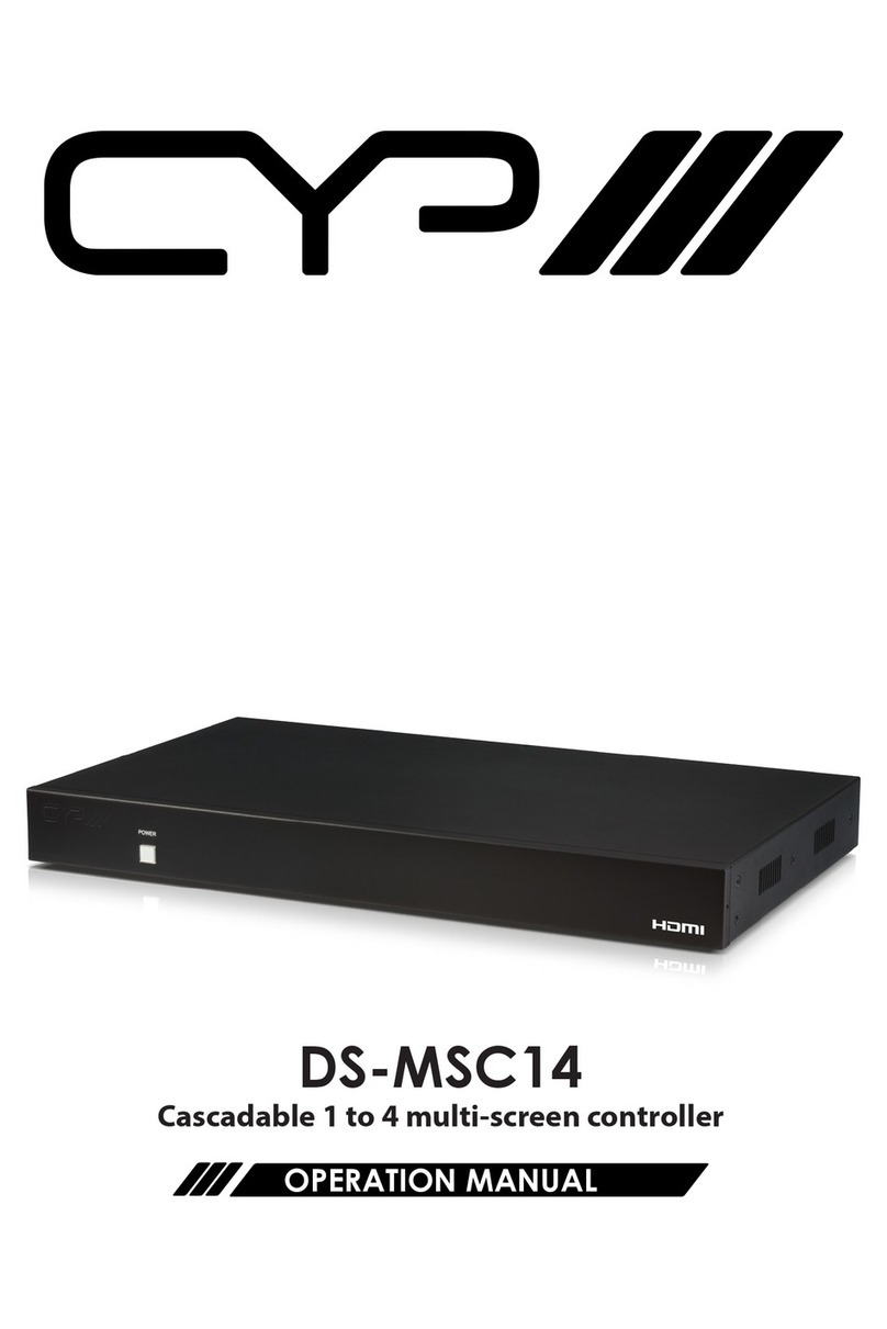
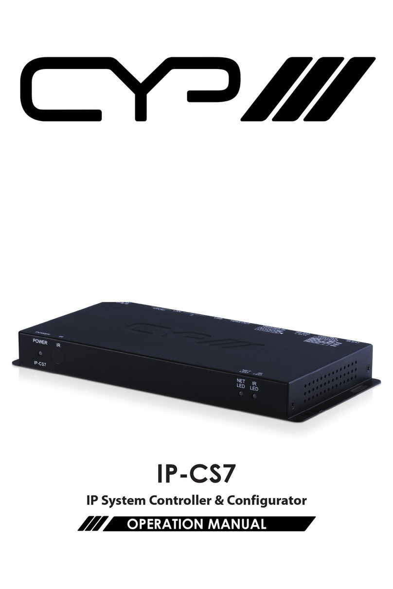
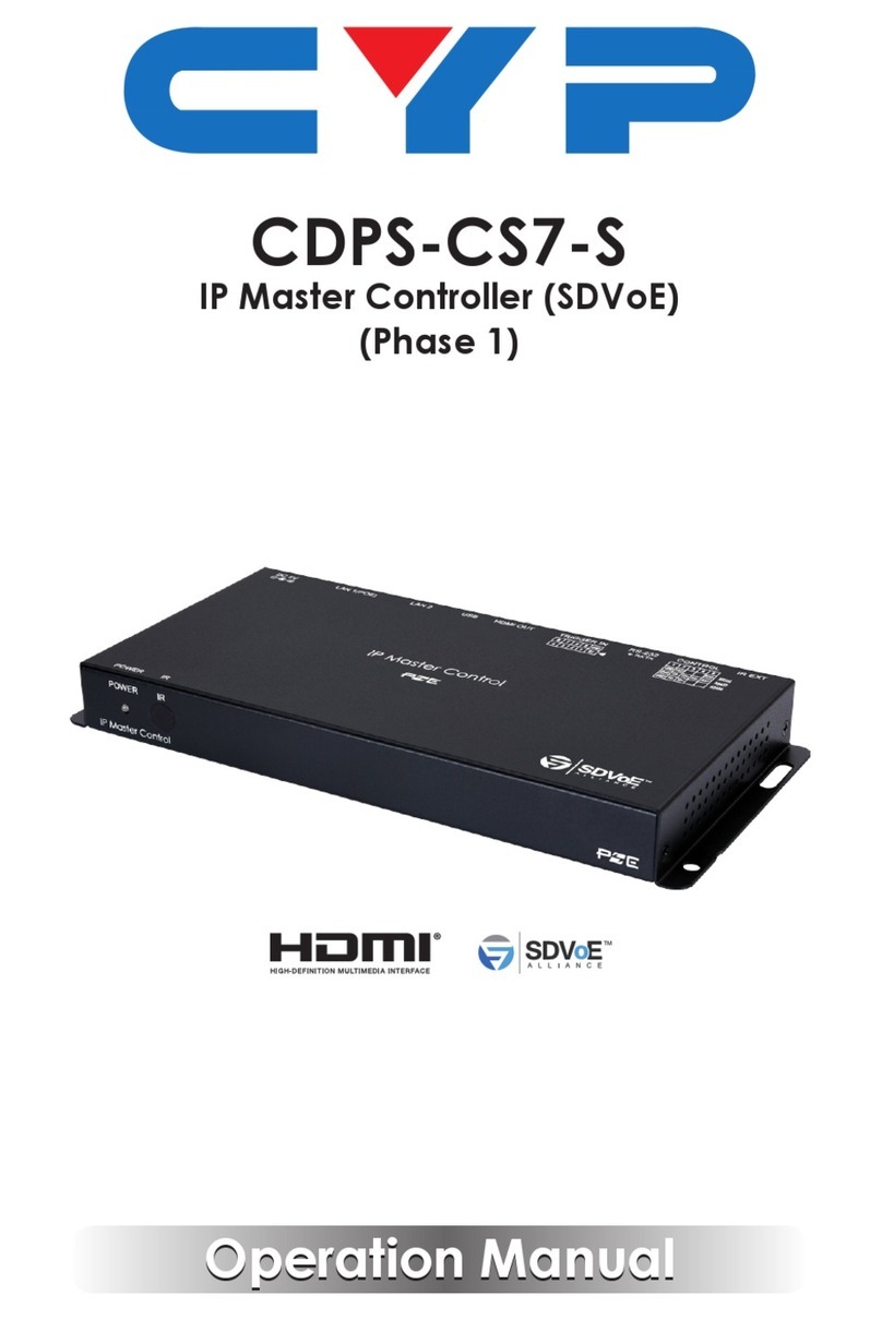
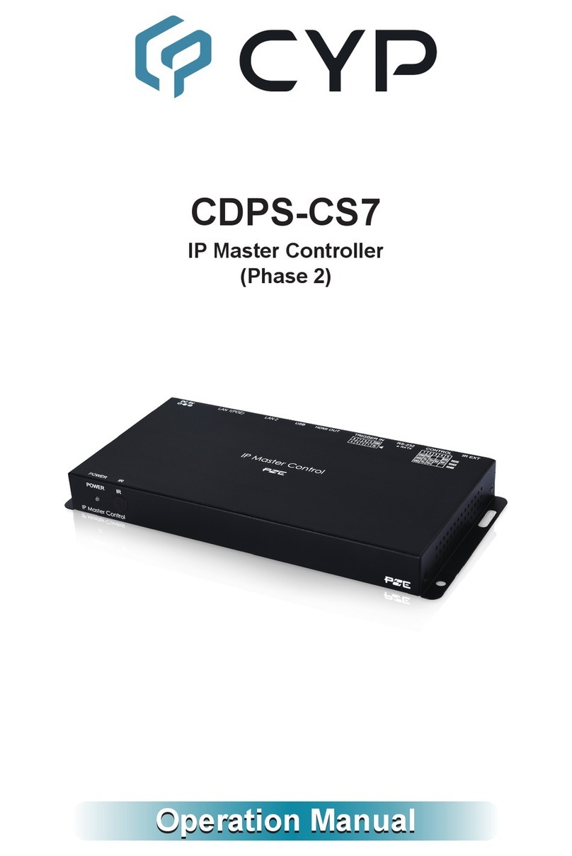
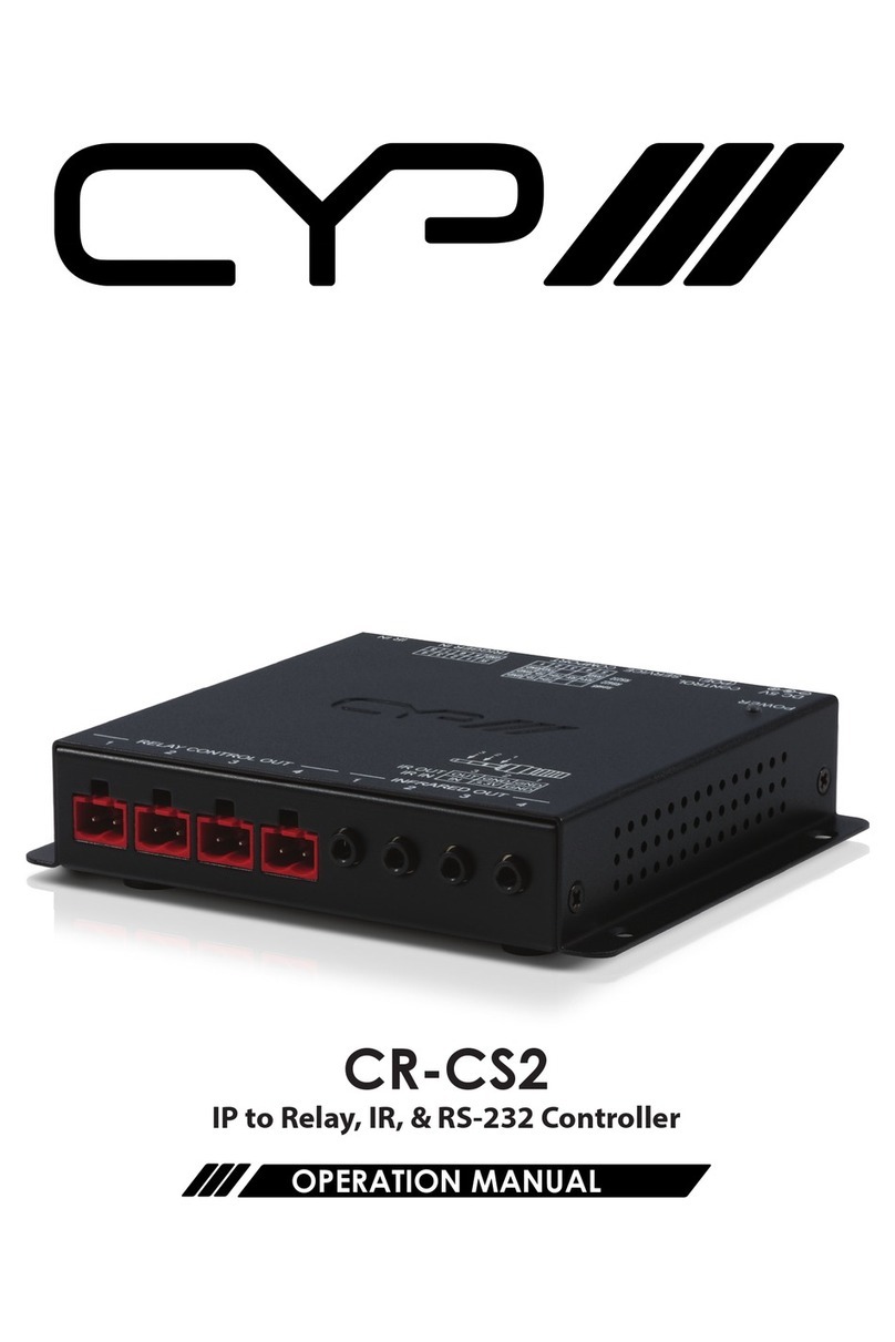
CYP CR-CS4 User manual

CR-CS4
Hardware System Control I/O Centre
OPERATION MANUAL


DISCLAIMERS
The information in this manual has been carefully checked and is
believed to be accurate. CYP (UK) Ltd assumes no responsibility for any
infringements of patents or other rights of third parties which may result
from its use.
CYP (UK) Ltd assumes no responsibility for any inaccuracies that may be
contained in this document. CYP (UK) Ltd also makes no commitment to
update or to keep current the information contained in this document.
CYP (UK) Ltd reserves the right to make improvements to this document
and/or product at any time and without notice.
COPYRIGHT NOTICE
No part of this document may be reproduced, transmitted, transcribed,
stored in a retrieval system, or any of its part translated into any language
or computer le, in any form or by any means—electronic, mechanical,
magnetic, optical, chemical, manual, or otherwise—without express
written permission and consent from CYP (UK) Ltd.
© Copyright 2020 by CYP (UK) Ltd.
All Rights Reserved.
Version 1.1
TRADEMARK ACKNOWLEDGMENTS
All products or service names mentioned in this document may be
trademarks of the companies with which they are associated.

SAFETY PRECAUTIONS
Please read all instructions before attempting to unpack, install or operate
this equipment and before connecting the power supply. Please keep the
following in mind as you unpack and install this equipment:
• Always follow basic safety precautions to reduce the risk of re,
electrical shock and injury to persons.
• To prevent re or shock hazard, do not expose the unit to rain,
moisture or install this product near water.
• Never spill liquid of any kind on or into this product.
• Never push an object of any kind into this product through any
openings or empty slots in the unit, as you may damage parts inside
the unit.
• Do not attach the power supply cabling to building surfaces.
• Use only the supplied power supply unit (PSU). Do not use the PSU if
it is damaged.
• Do not allow anything to rest on the power cabling or allow any
weight to be placed upon it or any person walk on it.
• To protect the unit from overheating, do not block any vents or
openings in the unit housing that provide ventilation and allow for
sucient space for air to circulate around the unit.
• Please completely disconnect the power when the unit is not in use
to avoid wasting electricity.
VERSION HISTORY
REV. DATE SUMMARY OF CHANGE
V1.00 26/08/2021 Preliminary release

CONTENTS
1. Introduction..................................................1
2. Applications ..................................................1
3. Package Contents .........................................1
4. System Requirements ..................................2
5. Features.........................................................2
6. Operation Controls and Functions..............3
6.1 Front Panel.............................................................3
6.2 Rear Panel...............................................................4
6.3 IR Cable Pinouts ...................................................5
6.4 Serial Pinout and Defaults................................5
6.5 RJ-45 Pinouts.........................................................6
6.6 WebGUI Control ...................................................7
6.6.1 Macro Settings Tab...................................9
6.6.2 Extension Macro 1~3 Tabs.................. 12
6.6.3 Command Settings Tab....................... 13
6.6.4 Condition Tab.......................................... 15
6.6.5 Schedule Settings Tab.......................... 15
6.6.6 Network Settings Tab........................... 17
6.6.7 System Settings Tab.............................. 18
6.6.8 Time Settings Tab................................... 19
6.7 Telnet Control..................................................... 20
6.8 Telnet Commands ............................................ 20
7. Connection Diagram ..................................27
8. Specications..............................................28
8.1 Technical Specications ................................. 28
9. Acronyms.....................................................29

1
1. INTRODUCTION
This System Control Center is ideal for any user who has a wide variety
of devices that need to be controlled. It comes with 16 external trigger
connections which can be activated using the traditional twin-wire short
method, or using our specially designed Trigger Buttons (sold separately).
Each trigger directly activates 1 of 16 associated user dened macro
events (out of 32 total) stored within the unit. All 32 macros are able to
be activated via the WebGUI, or Telnet. Those user dened macros can
control remote devices via Ethernet, IR, serial port (RS-232/422/485), relay,
or direct voltage allowing for the control of a large array of devices at the
push of a button. A battery backed-up clock allows for detailed event
scheduling based on a repeating daily/weekly schedule, or single events.
An integrated IR code learning function is also available, allowing the
user to store and re-transmit the IR codes sent by nearly any standard IR
remote.
Last but not least, this unit supports being powered via PoE from a
standard PoE+ (802.3at Type 2) network switch, without the need for an
external power adapter, allowing for incredible installation exibility.
The case is designed to be installed within our 6U Rack Chassis or it can
be mounted directly onto any at surface. The unit can be controlled via
WebGUI, Telnet, and external triggers.
2. APPLICATIONS
Smart Home Control
Control Center
Function Room
Product Showroom
Ballroom
3. PACKAGE CONTENTS
1× System Control Center
1× 24V/1A DC Power Adapter
4× IR Blaster Cable (4×2-pin Terminal Block)
1× IR Extender Cable

2
2× 6-pin Terminal Block
4× 2-pin Terminal Block
1× Shockproof Feet (Set of 4)
1× Operation Manual
4. SYSTEM REQUIREMENTS
Equipment which can be controlled via Telnet, serial, IR remote or relay.
An active internet connection from a switch or router for control of
Ethernet devices.
5. FEATURES
16 trigger inputs linked directly to 16 user macros allowing for instant
control activation
16 additional macros (32 total) that can be activated via Ethernet, or on
a dened schedule
4 power relays to control devices such as projector screens, lighting,
etc.
4 IR outputs to control devices such as TVs, media players, etc.
Integrated IR input for IR code learning functionality
2 serial ports for controlling RS-232/422/485 devices
16 variable voltage outputs for controlling low power devices (20mA
total) or activating external triggers
Note: Trigger Buttons and Voltage Out ports cannot be used at the same
time.
Battery backed up clock for scheduling events
Can optionally be powered via PoE (802.3at Type 2)
Case is designed to be installed within our 6U Rack Chassis or it can be
mounted directly onto any at surface
Controllable via WebGUI, Telnet, and external triggers

3
6. OPERATION CONTROLS AND FUNCTIONS
6.1 Front Panel
TRIGGER IN VOLTAGE OUT RELAY CONTROL OUT IR IN
1234
POWER
1584129913 16 1584121316
--------
CR-CS4
IR IN
1234
TRIGGER IN VOLTAGE OUT
CONTROL
(POE)
IR OUT COMPORT SERVICE DC 24V
TRIGGER BUTTON
RELAY CONTROL OUT
CH4 CH3 CH2 CH1
OUT OUT OUT OUT
GND GND GND GND
+
NC
RS232
RS422
RS485
564321
RXDCTS
TXD RTS
GND
RD+
RD-
TD- TD+
GND
D- D+
GND
12V
12V
12V
5V
TRIGGER
IN1
5V
DAC
OUT1
5V
TRIGGER
IN2
5V
DAC
OUT2
123
4
567
8
RJ45 PIN DEFINE
GND OUT1 GND OUT2 GND OUT3 GND OUT4
8
7
6
54
3
2
1
RJ45 PIN DEFINE
5V IN1 5V IN2 5V IN3 5V IN4
8765432
1
RJ45 PIN DEFINE
POWER
15 13
14 11
12 9 7
85
63
42110
16
129131614 58 129131614 58
--------
1 2 3 4 5 6
1TRIGGER IN 1~16 Ports: Connect to any device with trigger or switch
functionality such as window security alarms, motion detectors, door
switches, etc. Each of the 16 trigger inputs will activate the associated
macro when triggered. A minimum of 5V DC is required to activate
the trigger.
2VOLTAGE OUT 1~16 Ports: Connect to devices with trigger controls,
or modest power requirements (up to 20mA is available across all
Voltage Out ports). The voltage of each port can be set between 0~10V.
Note: Trigger Buttons and Voltage Out ports cannot be used at the same
time.
3RELAY CONTROL OUT 1~4 2-pin Terminal Blocks: Connect to
devices that are compatible with being controlled via power relay to
control them via macro commands.
Note: Each relay circuit supports 0~30VDC/10A or 0~250VAC/10A
4Reset Pinhole: Use a paperclip to press and hold this recessed button
for 10 seconds to reset the IP conguration to the factory defaults.
Note: The unit’s default IP address is set via DHCP.
5IR IN Port: Connect to the provided IR Extender to support learning IR
commands. Ensure that the remote being used is within direct line-of-
sight of the IR Extender.
Note: For IR learning details please refer to section 6.6.3.
6POWER LED: This LED will illuminate to indicate the unit is on and
receiving power.

4
6.2 Rear Panel
IR IN
1234
TRIGGER IN VOLTAGE OUT
CONTROL
(POE)
IR OUT COMPORT SERVICE DC 24V
TRIGGER BUTTON
RELAY CONTROL OUT
CH4 CH3 CH2 CH1
OUTOUT OUT OUT
GNDGND GND GND
+
NC
RS232
RS422
RS485
564321
RXDCTS
TXD RTS
GND
RD+
RD-
TD- TD+
GND
D- D+
GND
12V
12V
12V
5V
TRIGGER
IN1
5V
DAC
OUT1
5V
TRIGGER
IN2
5V
DAC
OUT2
123
4
567
8
RJ45 PIN DEFINE
GND OUT1 GND OUT2 GND OUT3 GND OUT4
8
7
6
54
3
2
1
RJ45 PIN DEFINE
5V IN1 5V IN2 5V IN3 5V IN4
8765432
1
RJ45 PIN DEFINE
POWER
15 13
14 11
12 9 7
85
63
42110
16
129131614 58 129131614 58
--------
TRIGGER BUTTONIR OUTCOMPORTSERVICEDC 24V CONTROL
(POE)
+
NC
1
2
1513 1411 129785634211016
1 2 3 4 5 6
1DC 24V 3-pin Terminal Block: Plug the 24V DC power adapter into
the unit and connect it to an AC wall outlet for power.
Note: Not required if the unit is being powered via PoE.
2CONTROL (PoE): Connect directly, or through a network switch, to
your PC/laptop to control the unit via Telnet/WebGUI and to control
external devices via Telnet.
Note: If the unit is connected to a network switch that provides PoE+
(802.3at Type 2) then no power adapter is required to power the unit.
3SERVICE Port: This slot is reserved for rmware update use only.
4COM PORT 1~2 6-pin Terminal Blocks: Connect to the devices you
wish to control via 3 (or 5)-pin adapter cables to send RS-232/422/485
commands from the unit.
5IR OUT 4×2-pin Terminal Block: Connect to the provided IR Blasters
to transmit IR signals to devices within direct line-of-sight of the IR
Blaster.
6TRIGGER BUTTON 1~16 Ports: Connect to dedicated Trigger Buttons
(CBL-MPBCAT-10, sold separately) to use the buttons to activate the
associated macro. The 8 ports provide for the connection of up to
16 buttons (2 per port when using the CDPS-TG102 1×2 splitter, sold
separately).
Note: Trigger Buttons and Voltage Out ports cannot be used at the same
time.

5
6.3 IR Cable Pinouts
IR Extender
Cabl
e
1
2
3
Infr
ared
Power
Ground
4
3
2
1
GND
GND
GND
GND
4x2-pin Terminal Block
IR Blaster
IR Signal
IR Signal
IR Signal
IR Signal
2
1
4
3
6.4 Serial Pinout and Defaults
Serial Port Default Settings
Baud Rate 19200
Data Bits 8
Parity Bits None
Stop Bits 1
Flow Control None
RS-232 with 12V
1
2
3
4
5
6
RxD
12V
TxD
GN
D
CTS
RTS
6-pin
Terminal Block
RS-422 with 12V RS-485 with 12V
1
2
3
4
5
6
RD+
12V
TD-
GN
D
RD-
TD+
6-pin
Terminal Block
1
2
3
4
5
6
N/A
12V
D-
GN
D
N/A
D+
6-pin
Terminal Block

6
6.5 RJ-45 Pinouts
Trigger Buttons
1
2
3
4
5
6
7
8
5V
Trig. In 1
5V
DAC Out 1
5V
Trig. In 2
5V
DAC Out 2
Trigger Inputs
1
2
3
4
5
6
7
8
5V
Trig. In 1
5V
Trig. In 2
5V
Trig. In 3
5V
Trig. In 4
Voltage Out
1
2
3
4
5
6
7
8
GND
Out
1
GND
Out
2
GND
Out
3
GND
Out
4

7
6.6 WebGUI Control
Device Discovery
Please obtain the “Device Discovery” software from your authorised dealer
and save it in a directory where you can easily nd it.
Connect the unit and your PC/Laptop to the same active network and
execute the“Device Discovery” software. Click on“Find Devices on
Internet” and a list of devices connected to the local network will show up
indicating their current IP address.
Note: This unit defaults to DHCP mode. The current IP address can only be
veried using the Device Discovery software.
By clicking on one of the listed devices you will be presented with the
network details of that particular device.
1) IP Mode: If you choose, you can alter the static IP network settings for
the device, or switch the unit into DHCP mode to automatically obtain
proper network settings from a local DHCP server. To switch to DHCP
mode, please select DHCP from the IP mode drop-down, then click
“Save” followed by “Reboot”.
2) WebGUI Hotkey: Once you are satised with the network settings,
you may use them to connect via Telnet or WebGUI. The network
information window provides a convenient link to launch the WebGUI
directly.

8
WebGUI Overview
After connecting to the WebGUI’s address in a web browser, the login
screen will appear. Please enter the appropriate user name and password
then click “Submit” to log in.
Note: The default user name and password is “admin”.
On the left side of the browser you will see the following menu tabs
where all primary functions of the unit are controllable via the built in
WebGUI. The individual functions will be introduced in the following
sections.

9
6.6.1 Macro Settings Tab
This tab provides a way to execute/edit the settings for the unit’s rst
8 macro buttons. These macros can be executed by activating triggers
1~8 (via the Trigger or Trigger Button ports) as well as via the WebGUI or
Telnet.
1) Macro Buttons: Press any of these buttons to activate the macro
currently stored within it. Hovering the mouse over a button will list its
current macro contents. Click on the edit icon ( ) to edit each button’s
macro.
There are 8 macros dened by default for testing the System Control
Center’s functionality. Click on macros 1~8 to demonstrate various
functions. The presets functions are:
Macro 1: Sequentially close relays 1 through 4 with a 100ms delay.
Macro 2: Sequentially open relays 1 through 4 with a 100ms delay.
Macro 3: Sequentially toggle the state of Relays 1 through 4 with a
100ms delay.
Macro 4: Sequentially send IR signals from emitters 1 through 4
with a 100ms delay.
Macros 5~8: Send a sample text string over the COM port with a
100ms delay afterwards.
2) Macro Edit: Click on any button’s edit icon ( ) to edit that button’s
macro. The Macro Edit window displays the full contents of the macro
including it’s name as well as each command’s communication
interface to use with its associated parameters, delay time
before executing the next command, and conditional execution
requirements. The order of command execution is from top to bottom.
When you have nished editing the macro click on “Save Change”.

10
Edit Name: At the top of the Macro Edit window is a text eld
where you can edit the name of the macro. Type your new macro
name into the box and then click the disc icon ( ) to save it.
Add Command: Click on the command icon ( ) to insert a new
command before the current one or click on the“Add” button to
add a command to the end of the list. Select one of the pre-dened
commands from the provided “Command Select” list.
After selecting a command the “Set Destination” window will open
to allow the selection of the delay and target interface details for
the command.
Note: Details on how to create these pre-dened commands are
provided in section 6.6.3.
Reorder Commands: Within the edit window the up/down arrows
will move the associated command’s position and change the
command execution order.

11
Set Destination: Clicking on the edit icon ( ) allows you to edit
the post-execution delay value as well as set the interface and all
associated settings for that command.
-Delay(ms): This setting is the length of time to wait before
sending the next command and is set in milliseconds.
-Interface: The interface for sending commands can be set to
the unit itself (SysCMD), to a specied IP address (TELNET), to a
specied serial port (COM), to a specied IR port (IR) or to trigger
a relay port (Relay). Sending commands to devices on the local
network, or across the internet requires entering the IP address
and network port of the destination device. Once the destination
information is complete please click on the “Save Change”button.
Note: It is strongly suggested to not set a delay time less than 100ms
for system, serial, IR, and relay commands or less than 500ms for
Telnet commands to ensure that the command is properly received
and executed before the next command is sent.
Delete Command: Clicking on the delete command icon ( ) will
remove the associated command from the execution list.
Execution Condition: Use the dropdowns to set a specic
condition for each step in the macro to execute or not. If an
execution condition tests as “false”when it is time to execute that
command, then that step of the macro will be skipped. Selecting
“None”means the macro command will always be executed.

12
To congure a condition test, select the Condition Port to read a
value from, select a logical comparison expression, and then select
a static value to use for the comparison.
For example, if the following choices are made:
Cond Port [1], If [=], Value [42]
Then the unit will check the value of Condition Port #1 and if the
value stored there equals “42” then the test will return “true” and the
macro step will execute. If the stored value is any other number, it
will return “false”and the macro step will be skipped.
6.6.2 Extension Macro 1~3 Tabs
Click on any of the three“Extension Macro” tabs to execute/edit the
24 additional software-only macro buttons. These macros can only be
activated via the WebGUI or Telnet. Extension Macro editing is identical to
editing macros 1 through 8, please refer to section 6.5.1 for more details.

13
6.6.3 Command Settings Tab
This tab provides a way to create, edit or delete the commands used by
macros. Each command is composed of standard ASCII or hex data and
represents either a system command, relay command, IR code, or telnet/
serial command.
Note: The number of commands that can be stored in the unit is limited by
memory and it is generally recommended that commands be under 128
characters long (including spaces). However, if longer commands are needed
there is limited support for commands up to 512 characters long. In this
case the number of (up to) 512 character commands is limited to 32 and the
remaining 96 commands must be under 128 characters.
1) Edit Command: Clicking on the “Edit”button will open up the
“Command Edit” window which provides a way to dene the contents
of each individual command. Once all changes are satisfactory, click
on the “Save Change” button to save them into the unit.
Command Label: Assign a name for the command by entering the
text into this eld. All commands must have a label.

14
IR Learn: To learn an IR command, rst make sure the included IR
Extender is connected to the unit’s IR IN port, then press the“IR
Learn” button. After doing this a notice will appear in the WebGUI
to send the IR signal within 5 seconds. Point the remote control at
the IR receiver and press the button that contains the command
you wish to learn. A command string will appear in the text entry
window containing the information captured from the IR remote.
Command Data: The command data to send is entered in this text
box. The types of commands available and the interface to use with
them are detailed below.
Note: Except where explicitly mentioned, the “STD” format checkbox
should always be checked.
-System Commands (SysCMD Interface): Commands to control
functions of the unit directly using the Telnet functions detailed
in section 6.8.
Note: Care must be taken when sending system commands, as they
can impact the functionality of the unit itself.
-Telnet or Serial Commands (Telnet & COM Interfaces): Simply
enter the plain ASCII text of the command in the space provided.
Special control characters that can’t normally be typed should be
entered using their ASCII hex octet pair value preceded by the “\
x” escape sequence. For example, a carriage return and linefeed
would be entered as: “\x0d\x0a”.
-IR Commands (IR Interface): Typically this data is automatically
lled in by using the IR Learning function, however an IR code
may also be manually entered if necessary.
Note: If the IR code is in “Pronto” format the “RAW HEX” checkbox
must be checked.
-Relay Commands (Relay Interface): Commands to control the
state of each relay port. The port to control is assigned during the
creation of each individual macro.
CLOSE: Closes the circuit of the assigned relay port.
OPEN: Opens the circuit of the assigned relay port.
TOGGLE: Toggles the state of the assigned relay port.
2) Delete Command: To clear the contents of a command, click on the
“Remove” button. The contents will be removed immediately.
Note: There is no “Undo” function! Please use caution when using the
“Remove” button!

15
6.6.4 Condition Tab
This tab displays the current contents of all 64 Condition Ports and is for
information display only.
6.6.5 Schedule Settings Tab
This tab provides multiple ways to automate and schedule the execution
of any of the macros dened in this unit. Scheduled events can be
individually disabled without deleting the event from the master list. The
system can store up to 32 repeating events and up to 8 one-time events.
1) Event Scheduling: Events can be scheduled to automatically activate
at a single set time, or on a repeating schedule.
Note: Each scheduled item must be set as “Active” for it to activate at the
scheduled time.
Table of contents
Other CYP Controllers manuals
Popular Controllers manuals by other brands

Johnson Controls
Johnson Controls tyco PowerSeries Neo Reference manual

Siemens
Siemens OpenAir GLB141.1P Technical instructions

Siemens
Siemens FLN installation instructions

Reclaim
Reclaim v1 manual

Ohmeron
Ohmeron LSC12 manual

Morningstar
Morningstar TRISTAR TS-MPPT-60-600V-48-DB Installation, operation and maintenance manual