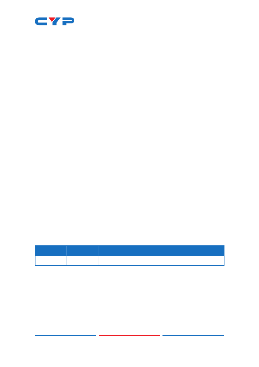
CYP CSC-5501 User manual

CSC-5501
HDMI/DP/VGA to Dual HDMI Scaler
Operation Manual
Operation Manual


DISCLAIMERS
The information in this manual has been carefully checked and
is believed to be accurate. Cypress Technology assumes no
responsibility for any infringements of patents or other rights of third
parties which may result from its use.
Cypress Technology assumes no responsibility for any inaccuracies
that may be contained in this document. Cypress also makes no
commitment to update or to keep current the information contained
in this document.
Cypress Technology reserves the right to make improvements to this
document and/or product at any time and without notice.
COPYRIGHT NOTICE
No part of this document may be reproduced, transmitted,
transcribed, stored in a retrieval system, or any of its part translated
into any language or computer le, in any form or by any means—
electronic, mechanical, magnetic, optical, chemical, manual, or
otherwise—without express written permission and consent from
Cypress Technology.
© Copyright 2018 by Cypress Technology.
All Rights Reserved.
TRADEMARK ACKNOWLEDGMENTS
All products or service names mentioned in this document are
trademarks of the companies with which they are associated.

SAFETY PRECAUTIONS
Please read all instructions before attempting to unpack, install or
operate this equipment and before connecting the power supply.
Please keep the following in mind as you unpack and install this
equipment:
• Always follow basic safety precautions to reduce the risk of re,
electrical shock and injury to persons.
• To prevent re or shock hazard, do not expose the unit to rain,
moisture or install this product near water.
• Never spill liquid of any kind on or into this product.
• Never push an object of any kind into this product through any
openings or empty slots in the unit, as you may damage parts
inside the unit.
• Do not attach the power supply cabling to building surfaces.
• Use only the supplied power supply unit (PSU). Do not use the PSU
if it is damaged.
• Do not allow anything to rest on the power cabling or allow any
weight to be placed upon it or any person walk on it.
• To protect the unit from overheating, do not block any vents or
openings in the unit housing that provide ventilation and allow for
sufcient space for air to circulate around the unit.
• Please completely disconnect the power when the unit is not in
use to avoid wasting electricity.
VERSION HISTORY
REVISION DATE SUMMARY OF CHANGE
VS1 09/11/18 Final technical review

CONTENTS
1. Introduction......................................................1
2. Applications.....................................................1
3. Package Contents ..........................................1
4. System Requirements......................................2
5. Features............................................................2
6. Operation Controls and Functions.................3
6.1 Front Panel ................................................. 3
6.2 Rear Panel.................................................. 4
6.3 Remote Control......................................... 5
6.4 OSD Menu.................................................. 6
6.5 WebGUI Control ...................................... 21
6.6.1 Main Page 0 ................................... 22
6.6.2 Main Page 1 ................................... 24
6.6 RS-232 Control ......................................... 26
6.7 Telnet Control .......................................... 26
6.8 RS-232 and Telnet Commands .............. 27
7. Connection Diagram ....................................46
8. Specications ................................................47
8.1 Technical Specications ........................ 47
8.2 Video Specications............................... 48
8.3 Audio Specications............................... 49
8.4 Cable Specications .............................. 50
9. Acronyms .......................................................51

1
1. INTRODUCTION
This Multi-Format Scaler has DisplayPort, HDMI and PC (VGA) inputs
which can be freely selected for output at a scaled resolution of the
user’s choosing over the mirrored HDMI outputs. This unit also includes
breakout analog and digital audio outputs to provide additional
playback exibility. Support for HDMI output resolutions up to 1080p/
WUXGA (RB) and Analog to Digital Conversion (ADC) functionality
combine to allow for a wide range of AV signals to be displayed on
the connected HDMI displays.
Beyond video switching and scaling, this unit also features useful audio
functions. An integrated audio DSP with gain control for routing audio
and controlling background audio levels (LPCM 2.0 only) adds to the
versatility of this product. This unit can be controlled via front panel
buttons with an On-Screen Display (OSD), WebGUI, Telnet, and RS-232
making it exceptionally versatile.
2. APPLICATIONS
• Analog and Digital source integration
• Upscaling standard denition sources for high-denition displays
• Conference centers
• Lecture halls
• Schools and universities
3. PACKAGE CONTENTS
• 1×HDMI/DP/VGA to Dual HDMI Scaler
• 1×24V/2.7A DC Power Adapter
• 1×Power Cord
• 1×Remote Control (CR-176)
• 1×Operation Manual

2
4. SYSTEM REQUIREMENTS
• HDMI, DisplayPort or VGA source equipment such as media players,
video game consoles, PCs, or set-top boxes.
• HDMI receiving equipment such as HDTVs, monitors or audio
ampliers.
• The use of “Premium High Speed HDMI” cables is highly
recommended.
5. FEATURES
• HDMI 1.3, DisplayPort 1.1, and DVI 1.0 compatible
• HDCP 1.x compliant
• Multiple video and audio inputs: 1 DisplayPort, 2 HDMI, 2 VGA, and
3 stereo audio
• Mirrored HDMI outputs
• Supports input and output resolutions up to 1080p/WUXGA (RB)
• Frame rate conversion support
• Analog to digital (ADC) and digital to analog (DAC) audio
conversion, insertion and extraction
• Analog stereo and digital coaxial breakout audio outputs
• Supports pass-through of LPCM 2.0 audio
• Audio DSP with gain control for routing audio and controlling
background audio levels
• Comprehensive EDID and HDCP management
• Remote control provides discrete input source selection
• Controllable via front panel controls with OSD, RS-232, Telnet,
WebGUI, and IR remote

3
6. OPERATION CONTROLS AND FUNCTIONS
6.1 Front Panel
1122
POWERDP HDMIVGA
MENU– +ENTER
XGA
720P
Multi-Format to HDMI Scaler
1 2 3 54 6
1POWER Button & LED: Press this button to power the unit on (Green
LED) or place it into stand-by mode (Red LED).
2IR Window: Accepts IR signals from the included IR remote for
control of this unit only.
3DP/HDMI 1~2/VGA 1~2 Buttons & LEDs: Press any of these buttons
to switch immediately to the corresponding input. An LED will
illuminate to indicate which source is currently selected.
4MENU Button: Press to enter the OSD menu, or to back out from
menu items.
Note: Pressing and holding the “MENU” button while connecting
the power supply will reset all settings to the factory defaults.
Pressing “MENU” and “+” together will reset the output resolution to
XGA (1024×768@60Hz). Pressing “Menu” and “−“ together will reset
the output resolution to 720p@60Hz.
5 − (MINUS) & + (PLUS) Buttons: Press to move up and down or adjust
selections within menus.
Note: When not in the OSD, pressing “−” will activate the Auto
Adjust function for VGA sources. Pressing “+” will briey show the
OSD information display.
6ENTER Button: Press to conrm a selection within the OSD or to go
deeper into a menu item.

4
6.2 Rear Panel
CONTROL
SERVICE RS-232
INPUT OUTPUT
HDMI BHDMI A
AUDIOAUDIOCOAX
DC 24V
12
3
HDMI
DP 1122
AUDIO
VGA
1
2
3
4
V+
GND
GND GND
V+
621
34 5
1DP INPUT Port: Connect to DisplayPort source equipment such as a
PC or laptop.
Note: In some rare cases, digital DisplayPort audio can’t be
supported. In those cases, please use analog audio input 1.
HDMI INPUT 1~2 Ports: Connect to HDMI source equipment such as
media players, game consoles or set-top boxes.
VGA INPUT 1~2 Ports: Connect to VGA source equipment such as
PCs or laptops.
AUDIO INPUT 1~3 Ports: Connect to the stereo analog outputs of
devices such as CD players or PCs.
Note: In “Audio Follows Video” mode, Audio 1 maps to the digital
inputs (DisplayPort, HDMI 1 & HDMI 2), Audio 2 maps to VGA 1 and
Audio 3 maps to VGA 2.
2HDMI A~B OUTPUT Ports: Connect to HDMI TVs, monitors or
ampliers for digital video and audio output.
Note: Both outputs carry the same video and audio content.
AUDIO 1~2 OUTPUT Ports: Connect to powered speakers or an
amplier for stereo analog audio output.
Note: Both outputs carry the same audio content.
COAX OUTPUT Port: Connect to powered speakers or an amplier
for digital audio output using an appropriate coaxial cable.
3SERVICE Port: This slot is reserved for rmware update use only.
4RS-232 Port: Connect directly to a PC, laptop or other serial control
device to send RS-232 commands to control the unit.

5
5CONTROL Port: Connect directly, or through a network switch, to
your PC/laptop to control the unit via Telnet/WebGUI.
6DC 24V Port: Plug the 24V DC power adapter into this port and
connect it to an AC wall outlet for power.
6.3 Remote Control
1POWER: Press this button to power the unit
on or place it into stand-by mode.
2DP/HDMI 1~2/PC 1~2: Press any of these
buttons to switch immediately to the
corresponding input.
3MENU: Press this button to enter the OSD
menu.
4EXIT: Press this button to exit the menu or
the current selection in the OSD menu.
5 OK/▲/▼/◄/► & VOL/−/+: Press OK to
conrm the selection or press the arrow
buttons to navigate the OSD menu. When
the OSD menu is not active, use the LEFT/
RIGHT (◄/►) buttons to control the volume
level.
6AUTO ADJUST: Press this button to activate the Auto Adjust function
for VGA sources.
7RESET: Press this button to reset the device back to the default
settings.
CR-176
OK
POWER
PC 1PC 2
HDMI 1HDMI 2DP
+
-
VOL
EXIT
RESET
MENU
AUTO
ADJUST
1
2
34
7
5
6

6
6.4 OSD Menu
All functions of this unit can be controlled by using the OSD (On
Screen Display) which is activated by pressing the MENU button on
the front of the unit. Use the + (PLUS), − (MINUS), and ENTER buttons to
navigate the OSD menu. Press the MENU button to back out from any
menu item and then press it again to close the menu.
MAIN MENU
Video
Picture
Audio
OSD
Ethernet
EDID
Reset
FW Update
Information
The individual functions of the OSD will be introduced in the following
section. Items marked in BOLD are the factory default settings.
VIDEO
2ND LEVEL 3RD LEVEL 4TH LEVEL
Video Routing DP
HDMI1
HDMI2
VGA1
VGA2
Output Native - HDMI B
Native - HDMI A
640×480 60
800×600 60
1024×768 60

7
VIDEO
2ND LEVEL 3RD LEVEL 4TH LEVEL
Output 1280×768 60
1360×768 60
1280×720 60
1280×800 60
1280×1024 60
1440×900 60
1400×1050 60
1680×1050 60
1600×1200 60
1920×1080 60
1920×1200 60
720×480p 60
1280×720p 60
1920×1080P 60
720×576p 50
1280×720p 50
1920×1080p 50
1920×1080p 24
1920×1080p 25
1920×1080p 30
Aspect Overscan
FULL
Best Fit
Pan Scan
Letterbox
Under 2
Under 1
Follow In

8
VIDEO
2ND LEVEL 3RD LEVEL 4TH LEVEL
DP HDCP Off
Refer To Source
REFER TO DISPLAY
HDMI1 HDCP Off
Refer To Source
REFER TO DISPLAY
HDMI2 HDCP Off
Refer To Source
REFER TO DISPLAY
No Signal Color BLACK
White
Blue
Red
Green
Blank OFF
On
Freeze OFF
On
Auto Setup Auto Sync Off OFF
30s
60s
3 Min
5 Min
10 Min
Auto Scan OFF
On
From DP
From HDMI1

9
VIDEO
2ND LEVEL 3RD LEVEL 4TH LEVEL
Auto Setup Auto Scan From HDMI2
From VGA1
From VGA2
Auto Switch OFF
On
VGA Setup Auto Setup [Current Status]
H Position 0 ~ 250
V Position 0 ~ 250
Phase 0 ~ 250
Clock 0 ~ 250 (125)
Reset
1) Video Routing: Selects the input source to display.
2) Output: Selects the output resolution to use. Selecting Native- HDMI
A or Native-HDMI B will make the unit automatically select an
output resolution based on the detected EDID of the connected
display.
3) Aspect: Selects the aspect ratio to use when outputting the source.
“Full” stretches the source to ll the output resolution, regardless
of the original aspect ratio, while “Best Fit” will always attempt to
retain the original source’s correct aspect ratio by adding black
bars if necessary. “Follow In” centers the source on the screen,
without any scaling (1:1 pixel reproduction).
4) DP HDCP: Selects the HDCP logic to use with the DisplayPort input.
Setting this to “Off” will completely disable HDCP support on that
input.
5) HDMI1 HDCP: Selects the HDCP logic to use with HDMI input 1.
Setting this to “Off” will completely disable HDCP support on that
input.
6) HDMI2 HDCP: Selects the HDCP logic to use with HDMI input 2.
Setting this to “Off” will completely disable HDCP support on that
input.

10
7) No Signal Color: Selects the free run color to use when no live input
source is detected.
8) Blank: Allows for the output video and audio to be blanked/
muted.
9) Freeze: Allows for the output video to be frozen. While the output is
frozen, audio output will also be muted.
10) Auto Setup [submenu]
■ Auto Sync Off: Sets the amount of time to continue outputting
sync with the free run color if there is no live source and no
operations have been executed on the unit. Setting this to “OFF”
forces the unit to always output sync.
■ Auto Scan: Enable or disable the auto scan on source loss
feature. Selecting a specic input will force the search to begin
with that input.
■ Auto Switch: Enable or disable automatically switching to any
newly detected source.
11) VGA Setup: These settings control the input specications to use
with the VGA inputs. Activating the Auto Setup function forces the
unit to attempt to detect the correct values. Selecting reset will
reset all VGA input settings.
Note: The "Auto Setup" function requires a VGA source with a
bright, edge-to-edge, image to accurately judge the dimensions
of the signal.
PICTURE
2ND LEVEL 3RD LEVEL
Color Gain R 0 ~ 1023 (512)
Color Gain G 0 ~ 1023 (512)
Color Gain B 0 ~ 1023 (512)
Color Offset R 0 ~ 1023 (512)
Color Offset G 0 ~ 1023 (512)
Color Offset B 0 ~ 1023 (512)
Brightness 0 ~ 60 (30)
Contrast 0 ~ 60 (30)
Hue 0 ~ 60 (30)

11
PICTURE
2ND LEVEL 3RD LEVEL
Saturation 0 ~ 60 (30)
Sharpness 0 ~ 63 (0)
NR OFF
Low
Middle
High
Auto
Reset Picture
1) Color Gain R/G/B: These controls provide control over the red,
green, and blue color gain level of the scaled output.
2) Color Offset R/G/B: These controls provide control over the red,
green, and blue color offset level of the scaled output.
3) Brightness: Provides control over the overall brightness of the
scaled output image.
4) Contrast: Provides control over the overall contrast of the scaled
output image.
5) Hue: Provides control over the hue shift of the scaled output
image.
6) Saturation: Provides control over the color saturation level of the
scaled output image.
7) Sharpness: Provides control over the amount of sharpness
processing to apply to the scaled output image.
8) NR: Provides control over the aggressiveness of the digital noise
reduction processing when applied to the scaled output image.
Selecting “Off” disables all noise reduction processing.
9) Reset Picture: Selecting this will reset all picture settings back to
their factory defaults.

12
AUDIO
2ND LEVEL 3RD LEVEL
Audio Routing FOLLOW VIDEO
Audio 1
Audio 2
Audio 3
HDMI Volume 0 ~ 100 (80)
Coax Volume 0 ~ 100 (80)
Analog Volume 0 ~ 100 (80)
HDMI Mute OFF
On
Coax Mute OFF
On
Analog Mute OFF
On
Audio Delay OFF
30ms
40ms
50ms
60ms
70ms
80ms
90ms
100ms
110ms
120ms
130ms
140ms
150ms
160ms

13
AUDIO
2ND LEVEL 3RD LEVEL
Audio Delay 170ms
180ms
190ms
200ms
HDMI Audio Delay Off
ON
Coax Audio Delay Off
ON
Analog Audio Delay Off
ON
Reset Audio
1) Audio Routing: Provides control over the analog audio routing
in the unit. Selecting “Follow Video” maps analog audio 1 to all
digital inputs (DisplayPort, HDMI 1 & HDMI 2), analog audio 2 to
VGA 1 and analog audio 3 to VGA 2. Selecting “Audio 1”, “Audio
2” or “Audio 3” will force the selected analog audio to be output
regardless of the selected video source.
Note: In “Follow Video” mode, digital inputs will only use the
analog audio if no digital audio is detected from the selected
source.
2) HDMI Volume: Provides control over both HDMI outputs’ volume
level.
3) Coax Volume: Provides control over the coaxial audio output’s
volume level.
4) Analog Volume: Provides control over both analog audio outputs’
volume level.
5) HDMI Mute: Mutes or unmutes both HDMI outputs’ audio.
6) Coax Mute: Mutes or unmutes the coaxial audio output.
7) Analog Mute: Mutes or unmutes both analog audio outputs.
8) Audio Delay: This control sets the amount of audio delay to use
when audio delay has been enabled on any audio output.

14
Selecting “Off” will disable audio delay for all output types.
9) HDMI Audio Delay: Enable or disable audio delay for the HDMI
outputs.
10) Coax Audio Delay: Enable or disable audio delay for the coaxial
audio output.
11) Analog Audio Delay: Enable or disable audio delay for the analog
audio output.
12) Reset Audio: Selecting this will reset all audio settings back to their
factory defaults.
OSD
2ND LEVEL 3RD LEVEL
H Position 0 ~ 60 (30)
V Position 0 ~ 60 (30)
Timer OFF
5s
10s
15s
20s
25s
30s
35s
40s
45s
50s
55s
60s
Transparent 0 ~ 50 (50)
Display Off
On
5S
10s

15
OSD
2ND LEVEL 3RD LEVEL
Reset OSD
1) H Position: Set the horizontal position of the OSD menu.
2) V Position: Set the vertical position of the OSD menu.
3) Timer: Set the length of time to wait before automatically turning
off the OSD menu if there is no user interaction. The timer may also
be disabled.
4) Transparent: Set the transparency level of the OSD menu. A setting
of 50 is completely opaque.
5) Display: Enable or disable the information display and set the
length of time for the information display to be visible after a
source or resolution change.
6) Reset OSD: Selecting this will reset all OSD settings back to their
factory defaults.
ETHERNET
2ND LEVEL 3RD LEVEL
IP Mode STATIC
DHCP
Telnet Login OFF
On
Setup Static IP Static IP: 192.168.1.50
Mask: 255.255.255.0
Gate: 192.168.1.254
IP [Current Status]
MAC
1) IP Mode: Select the IP address acquisition mode. When the unit
is set to DHCP mode it will attempt to automatically obtain an IP
address from a DHCP server. When set to Static mode the unit will
use the user dened static IP information.
2) Telnet Login: Enable or disable requiring a login to control the unit
via Telnet.
Table of contents
Other CYP Media Converter manuals