CYP CDPS-84HB User manual

CDPS-84HB
8 by 4 Digital Presentation Scaler
Operation Manual
Operation Manual

DISCLAIMERS
The information in this manual has been carefully checked and
is believed to be accurate. Cypress Technology assumes no
responsibility for any infringements of patents or other rights of third
parties which may result from its use.
Cypress Technology assumes no responsibility for any inaccuracies
that may be contained in this document. Cypress also makes no
commitment to update or to keep current the information contained
in this document.
Cypress Technology reserves the right to make improvements to this
document and/or product at any time and without notice.
COPYRIGHT NOTICE
No part of this document may be reproduced, transmitted,
transcribed, stored in a retrieval system, or any of its part translated
into any language or computer le, in any form or by any means—
electronic, mechanical, magnetic, optical, chemical, manual, or
otherwise—without express written permission and consent from
Cypress Technology.
© Copyright 2012 by Cypress Technology.
All Rights Reserved.
Version 1.0 October 2009
TRADEMARK ACKNOWLEDGMENTS
All products or service names mentioned in this document may be
trademarks of the companies with which they are associated.

SAFETY PRECAUTIONS
Please read all instructions before attempting to unpack, install or
operate this equipment and before connecting the power supply.
Please keep the following in mind as you unpack and install this
equipment:
• Always follow basic safety precautions to reduce the risk of re,
electrical shock and injury to persons.
• To prevent re or shock hazard, do not expose the unit to rain,
moisture or install this product near water.
• Never spill liquid of any kind on or into this product.
• Never push an object of any kind into this product through any
openings or empty slots in the unit, as you may damage parts
inside the unit.
• Do not attach the power supply cabling to building surfaces.
• Use only the supplied power supply unit (PSU). Do not use the PSU
if it is damaged.
• Do not allow anything to rest on the power cabling or allow any
weight to be placed upon it or any person walk on it.
• To protect the unit from overheating, do not block any vents or
openings in the unit housing that provide ventilation and allow for
sufcient space for air to circulate around the unit.
REVISION HISTORY
VERSION NO. DATE DD/MM/YY SUMMARY OF CHANGE
RDV1 05/05/14 Preliminary Release
RDV2 09/15/14 Add RS-232 Commands

CONTENTS
1. Introduction............................................ 1
2. Applications........................................... 1
3. Package Contents ................................ 1
4. System Requirements............................ 1
5. Features.................................................. 2
6. Operation Controls and Functions....... 3
6.1 Front Panel ........................................3
6.2 Rear Panel.........................................4
6.3 Remote Control ...............................5
6.4 IR Pin Assignment .............................6
6.5 RS-232 Pin Assignment .....................7
6.6 RS-232/Telnet Commands...............8
6.7 OSD Menu.......................................11
7. Connection Diagram .......................... 15
8. Specications ...................................... 16
8.1 Input Resolution Support ...............17
8.2 Output Resolution Support ...........18
9. Acronyms ............................................. 19

1
1. INTRODUCTION
This HDBaseT™ capable 8 by 4 Digital Presentation Scaler can switch
and scale HDMI/HDBaseT/PC/Composite Video signals from any one
of its eight inputs and simultaneously display it on any of its HMDI or
HDBaseT outputs. The unit has and HDMI bypass output, allowing local
monitoring of any of the HDMI or HDBaseT inputs, and features full
5play™ convergence for easy integration of compatible transmitters
and receivers. It has the added benet of control via IR remote
control, RS-232, IP/Telnet and WebGUI, with all information including
system status presented on its comprehensive LCD display.
2. APPLICATIONS
• Home Theater/Entertainment
• Lecture Room/Hall Presentation
• Show Room/Demo Room
• Public Commercial Display
• Information Board
3. PACKAGE CONTENTS
• 1 x 8 by 4 Presentation Scaler
• 1 x IR Extender Cable
• 1 x IR Receiver Cable
• 1 x Remote Control with Battery
• 1 x 24V/ 2.7A DC Power Adaptor
• 1 x Power Cord
• Operation Manual
4. SYSTEM REQUIREMENTS
Input source equipment such as Blu-ray/DVD/PS3 player or Set-Top-Box
and output HDMI TV/Display and or audio amplier with connection
cables.

2
5. FEATURES
• HDMI, HDCP and DVI compliant
• Full 5Play™ convergence: Video, Audio, LAN serving, Power over
Cable (PoC) and Control (IR & RS-232 bypass)
• Supports distances of up to 100 meters over industry standard
CAT5e/6/7 cable
• Supports scaling of any input signals to a wide range of HDTV and
PC output resolutions up to 1080p and WUXGA (RB)
• Digital to Analog and Analog to Digital Audio conversion (DAC/
ADC)
• Simultaneous video output of the selected source through the
HDBaseT and HDMI outputs and audio output through the digital
coaxial and analog L/R outputs
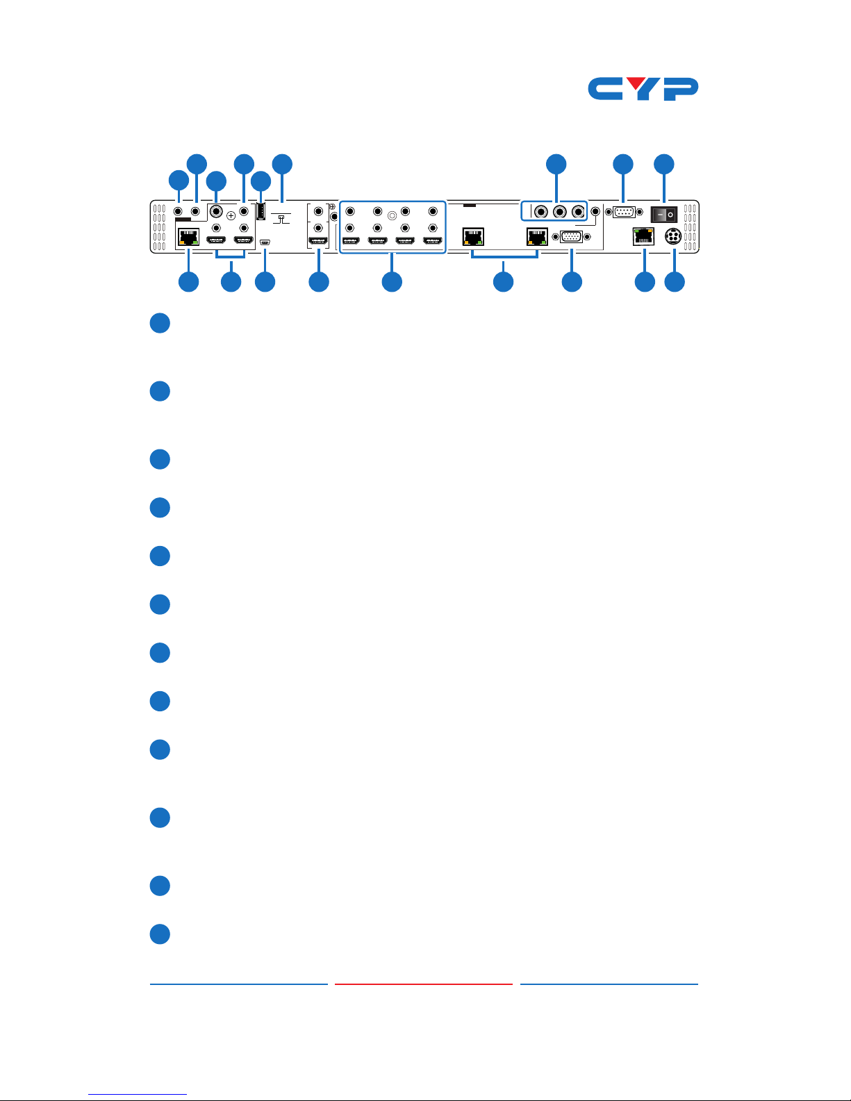
• Features four HDMI inputs with corresponding L/R audio inputs
(3.5mm mini-jack), two HDBaseT CAT5e/6/7 inputs, PC (15-pin D-Sub)
with L/R audio (3.5mm mini-jack) and Composite Video and L/R
audio (3 RCA)
• Features two HDMI outputs, one HDBaseT CAT5e/67 outputs, one
Digital Coaxial audio output and one L/R audio 3.5mm mini-jack
output
• Supports switchable HDMI bypass allowing local monitoring of any
of the HDMI or HDBaseT inputs
• Supports Power over Cable on the CAT5e/6/7 output to a
compatible Receiver
• Supports control via IR, Remote control, RS-232, Telnet WebGUI and
on-panel controls
• Supports HDBaseT LAN serving function to compatible Receivers
Note: The PoC function is only designed for powering compatible
Receiver units only---non-PoC Receiver will need their own
power supply. Receivers of another brand may not be
compatible.

3
6. OPERATION CONTROLS AND FUNCTIONS
6.1 Front Panel
1 2 3 65 7 8 9 10 3
4 4
65 7
1POWER: Press this button to turn ON the device and the LED will
illuminated.
2IR Window: This IR receiver receives only the remote control signal
from the packaged included remote control.
3INPUT HDMI 1~4 & LED: Press the IN buttons to select an input source
signal from the 4 HDMI input sources to be display for output ports.
The LED will illuminate according to the selection.
4BYPASS & LED: Press these buttons to select an input source signal
from the 6 input sources to be display for BYPASS output port. The
LED will illuminate according to the selection.
5INPUT CAT5e/6/7 5~6 & LED: Press the IN buttons to select an input
source signal from the 2 CAT5e/6/7 input sources to be display for
output ports. The LED will illuminate according to the selection.
6INPUT PC & LED: Press this button to select PC input source signal to
be display for PC output port. The LED will illuminate according to
the selection.
7INPUT CV & LED: Press this button to select CV input source signal s
to be display for CV output port. The LED will illuminate according
to the selection.
8MENU: Press this wheel to enter into the menu and press it again to
conrm the selection.
9+/-: Press these buttons to move up/down under menu selection or
under volume control to adjust audio volume up/down.
10 ENTER: Press this button to conrm menu selection.

4
6.2 Rear Panel
IR IN
HDMI 1HDMI 2
SERVICE 2
COAX
AUDIO
AUDIO AUDIO 7AUDIO 1 AUDIO 2 AUDIO 3 AUDIO 4
HDMI
BYPASS
CAT5e/6/7CAT5e/6/7 CAT5e/6/7 PC
HDMI 1 HDMI 2HDMI 3HDMI 45 67
INPUT RLCV
8
LAN
RS-232
DC 24 V
OUTPUT
IR OUT
SERVICE 1
ON OFF
DSP PROG.
1
2 6 8 13 14 16
5 7
3 4 7 9 10 12 15 1711
1IR OUT: Connect to the supplied IR Blaster cable for IR signal
transmission. Place the IR Blaster in direct line-of-sight of the
equipment to be controlled.
2IR IN: Connect to the supplied IR Extender cable for IR signal
reception. Ensure that remote being used is within the direct line-
of-sight of the IR Extender.
3OUTPUT CAT5e/6/7: Connect to the Receiver unit with a Single
CAT5e/6/7 cable for transmission of all data signals.
4OUTPUT HDMI: Connect to a HDMI equipped TV/monitor for display
of the HDMI input source signal.
5OUTPUT COAX: Connect to audio sound equipment such as
speaker or amplier for audio sound output.
6OUTPUT AUDIO: Connect to audio sound equipment such as
speaker or amplier for audio sound output.
7SERVICE 1& 2: These slots are reserved for rmware update use
only.
8DSP PROG Switch: This switch is reserved for rmware update use
only. Default setting is on OFF.
9BYPASS: Connect to a HDMI equipped TV/monitor or DVI equipped
monitor with audio sound equipment such as speaker for both
video and audio output display.
10 INPUT HDMI 1~4 & AUDIO 1~4: Connect to HDMI source equipment
such as DVD or Blu-ray player along or to DVI source equipment
along with audio source signal.
11 INPUT CAT5e/6/7: Connect this port to HDMI to CAT5e/6/7
Transmitter with CAT5e/6/7 cable to extend the signal up to 100m.
12 INPUT PC & AUDIO: Connect this port to PC/Laptop with audio
signal for input signal selecting.

5
13 INPUT CV: Connect this port to source equipment such as video
player or Set-Top-Box for input signal selecting.
14 RS-232: Connect from PC/Laptop for RS-232 command sending to
control the device.
15 LAN: Connect from PC/Laptop with active internet service for Web
GUI control with RJ-45 terminated cable.
16 POWER Toggle: Switch this toggle to turn ON and OFF the device’s
power.
17 DC 24V: Connect the adaptor with power cord included in the
package and connect to AC wall outlet for power supply.
6.3 Remote Control
1POWER:
Press this button to switch the device
ON or to put the device into Standby
mode.
2MUTE:
Press this button to mute output audio
sound.
3INPUT:
Press these buttons one time each
to select input source for outputs
display.
4MENU:
Press this button to enter into the On-
Screen Menu.
5EXIT:
Press this button to exit menu
selection.
6 ▲▼◄►& OK:
Press OK to conrm the selection
or use the directional buttons to
navigate the On-Screen-Menu.
MUTE
CAT5e/6/7
POWER
EXIT MENU
RESET ADJUST
-
+
CR-135
OK
HDMI 1 CAT5e/6/7 1
HDMI 2
HDMI 3
CAT5e/6/7 2
HDMI 4
HDMI 4
HDMI 1 1PC
HDMI 2 2CV
HDMI 3
INPUT
BYPASS
12
5
8
3
9
4
7
6

6
7ADJUST:
Press this button when output image is not tting the display's
screen perfectly. The device will auto adjust the image to full
screen.
8RESET:
Press this button to set the deivice back into the fatory default
setting.
9BYPASS:
Press these buttons to select an input source for Bypass output port
to display.
6.4 IR Pin Assignment
3
1
3
1
2
2
Power
IR Blaster Signal
NC
IR Signal
Power
Grounding
IR Receiver
IR Blaster

7
6.5 RS-232 Pin Assignment
CDPS-84HB
►
◄
Remote Control
PIN Assignment PIN Assignment
1 NC 1 NC
2Tx 2Rx
3Rx 3Tx
4 NC 4 NC
5 GND 5 GND
6 NC 6 NC
7 NC 7 NC
8 NC 8 NC
9 NC 9 NC
Baud Rate: 19200bps
Data Bit: 8 bits
Parity: None
Flow Control: None
Stop Bit: 1

8
6.6 RS-232/Telnet Commands
COMMAND DESCRIPTION
S SOURCE 1~8 1=HDMI 1
2=HDMI 2
3=HDMI 3
4=HDMI 4
5=HDBT 1
6=HDBT 2
7=PC
8=VIDEO
R SOURCE Reports the numerical equivalent for SOURCE
setting (as above)
S OUTPUT 0~21 0=640×480
1=800×600
2=1024×768
3=1280×768
4=1360×768
5=1280×720
6=1280×800
7=1280×1024
8=1440×900
9=1400×1050
10=1680×1050
11=1600×1200
12=1920×1080
13=1920×1200
14=480p
15=720p@60
16=1080i@60
17=1080p@60
18=576p
19=720p@50
20=1080i@50
21=1080p@50
R OUTPUT Reports the numerical equivalent for OUTPUT
setting (as above)
S SIZE 0~6 0=OVERSCAN
1=FULL
2=FOLLOW INPUT
3=PAN SCAN
4=LETTER BOX
5=UNDER 2
6=UNDER 1
R SIZE Reports the numerical equivalent for SIZE
setting (as above)
S INPUTHDCP 0/1
R INPUTHDCP
0=OFF 1=ON
Reports HDMI support HDCP status
S CONTRAST 0~60 Setups the numerical equivalent for
CONTRAST setting (as left)
R CONTRAST Reports the numerical equivalent for
CONTRAST setting
S BRIGHTNESS 0~60 Setups the numerical equivalent for
BRIGHTNESS setting (as left)

9
COMMAND DESCRIPTION
R BRIGHTNESS Reports the numerical equivalent for
BRIGHTNESS setting
S HUE 0~60 Setups the numerical equivalent for HUE
setting (as left)
R HUE Reports the numerical equivalent for HUE
setting
S SATURATION 0~60 Setups the numerical equivalent for
SATURATION setting (as left)
R SATURATION Reports the numerical equivalent for
SATURATION setting
S SHARPNESS 0~30 Setups the numerical equivalent for
SHARPNESS setting (as left)
R SHARPNESS Reports the numerical equivalent for
SHARPNESS setting
S NR 0~3 0=OFF
1=LOW
2=MIDDLE
3=HIGH
R NR Reports the numerical equivalent for the
NOISE REDUCTION setting (as above)
S VOLUME 0~100
R VOLUME
Volume Value
Reports Volume value
S AUDIO DELAY 0~3 0=OFF
1=40ms
2=110ms
3=150ms
R AUDIO DELAY Reports the numeric equivalent for AUDIO
DELAY setting (as above)
S AUDIO MUTE 0/1 0=ON 1=MUTE
R AUDIO MUTE Reports the numeric equivalent for AUDIO
MUTE setting (as above)
S HDMIAUDIO 0/1 0=AUTO
1=EXT.
R HDMIAUDIO Reports HDMI AUDIO Status
S KEY LOCK 0/1 0=Disable 1=Enable
R KEY LOCK Reports the numeric equivalent for KEY
LOCK setting (as above)
S FREERUNCOLOR 0/1 0=Black 1=Blue
R FREERUNCOLOR Reports the numeric equivalent for FREERUN
Colorsetting (as above)

10
COMMAND DESCRIPTION
S HDBTUART 0/1 0=HDBT1 1=HDBT2
R HDBTUART Reports the numeric equivalent for HDBT
UART setting (as above)
S AUTO SCAN 0/1 0=OFF 1=ON
R AUTO SCAN Reports the numeric equivalent for AUTO
SCAN setting (as above)
S BYPASS 1~6
R BYPASS
1=HDMI 1
4=HDMI 4
1=HDMI 2
5=HDBT 1
3=HDMI 3
6=HDBT2
Reports the numeric equivalent for BYPASS
setting (as above)
S RESET 1 Setups the numerical equivalent for RESET
setting (as left)
S POWER 0/1 0=OFF 1=ON
R POWER Reports the numeric equivalent for POWER
setting (as above)
PORT 0~8 1=HDMI
4=HDMI 4
7=PC
2=HDMI 2
5=HDBT 1
3=HDMI 3
6=HDBT 2
8=VIDEO 0=Last Memory
VOL +
VOL -
Volume Value
Volume Value
ST FW Version & Source
Note:
1. Only LPCM 2 channel digital audio is supported, please ensure
that the source audio is set to LPCM 2 channel audio in order to
avoid unnecessary audio noise.
2. RS-232 commands will be not executed unless followed with a
carriage return and LF. Commands are case-insensitive.

11
6.7 OSD Menu
1st Layer 2nd Layer 3rd Layer Remark
DISPLAY OUTPUT 640X480 60
800x600 60
1024x768 60
1280x768 60
1360x768 60
1280x720 60
1280x800 60
1280x1024 60
1440x900 60
1400x1050 60
1680x1050 60
1600x1200 60
1920x1080 60
1920x1200 60
720X480P 60
1280X720P 60
1920X1080I 60
1920X1080P 60
720X576P 50
1280X720P 50
1920X1080I 50
1920X1080P 50

12
DISPLAY SIZE OVER SCAN
FULL
FOLLOW INPUT
PAN SCAN
LETTER BOX
UNDER 2
UNDER 1
MODE INFO OFF
INFO
ON
INPUT HDCP
(HDMI mode
only)
OFF
ON
PC
(PC mode
only)
AUTO SETUP Yes/No(Default No)
H_POSITION 0~60
V_POSITION 0~60
PHASE 0~31
CLOCK
WXGA/XGA XGA/WXGA(Default
XGA)
RESET Yes/No(Default No)

13
COLOR CONTRAST 0~60(Default 30)
BRIGHTNESS 0~60(Default 30)
COLOR R 0~1023(Default 512)
G 0~1023(Default 512)
B 0~1023(Default 512)
R OFFSET 0~1023(Default 512)
G OFFSET 0~1023(Default 512)
B OFFSET 0~1023(Default 512)
HUE 0~60(Default 30)
SATURATION 0~60(Default 30)
SHARPNESS 0~30(Default 0)
NR. OFF
LOW
MIDDLE
HIGH
AUDIO VOLUME 0~100(Default 100)
DELAY OFF
40mS
110mS
150mS
SOUND ON
MUTE
SOURCE
(HDMI mode
only)
AUTO
EXT.

14
SETUP FACTORY RESET OSD Setting back to
factory default
KEY LOCK OFF
ON
POWER
SAVE
OFF
ON
IP MODE DHCP
STATIC
SET STATIC IP IP ADDRESS 0.0.0.0~
255.255.255.255
(Default 192.168.0.1)
SUBNET MASK 0.0.0.0~
255.255.255.255
(Default 255.255.255.0)
Def. GATWAY 0.0.0.0~
255.255.255.255
(Default 192.168.0.254)
FREERUN
COLOR
BLUE
BLOCK
MISC. HDBTOUT
(UART1)
HDBT1~2(Default
HDBT1)
Auto Scan OFF
ON
INFORMATION INPUT:
OUTPUT:
REVISION:
IP ADDRESS:
Default settings are underlined.

15
7. CONNECTION DIAGRAM
IR IN
HDMI 1 HDMI 2
SERVICE 2
COAX
AUDIO
AUDIO AUDIO 7AUDIO 1 AUDIO 2 AUDIO 3AUDIO 4
HDMI
BYPASS
CAT5e/6/7CAT5e/6/7 CAT5e/6/7PC
HDMI 1 HDMI 2 HDMI 3HDMI 45 67
INPUT RLCV
8
LAN
RS-232
DC 24 V
OUTPUT
IR OUT
SERVICE 1
ON OFF
DSP PROG.
HDMI HDMI 1 HDMI 2 HDMI 3HDMI 4 7
INPUT
CAT5e/6 In
Link
IR1 Extender
IR2 Blaster
Power
RX
RS-232In
LAN
HDMIIn
HDMIto CAT5e/6 with LAN/IR/RS232
Transmitter TX
IR BLASTER
1.5m
60°
IR Extender
7m
3m 3m
60°
m
Set-top Box
Active Speakers
Active
Speakers
Router with
Internet
Connection
RS-232
Equipped PC
RS-232
Cable
Power
Supply
Network
Router
PC
DELL PC/
Laptop
DVI to
HDMI
Output
HDMI
Input
Blu-ray
Player
Blu-ray or PS3 Player
HDMI
3D TV/
Display
3D TV/
Display
CAT5e/6
Output
100M
Blu-ray/DVD
Player
Smartphone
or Tablet
100M

16
8. SPECIFICATIONS
Frequency bandwidth Up to 10.2Gbps
Input Ports 4 x HDMI
4 x L/R
2 x CAT5e/6/7
1 x PC + L/R
1 x CV+L/R
2 x USB (Service only)
1 x LAN
1 x RS-232
1 x IR
Output ports 2 x HDMI
1 x HDMI Bypass
1 x CAT5e/6/7
1 x Coaxial
1 x L/R
Resolution 480i~1080p@50/60, 1080p@24,
VGA~WUXGA(RB)
Audio Format LPCM 2CH
ESD Protection Human body model:
±8kV (air-gap discharge)
±4kV (contact discharge)
Power Supply 24VDC/2.7A (US/EU standards, CE/FCC/
UL certied)
Dimensions 438mm (W) x 269mm (D) x 44mm (H)/Jack
Excluded
438mm (W) x 275mm (D) x 44mm (H)/Jack
Included
Weight 3410g
Chassis Material Metal
Silkscreen Color Black
Operating Temperature 0˚C~40˚C / 32˚F ~ 104˚F
Table of contents
Other CYP Media Converter manuals
Popular Media Converter manuals by other brands

Dedicated Micros
Dedicated Micros DV-IP Decoder Setup guide

Lindy
Lindy 32159 user manual

Baumer
Baumer ITD21H00-HT Installation and operating instruction

nedis
nedis HQ AVSPLIT-40 manual

Datalogic
Datalogic AMT58-S-16x14 FBUS Series Mounting instructions

Speaka Professional
Speaka Professional 1095853 operating instructions

Digitrax
Digitrax SDN144K1E user manual

GRASS VALLEY
GRASS VALLEY 8935CF - datasheet

Cross Technologies
Cross Technologies 2017-93 instruction manual

Siemens
Siemens SIMOVERT 6SE7024-1EB85-0AA0 operating instructions

IMC Networks
IMC Networks MediaConverter 1 Operation manual

Husqvarna
Husqvarna CF 11M Operator's manual