CYP CLUX-2HPIP User manual

CLUX-2HPIP
2×1 HDMI Multiviewer
Operation Manual
Operation Manual


DISCLAIMERS
The information in this manual has been carefully checked and
is believed to be accurate. Cypress Technology assumes no
responsibility for any infringements of patents or other rights of third
parties which may result from its use.
Cypress Technology assumes no responsibility for any inaccuracies
that may be contained in this document. Cypress also makes no
commitment to update or to keep current the information contained
in this document.
Cypress Technology reserves the right to make improvements to this
document and/or product at any time and without notice.
COPYRIGHT NOTICE
No part of this document may be reproduced, transmitted,
transcribed, stored in a retrieval system, or any of its part translated
into any language or computer le, in any form or by any means—
electronic, mechanical, magnetic, optical, chemical, manual, or
otherwise—without express written permission and consent from
Cypress Technology.
© Copyright 2018 by Cypress Technology.
All Rights Reserved.
TRADEMARK ACKNOWLEDGMENTS
All products or service names mentioned in this document may be
trademarks of the companies with which they are associated.

SAFETY PRECAUTIONS
Please read all instructions before attempting to unpack, install or
operate this equipment and before connecting the power supply.
Please keep the following in mind as you unpack and install this
equipment:
• Always follow basic safety precautions to reduce the risk of re,
electrical shock and injury to persons.
• To prevent re or shock hazard, do not expose the unit to rain,
moisture or install this product near water.
• Never spill liquid of any kind on or into this product.
• Never push an object of any kind into this product through any
openings or empty slots in the unit, as you may damage parts
inside the unit.
• Do not attach the power supply cabling to building surfaces.
• Use only the supplied power supply unit (PSU). Do not use the PSU
if it is damaged.
• Do not allow anything to rest on the power cabling or allow any
weight to be placed upon it or any person walk on it.
• To protect the unit from overheating, do not block any vents or
openings in the unit housing that provide ventilation and allow for
sufcient space for air to circulate around the unit.
REVISION HISTORY
VERSION NO. DATE SUMMARY OF CHANGE
RDV1 14/03/18 Preliminary release
VS1 01/06/18 Final technical review

CONTENTS
1. Introduction......................................................1
2. Applications.....................................................1
3. Package Contents ..........................................1
4. System Requirements......................................2
5. Features............................................................2
6. Operation Controls and Functions.................3
6.1 Front Panel ................................................. 3
6.2 Rear Panel.................................................. 4
6.3 WebGUI Control ........................................ 5
6.4 RS-232 Control ......................................... 15
6.5 Telnet Control .......................................... 15
6.6 RS-232 and Telnet Commands .............. 16
7. Connection Diagram ....................................31
8. Specications ................................................32
8.1 Technical Specications ........................ 32
8.2 Video Specications............................... 33
8.3 Audio Specications............................... 34
8.4 Cable Specications .............................. 35
9. Acronyms .......................................................35

1
1. INTRODUCTION
This HDMI Multiviewer is capable of scaling up to 2 sources and
displaying both simultaneously on a single HDMI output within
their own windows. This is the ideal solution for monitoring multiple
sources simultaneously for use in control rooms, or for exible display
presentations in conference rooms or classrooms. Both inputs support
resolutions up to 1920×1200@60Hz and LPCM audio with up to 7.1
channels at 192kHz.
The multi-window output is sent to a single HDMI output at scaled
resolutions up to 1920×1200@60Hz along with the selected audio
source. The HDMI output supports up to LPCM 7.1 digital audio while
the analog audio output supports up to LPCM 2.0. Each of the 2 HDMI
sources may be displayed individually, full screen, or they can be
displayed using a variety of dual-window modes including Picture-in-
Picture, Side-by-Side, or freely positioned (with layer priority control).
Each window can also be mirrored, ipped, swapped, or frozen (with
live audio). Chromakeying and a custom uploadable logo/graphic
are also supported.
By using an optional Windows PC application, the user can use their
PC to generate images or text to be overlaid on top of a live HDMI
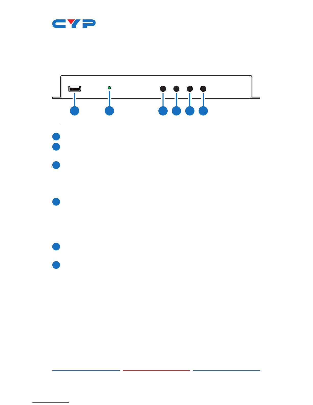
input in real time. This unit can be controlled easily by use of the front
panel controls (with OSD) as well as by WebGUI, Telnet, RS-232, IR, and
8 direct trigger inputs.
2. APPLICATIONS
• Demo Room Displays
• Security Monitoring
• Hotel Lobby Information Displays
3. PACKAGE CONTENTS
• 1×HDMI Multiviewer
• 1×5V/2.6A DC Power Adapter
• 3×5-pin Terminal Block
• 1×Shockproof Feet (Set of 4)
• 1×Operation Manual

2
4. SYSTEM REQUIREMENTS
• HDMI source equipment such as media players, video game
consoles or set-top boxes.
• HDMI receiving equipment such as an HDTV, monitor, or audio
amplier.
• Analog audio receiving equipment such as headphones, an audio
amplier or powered speakers.
5. FEATURES
• HDMI & HDCP 1.3 compliant
• 2 HDMI inputs and 1 HDMI output
• Inputs and output support HD resolutions up to 1080p@60Hz and PC
resolutions up to WUXGA (RB)
• Supports audio pass-through of LPCM 2.0/5.1/7.1 sources via HDMI
• Balanced analog stereo audio extraction support via 5-pin terminal
block (LPCM 2.0 only)
• Supports PiP (Picture-in-Picture), Side-by-Side, and free positioning
window modes
• Easy individual window size, position and layer priority adjustment
• Supports per-window mirror, ip, and image freeze (w/ live audio)
functionality
• Chromakey support
• Uploadable logo support
• Support for Windows PC character generation software to simplify
the process of generating text or graphics to use with keying/
overlay (Optional)
• 8 Trigger inputs for easy remote control of the unit with optional
keypad
• Supports front panel buttons (with OSD), WebGUI, Telnet, RS-232, IR,
and Trigger controls

3
6. OPERATION CONTROLS AND FUNCTIONS
6.1 Front Panel
SERVICE SWITCH MODE AUDIO INFO.
POWER
1 2 3 4 5 6
1SERVICE: This port is reserved for rmware update use only.
2POWER LED: This LED will illuminate to indicate the unit is on and
receiving power.
3SWITCH Button: Press to toggle between the two HDMI inputs and
output the selected source full screen.
Note: Press and hold this button for 2 seconds to change the
output resolution to 1920×1080p@60Hz.
4MODE Button: Press to sequentially switch between the Full Screen
(NONE), Picture-in-Picture (PIP), Side-by-Side (SBS), and Picture-
outside-Picture (POP) windowing modes.
Note: Press and hold this button for 2 seconds to change the
output resolution to 1024×768@60Hz.
5AUDIO Button: Press to toggle between the audio from the 2 HDMI
inputs.
6INFO. Button: Short press to show the current input/output resolution
status, audio selection and IP information. Long press to show the
current contrast, brightness, hue, sharpness, color format, chroma
and color temperature settings for each source channel.

4
6.2 Rear Panel
DC 5V
CONTROLRS-232TRIGGER IN
L R
-
-
++
OUT
AUDIO
2IN1
1 2 3 4 5 6 7
1AUDIO OUT: Connect to powered speakers or an amplier for
balanced stereo analog audio output.
2HDMI OUT: Connect to an HDMI TV, monitor or amplier for digital
video and audio output.
3TRIGGER IN: This 10 pin terminal block provides 8 trigger pins (plus
5V & Ground) for activating pre-designated functions within the
unit. Compatible with the optional Trigger Keypad unit.
Pins are numbered from left to right:
TOP ROW BOTTOM ROW
1Vcc (5V) 6GROUND
2POP Windowing Mode 7Image Freeze (Toggle)
3SBS Windowing Mode 8Display Logo (Toggle)
4PIP Windowing Mode 9A/V Mute (Toggle)
5Full Screen Window
(Toggle)
10 Window Source Swap
(Toggle)
4HDMI IN 1~2: Connect to HDMI source equipment such as media
players, game consoles or set-top boxes.
5RS-232: Connect directly to a PC, laptop or other serial control
device to send RS-232 commands to control the unit.
6CONTROL: Connect directly, or through a network switch, to your
PC/laptop to control the unit via Telnet/WebGUI.
7DC 5V: Plug the 5V DC power adapter into the unit and connect it
to an AC wall outlet for power.

5
6.3 WebGUI Control
• Device Discovery APP
Please obtain the “Device Discovery” software from your authorized
dealer and save it in a directory where you can easily nd it.
Connect the unit and your PC/Laptop to the same active network
and execute the “Device Discovery” software. Click on “Find Devices
on Network” and a list of devices connected to the local network will
show up indicating their current IP address.
Note: The unit’s default IP address is 192.168.1.50.
By clicking on one of the listed devices you will be presented with the
network details of that particular device.
1) IP Mode: If you choose, you can alter the static IP network settings
for the device, or switch the unit into DHCP mode to automatically
obtain proper network settings from a local DHCP server. To switch
to DHCP mode, please select DHCP from the IP mode drop-down,
then click “Save” followed by “Reboot”.
2) WebGUI Hotkey: Once you are satised with the network settings,
you may use them to connect via Telnet or WebGUI. The network
information window provides a convenient link to launch the
WebGUI directly.

6
• WebGUI Overview
After connecting to the WebGUI’s address in a web browser, the
login screen will appear. Please enter the appropriate user name and
password then click “Submit” to log in.
Note: The default user name and password is “admin”.
On the left side of the browser you will see the following menu
tabs where all primary functions of the unit are controllable via the
built in WebGUI: Adjustment, Windows Setup, OSD/LOGO Settings,
Chromakey Setup, Network, and System. The individual functions will
be introduced in the following sections.
Clicking the red “Logout” tab will automatically log the currently
connected user out of the WebGUI and return to login page.
• Information Bar
Across the top of the WebGUI are 5 sections that will always be
displayed no matter which tab has been selected. These sections are:
Information-In, Information-Out, Source, Mode, and Preset/Factory.
They provide information about the state of the unit, or control the
most basic functions of the unit.
1) Information-In: Provides the detected resolution information about
the source connected to each of the HDMI inputs.

7
2) Information-Out: Provides the unit’s current output resolution as
well as listing the current Window Mode.
3) Source: Provides controls for the A/V Mute function and Audio
Source selection.
■ A/V Mute: When A/V Mute is enabled, all output will be
disabled on the HDMI output.
■ Audio From CH: Select which HDMI input’s audio to pass to
both the HDMI and analog outputs.
Note: The analog output can only support LPCM 2.0 audio.
Bitstream audio will be automatically muted.
4) Mode: Provides controls for changing the Window Mode, swapping
window sources, changing window priority and selecting the input
in the “NONE” window mode.
■ Window Mode: Allows selecting the current windowing mode
from 4 choices: PIP (Picture-in-Picture), SBS (Side-by-Side),
POP (Picture-outside-Picture) and NONE (Full screen seamless
switcher).
Notes: The PIP, SBS, and POP modes will each recall their most
recently saved window sizes and positions, not their default
arrangements. Changing this setting when Chromakey is enabled
will automatically disable Chromakey mode.
■ Swap: Allows swapping the input channel between the
windows in the multi-windowing modes.
Note: Enabling Swap mode will also automatically switch the
Priority setting in order to maintain the existing Window display
priority.
■ Priority: Selects which input channel is on top in the multi-
windowing modes.
■ From Input: Selects the input to display when the unit is in the
“NONE” (Full screen seamless switcher) Windowing Mode.
5) Preset/Factory: Provides controls for saving and loading Presets
and for resetting the unit.
■ Preset Save/Recall: This unit can store and recall up to four
presets. Each preset stores the settings from the Mode, Contrast,
Brightness, Sharpness, Hue, image Still, Flip, and Upside-Down
sections of the WebGUI for rapid, hassle-free, recall.

8
Note:Theoutputwillbrieygoblackduringthepresetrecall
process.
■ Factory Reset: Click on the Factory Reset button to reset the
unit to its factory default state. After the reset is complete, the
unit will reboot automatically.
Note:Networkcongurationdetailswillnotbereset.
• Adjustment Tab
This tab provides controls over the general display characteristics of
each input channel as well as providing a way to set the unit’s output
resolution.
1) Contrast: Sets the contrast level for each input channel with a
range of 0 to 100. Clicking on the slider will allow ne adjustments
using the arrow keys. The default value is 80.
2) Brightness: Sets the brightness level for each input channel with a
range of 0 to 100. Clicking on the slider will allow ne adjustments
using the arrow keys. The default value is 50.
3) Sharpness: Sets the amount of sharpness processing to apply to
each input channel with a range of 0 to 20. Clicking on the slider
will allow ne adjustments using the arrow keys. The default value is
10.
4) Hue: Sets the hue value for each input channel with a range of 0
to 100. Clicking on the slider will allow ne adjustments using the
arrow keys. The default value is 50.
5) Output Resolution: Sets the unit’s output resolution. The default
selection is 1080p60.

9
6) Image Still: Freezes and unfreezes the video from the selected
input channel. This function is off by default.
7) Flip: Enabling the Flip function will cause the video in the selected
input channel to be mirrored horizontally. This function is off by
default.
8) Up-Side Down: Enabling the Upside-Down function will cause the
video in the selected input channel to be mirrored vertically. This
function is off by default.
• Windows Setup Tab
This tab provides access to controls for the individual windows in
the multi-windowing modes (PIP, SBS, POP) of the unit including size
and position. Both windows may be freely scaled and positioned in
all 3 modes. Clicking on the bottom right corner of a window and
dragging it will resize the window while clicking and dragging the
center of a window will reposition it. Changes made to windows will
occur immediately.
Note: This tab will be completely disabled if Window Mode is set to
“NONE”.
1) Select: This section provides a way to directly type exact position
and size numbers for each channel window for precise alignment.
After making all changes to a channel, please click the “Save”
button to have the unit use the new values.
■ Channel: Selects which channel to adjust.
■ Width: Sets the horizontal size of the selected channel window
in pixels.

10
■ Height: Sets the vertical size of the selected channel window in
pixels.
■ H Position: Sets the horizontal position of the selected channel
window in pixels.
■ V Position: Sets the vertical position of the selected channel
window in pixels.
Note: Changing channels before clicking “Save” will undo any
modiedvalues.
• OSD/LOGO Settings
This tab provides control over the informational OSD (On Screen
Display) formatting as well as user uploaded logo usage and
placement.
Note: The OSD and Logo cannot be displayed simultaneously.
Enabling the Logo function will automatically disable the OSD.
1) OSD Settings: This section provides control over all OSD formatiing.
■ Timeout: Sets the length of time for the OSD to remain on the
screen in seconds.
■ H-Pos: Sets the horizontal position of the OSD, set in percentage.
■ V-Pos: Sets the vertical position of the OSD, set in percentage.
■ Text/Font Color/Background Color: Displays the current values
for the OSD format that are congured by clicking on the “Edit”
button.

11
■ Edit: Clicking this button opens the OSD Information Edit
window to change the formatting of the OSD.
Text: Dene a text string to display on the OSD.
Font Color: Set the color of the OSD font.
Background Color: Set the background color of the OSD’s text
block.
2) LOGO Settings: This section provides control over the content and
position of the user uploaded logo image.
■ Logo Display: Clicking this button will display the customized
text message on the OSD.
■ H-Pos: Sets the horizontal position of the user logo, set in
percentage.
■ V-Pos: Sets the vertical position of the user logo, set in
percentage.
■ Upload New LOGO: To upload a graphic logo, please click the
“Choose File” button to open the le selection window and
then select the graphic logo le (8-bit *.bmp format, 1920×1080
max resolution) located on your local PC. After selecting the
le, click the “Upload New LOGO” button to upload the logo
to the unit.
• Chromakey Setup Tab
This tab allows for the activation and conguration of Chromakey
mode. Enabling the Chromakey mode will automatically switch to
displaying Input 1 underneath Input 2 with the selected key values
applied to Input 2’s source video. The unit comes with 8 pre-dened
standard key denitions (White, Yellow, Cyan, Green, Magenta, Red,
Blue, Black) and a User congurable denition set.

12
1) Chromakey Setup: This section provides all controls relating to the
chromakeying function of the unit.
■ Color Set: Select from a list of pre-set chromakey ranges (White,
Yellow, Cyan, Green, Magenta, Red, Blue, Black) to perform
simple, hassle-free keying or select “User” to enter in custom
keying value ranges. Clicking “Save to User” will copy the
currently selected pre-set ranges into the “User” slot for editing.
■ G Maximum/Minimum: When “User” is selected, sets the
maximum and minimum range for the green component of the
chromakey (from 0-255).
■ R Maximum/Minimum: When “User” is selected, sets the
maximum and minimum range for the red component of the
chromakey (from 0-255).
■ B Maximum/Minimum: When “User” is selected, sets the
maximum and minimum range for the blue component of the
chromakey (from 0-255).
■ Chromakey: Enable or disable the chromakey function of the
unit. When chromakeying is enabled, the unit will automatically
switch both windows to be full screen with Channel Window
1 in front of Channel Window 2. The keying will be applied to
Channel Window 1.
Note: Selecting any other Windowing mode will automatically
disable chromakeying.

13
• Network Tab
This tab provides access to control of the IP conguration and Login
settings for the unit.
1) IP Conguration: The IP Address, Netmask and Gateway can be set
manually, or DHCP can be enabled for automatic IP Conguration
if your local network supports it. The Telnet Timeout can also be
set, allowing control of the length of inactivity time before the unit
releases its network connection with a network connected control
device. Click on “Save” to conrm and activate any changes
made to these settings.
Note: If the IP address is changed then the IP address required for
WebGUI or Telnet access will also change accordingly.
2) Login: This section provides User Conguration options including
changing the password for the Administrator account, and setting
an idle user logout timer. Click on “Save” to conrm and activate
any changes made to these settings.

14
• System Tab
This tab provides rmware update functionality and, system
conguration backup/restore functions.
1) System: This section contains all controls relating to rmware
upgrades and system conguration export.
■ Firmware Upgrade: To update the unit's rmware, click the
“Choose File” button to open the le selection window and
then select the rmware update le (*.bin format) located
on your local PC. After selecting the le, click the “Upgrade”
button to begin the rmware update process. Once the
process completes the unit will automatically reboot.
■ System Conguration: The current system conguration,
including routing and presets, may be saved as an XML le
to a PC. Click the “Download” button to save the current
system conguration to your local PC. Previously saved system
congurations may be restored from a saved XML le. Click the
“Choose File” button to locate the saved XML le, then click
the “Restore” button. Once the process completes the unit will
automatically reboot.

15
6.4 RS-232 Control
UNIT TERMINAL SERIAL PORT SETTINGS
Pin Pinout Pin Pinout Baud Rate 19200
1 1 Data Bits 8
2TxD 2RxD Parity Bit None
3RxD 3TxD Stop Bits 1
4 4 Flow Control None
5 GND 5 GND
6 6
7 7
8 8
9 9
6.5 Telnet Control
Before attempting to use Telnet control, please ensure that both the
unit and the PC are connected to the same active networks.
To Access the Command Line Interface (CLI)
Windows 7 Click Start, type “cmd” in the search eld, and
press Enter.
Windows XP Click Start > Run, type “cmd”, and press Enter.
Mac OS X Click Go > Applications > Utilities > Terminal.
Once in the Command Line Interface (CLI) type “telnet” followed by
the IP address of the unit (and the port number if it is non-standard)
and then hit “Enter”. This will connect us to the unit we wish to control.
Type “help” to list the available commands. See below for reference.
Note: If the IP address is changed then the IP address required for
Telnet access will also change accordingly.
This manual suits for next models
1
Table of contents
Other CYP Media Converter manuals
Popular Media Converter manuals by other brands

Cadenceberge
Cadenceberge CAD-HV-HE04 product manual

arcutronix
arcutronix EDX100 user guide

Etatron America
Etatron America WATER METER SIGNAL SPLITTER Operating instructions and maintenance

Dagan
Dagan HDSP04V15 user manual

MicroE Systems
MicroE Systems Mercury 1000 Installation manual and reference guide

Arcam
Arcam airDAC Connections and quickstart guide