Cypress SIO-7300 User manual
Other Cypress Switch manuals
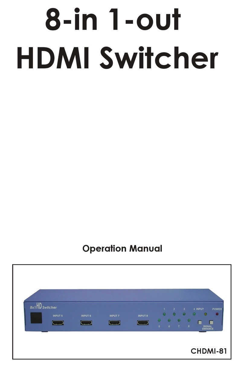
Cypress
Cypress CHDMI-81 User manual
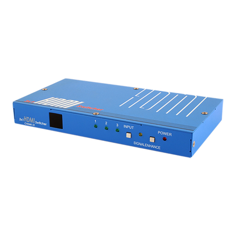
Cypress
Cypress CHDMI-31 User manual
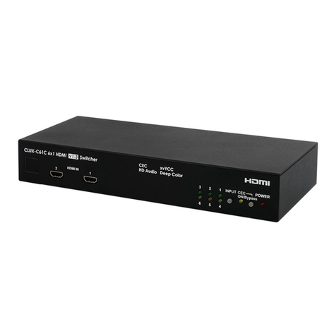
Cypress
Cypress CLUX-C61C User manual
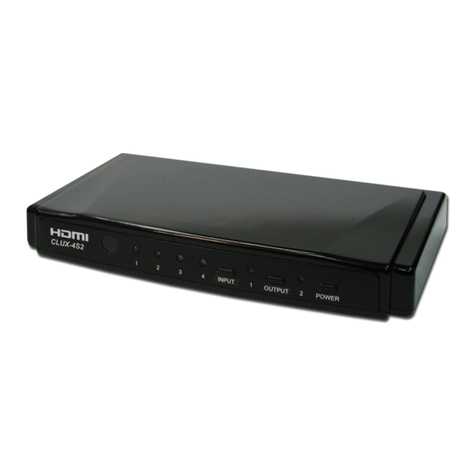
Cypress
Cypress CLUX-4S2 User manual
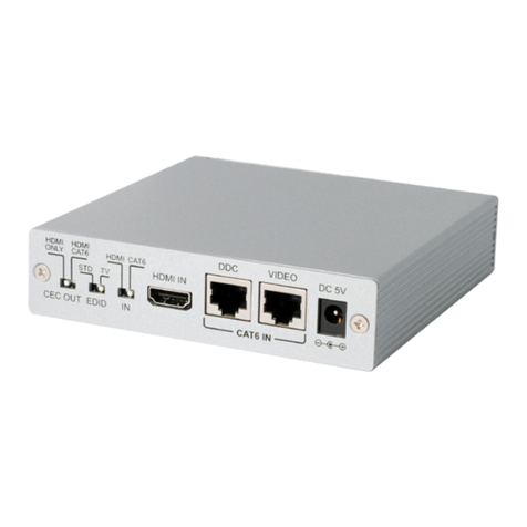
Cypress
Cypress CLUX-22HC User manual
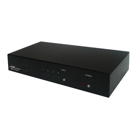
Cypress
Cypress CLUX-42S User manual
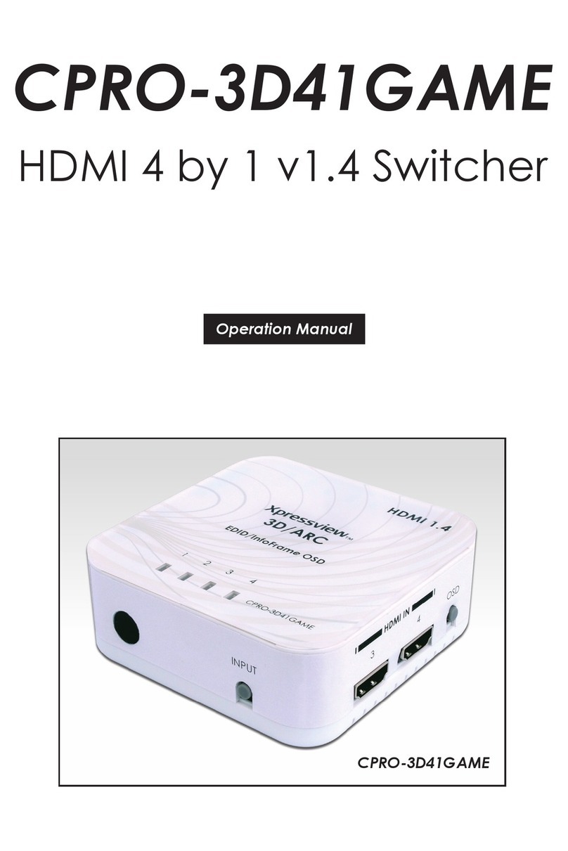
Cypress
Cypress CPRO-3D41GAME User manual
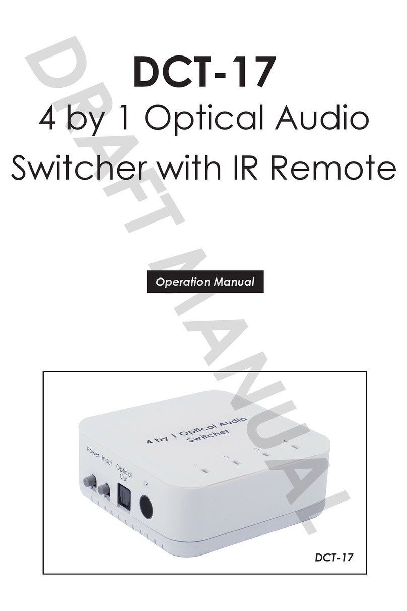
Cypress
Cypress DVT-17 User manual
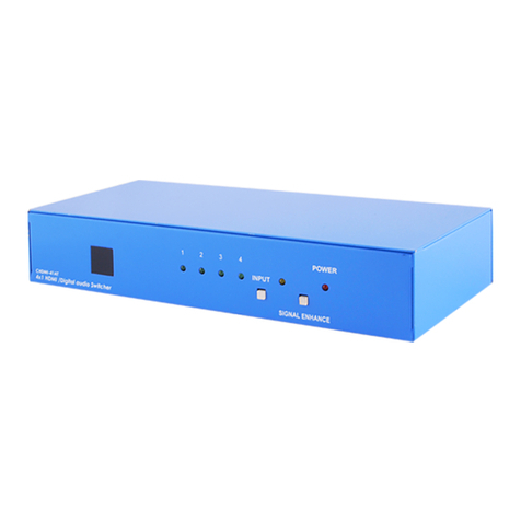
Cypress
Cypress CHDMI-41 User manual

Cypress
Cypress CHMX-42 User manual
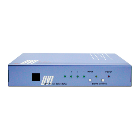
Cypress
Cypress SE-DVI-4-LC User manual
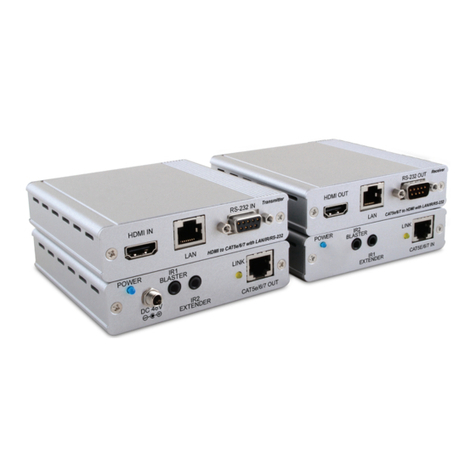
Cypress
Cypress CH-1507TX User manual
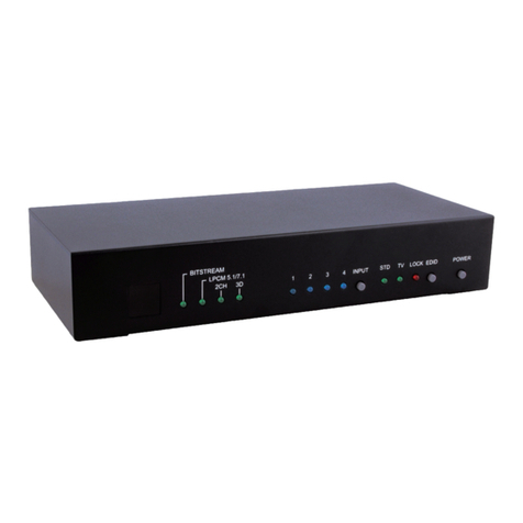
Cypress
Cypress CPRO-3D42S User manual
Cypress
Cypress CLUX-81 User manual
Cypress
Cypress CHDMI-81 User manual
Cypress
Cypress CDVI-41 User manual
Cypress
Cypress CLUX-C41 User manual
Cypress
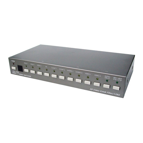
Cypress CSC-5300 User manual
Cypress
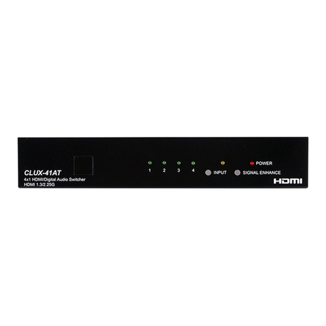
Cypress CLUX-41AT User manual
Cypress
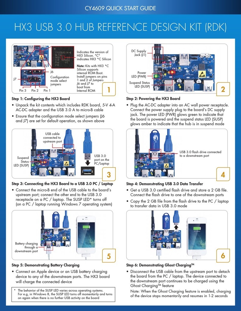
Cypress HX3 CY4609 User manual
Popular Switch manuals by other brands

SMC Networks
SMC Networks SMC6224M Technical specifications

Aeotec
Aeotec ZWA003-S operating manual

TRENDnet
TRENDnet TK-209i Quick installation guide

Planet
Planet FGSW-2022VHP user manual

Avocent
Avocent AutoView 2000 AV2000BC AV2000BC Installer/user guide

Moxa Technologies
Moxa Technologies PT-7728 Series user manual

Intos Electronic
Intos Electronic inLine 35392I operating instructions

Cisco
Cisco Catalyst 3560-X-24T Technical specifications

Asante
Asante IntraCore IC3648 Specifications

Siemens
Siemens SIRIUS 3SE7310-1AE Series Original operating instructions

Edge-Core
Edge-Core DCS520 quick start guide

RGBLE
RGBLE S00203 user manual
