DÖRR EcoPUC A User manual

MCU00002EN, V03
Translation of the original operation manual
© Dürr Systems AG 2016
Dürr Systems AG
Application Technology
Carl-Benz-Str. 34
74321 Bietigheim-Bissingen
Germany
Phone +49 7142 78-0
Internet: www.durr.com
The reproduction and distribution of this document, use and communication of its contents are not permitted
without express written approval. Offenders will be liable for damages. All rights in the event of a patent grant
or design registration are reserved.
12/2018EcoPUC A - MCU00002EN
2/40

Information about the document
This document describes the correct handling of
the product.
Read the document prior to every activity.
Prepare the document for the application.
Pass on the product only together with the com-
plete documentation.
Always follow safety instructions, handling
instructions and specifications of every kind.
Illustrations can deviate from the technical con-
struction.
Validity range of the document
This document describes the following products:
F30300001
EcoPUC A (Basic)
F30300002
EcoPUC A RA (Basic Plus)
F30300003
EcoPUC A RA BUS (Advanced)
Applicable documents
MPU00002* - Operating instructions EcoPump
HP (horizontal piston pump)
MPU00003* - Operating Instructions EcoPump
VP (vertical piston pump)
MPU00022* - Operating Instructions EcoPump
VP (vertical piston pump)
MPU00026* - Operating Instructions EcoPump
VP (vertical piston pump)
An asterisk (*) in the document number
replaces the symbol of the language variant.
Hotline and Contact
If you have queries or would like technical informa-
tion, please contact your dealer or sales partner.
12/2018 EcoPUC A - MCU00002EN 3/40

TABLE OF CONTENTS
1 Product overview...................................... 6
1.1 Overview............................................. 6
1.2 Short description................................. 6
2 Safety.......................................................... 6
2.1 Presentation of Notes.......................... 6
2.2 Intended Use....................................... 6
2.3 Safety signs......................................... 7
2.4 Staff qualification................................. 7
2.5 Personal protective equipment............ 8
3 Design and Function................................. 8
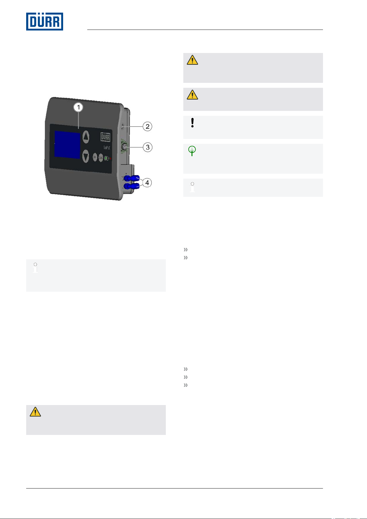
3.1 Design................................................. 8
3.2 Front.................................................... 9
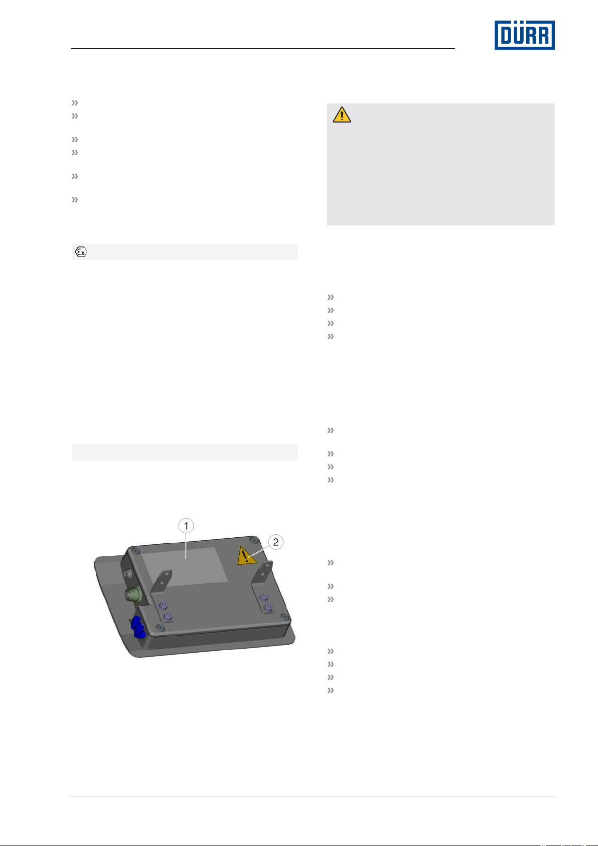
3.3 Rear..................................................... 9
3.4 Interior view......................................... 9
3.5 Profibus PA.......................................... 9
3.6 Pneumatic unit................................... 10
4 Transport, scope of supply and
storage..................................................... 10
4.1 Unpacking......................................... 10
4.2 Scope of delivery............................... 11
4.3 Handling of packaging material......... 11
4.4 Storage.............................................. 11
4.5 Transport........................................... 11
5 Assembly.................................................. 11
5.1 Safety recommendations................... 11
5.2 Assembly........................................... 11
5.2.1 Insert battery................................... 11
5.2.2 Assembling the display unit............ 12
5.3 Connecting........................................ 13
5.3.1 Grounding the display unit.............. 13
5.3.2 Connect reed switch....................... 13
5.3.3 Connecting the power supply......... 14
5.3.4 Connect compressed air supply..... 14
6 Visualizer.................................................. 15
6.1 Controls and displays........................ 15
6.2 Menus................................................ 16
6.2.1 Overview........................................ 16
6.2.2 Main menu...................................... 17
6.2.3 Actual parameter............................ 17
6.2.4 Set parameter................................. 17
6.2.5 Maintenance................................... 20
7 Commissioning....................................... 21
7.1 Safety Instructions............................. 21
7.2 General notes.................................... 21
7.3 Commissioning.................................. 21
7.3.1 Setting operating parameters ........ 21
8 Operation................................................. 22
8.1 Safety recommendations................... 22
8.2 General notes.................................... 22
8.3 Switching on...................................... 22
8.4 Switching off...................................... 22
8.5 Voltage check.................................... 22
8.6 Bleed pump....................................... 23
9 Cleaning................................................... 23
9.1 Safety recommendations .................. 23
9.2 Cleaning............................................ 24
10 Maintenance............................................. 24
10.1 Safety notes.................................... 24
10.2 Maintenance schedule.................... 24
11 Faults........................................................ 24
12 Disassembly and Disposal..................... 25
12.1 Safety recommendations................. 25
12.2 Disassembly.................................... 25
12.2.1 Disconnect compressed air
supply........................................... 25
12.2.2 Disassembling reed switch........... 25
12.2.3 Disassembling Profibus PA.......... 26
12.2.4 Assemble display unit................... 26
12.2.5 Remove battery............................ 27
12.3 Disposal .......................................... 28
13 Technical data.......................................... 28
13.1 Dimensions and weight................... 28
13.2 Connections.................................... 28
13.3 Operating conditions....................... 28
13.4 Operating values............................. 29
13.5 Compressed air quality.................... 29
13.6 Type plate........................................ 29
13.7 Operating and auxiliary materials.... 29
14 Replacement parts, tools and accesso-
ries............................................................ 29
14.1 Replacement parts.......................... 29
14.2 Tools................................................ 29
14.3 Accessories..................................... 30
14.4 Order............................................... 30
15 Index......................................................... 31
Appendix.................................................. 34
A Profibus data exchange....................... 35
B Profibus process data.......................... 36
C Profibus standard parameters............. 38
12/2018EcoPUC A - MCU00002EN4/40

1 Product overview
1.1 Overview
Fig. 1: At a glance
1 Operator interface
2 Connection for proximity switch with reed switch
3 Profibus-PA connection
4 Control air connection
– Item 3 is only valid for the variant
F30300003.
– Item 4 is only valid for the variants
F30300002 and F30300003.
1.2 Short description
The EcoPUC A (in the following “display unit”) is a
display unit for pneumatic pumps in industrial paint
systems.
Depending on the version, the display unit has a
proximity switch with reed switch, a control valve
and a Profibus PA connection Ä 3.1 “Design”.
2 Safety
2.1 Presentation of Notes
The following notes can appear in this instructions
manual.
DANGER!
High risk situation that can lead to serious inju-
ries or death.
WARNING!
Medium risk situation that can lead to serious
injuries or death.
CAUTION!
Low risk situations that can lead to minor injuries.
NOTICE!
Situations that can lead to material damage.
ENVIRONMENT!
Situations that can lead to environmental
damage.
Contains additional information and recom-
mendations.
2.2 Intended Use
Use
The display unit is designed for use in industrial
paint systems. The display unit can be used for
monitoring the following products:
EcoPump HP
EcoPump VP
The display unit is used for registering the strokes
and double strokes of a piston pump for delivering
flammable, fluid coating materials that are solvent-
or water-based.
The display unit may be used in explosive areas of
Ex zones 1 and 2.
Use the display unit only within the approved tech-
nical data Ä 13 “Technical data”.
Only use the display unit within the approved con-
nection parameters for Profibus PA (only valid for
F30300003) Ä 13.2 “Connections”.
The display unit has been designed for use with
EcoPump HP and EcoPump VP. Dürr Systems
recommends using approved components only:
Proximity switch with reed switch
Current limitation for Profibus PA
Battery (for type, see Ä 13.6 “Type plate”)
The coating material complies with explosion
group IIB. The coating material must not chemi-
cally react with aluminum.
Misuse
Wrong use of the display unit presents a risk of
injury:
Product overview
12/2018EcoPUC A - MCU00002EN6/40

Examples of wrong use are:
Use in explosive areas Ex zone 0
Setting up of processes generating strong vol-
tages in close proximity of the display unit
Operation without grounding of the housing
Modification of original parts and genuine spare
parts
Operation by unqualified personnel Ä 2.4 “Staff
qualification”
Use of components without approval by
Dürr Systems
Ex labeling
II 2G Ex ib IIB T4
II - Device group II: all areas except mining
2G - Device category 2 for gaseous ex-atmos-
phere
Ex - Device conforms to an ignition protection
category.
ib - Ignition protection category: Fail-safe
Device is suitable for Ex zones 1 and 2.
IIB - Explosion group
T4 - Temperature class
Number of the examination certificate of EU
type-approval testing
TPS 16 ATEX 41626 007 X
2.3 Safety signs
The security marking is on the rear side of the
housing.
Fig. 2: Safety Signs
1 Warning notice
2 Warning sign
2.4 Staff qualification
WARNING!
Inadequate qualification
Wrong estimation of dangers can cause serious
injury or death.
– Only sufficiently qualified persons may exe-
cute all work.
– Some work requires additional qualification.
Additional qualifications of specialized per-
sonnel are marked with a “+”.
This document is intended for qualified personnel
in the industry.
Cleaning staff
The cleaning staff receives regular instructions
from the operator about the following contents:
Using the product
Handling cleaning tools
Handling cleaning agents
Technical Measures for occupational safety and
health
Electrician
Electricians assemble, install, service and repair
electrical systems in a professional manner.
Furthermore, electrical engineers have the fol-
lowing knowledge:
Guidelines, Standards and Rules of Engi-
neering
Local conditions
Electrical Systems and Their Loading Limits
Technical Measures for occupational safety and
health
Mechanic
The mechanic is trained specifically for the field of
work in which he works.
Furthermore, he has the following knowledge:
Guidelines, Standards and Rules of Engi-
neering
Local conditions
Technical Measures for occupational safety and
health
The mechanic is responsible for the following activ-
ities on equipment and components:
Assembly
Waiting
Maintenance
Disassembly
Operator
The operator is trained specifically for the field of
work in which he works.
Safety
12/2018 EcoPUC A - MCU00002EN 7/40

Furthermore, the operator possesses the following
knowledge:
Technical Measures for occupational safety and
health
The operator is responsible for the following work:
Operate and monitor the system/ product.
Introduce measures in the event of faults.
Clean system/ product.
System operator
The system operator is trained specifically for the
field of work in which he works.
The system operator has knowledge in the fol-
lowing specialized areas:
System-specific process engineering
Knowledge of nominal process values
Technical Measures for occupational safety and
health
The system operator is responsible for the fol-
lowing tasks on equipment and components:
Operate and monitor the system.
Introduce measures in the event of faults.
Clean the system.
+ additional qualification explosion protection
In addition to the knowledge of the various spe-
cialist fields, the mechanic has knowledge of regu-
lations and safety measures when working in
potentially explosive areas.
Dürr Systems offers special product training for
Ä “Hotline and Contact”.
2.5 Personal protective equipment
When working in explosive areas, the protective
clothing, including gloves, must meet the require-
ments of DIN EN 1149-5. Footwear must meet the
requirements of EN ISO 20344 and EN IEC
61340-4-3. The volume resistivity must not exceed
100MΩ.
Wear the specified personal protective equipment
when working. Provide the following personal pro-
tective equipment:
Anti-Static Safety Boots
Protect feet from crushing, falling items
and slipping on slippery ground.
Moreover, anti-static safety boots reduce
electrostatic charge by discharging the
electrostatic charges. Safety boots must
comply with the requirements of
EN 61340-5-1. The measured volume
resistivity must not exceed 100MΩ.
Protective workwear
Tight fitting workwear with low tear
strength, tight sleeves and no hanging
parts.
3 Design and Function
3.1 Design
The display unit is available in three versions:
Description and mate-
rial number
Connections Power supply Operations/displays
EcoPUC A
F30300001
Proximity switch with reed
switch
Battery Flow rate
Wear monitoring
EcoPUC A RA
F30300002
Proximity switch with reed
switch
Control air
Battery Flow rate
Wear monitoring
EcoPUC A RA BUS
F30300003
Proximity switch with reed
switch
Control air
Profibus PA
Battery (only in the
case of uninterrupted
bus connection)
Profibus PA
Flow rate
Wear monitoring
Design and Function
12/2018EcoPUC A - MCU00002EN8/40

3.2 Front
Fig. 3: Front
1 Display
2 UP button
3 DOWN button
4 OK button
5 Escape button
6 Battery indicator
7 Status LED
3.3 Rear
Fig. 4: Rear
1 Screws
2 Fastening angle
3 Seal
4 Control air inlet (F30300002 and F30300003)
5 Control air outlet (F30300002 and F30300003)
6 Profibus-PA connection (F30300003)
7 Connection for proximity switch with reed switch
3.4 Interior view
Fig. 5: Interior view
1 Screws
2 Membrane keypad connection
3 Battery
4 Seal
5 Valve seal
6 Control valve (F30300002 and F30300003)
7 Profibus PA connection (F30300003)
8 Connection for proximity switch with reed switch
3.5 Profibus PA
Only valid for the variant F30300003
The bus parameters valid for all connected devices
are set on the master.
Standard settings of the bus parameters
Ä 13.4 “Operating values”
The device profile of the display unit is defined in a
device master data file (GSD). The device profile
must be integrated in the master. This provides the
master with general device information e.g. the
data format expected by the display unit.
The display unit is a DPv0 slave and supports
DPv0 specifications.
Data exchange
For description of the Profibus data exchange,
refer to appendix Ä “ Profibus data exchange”.
Design and Function
12/2018 EcoPUC A - MCU00002EN 9/40

3.6 Pneumatic unit
Fig. 6: Pneumatic unit
Fig. 7: Schematic representation
The pneumatic unit is installed between display
unit and pump. The pneumatic unit has a 5/2
working valve (1). The working valve (1) ensures
that the pump is supplied with sufficient com-
pressed air. The working valve (1) is required as
the 3/2 control valve (2) of the display unit is
unable to supply the pump with sufficient com-
pressed air.
The pneumatic unit is available as acces-
sory Ä 14.3 “Accessories”.
Schematic representation, see also
Ä “Wiring diagram”
4 Transport, scope of supply and
storage
4.1 Unpacking
Personnel:
Operator
Protective equipment:
Protective workwear
Anti-Static Safety Boots
1. Check the display unit packaging for damage.
ðImmediately notify the customer service of
any damage Ä “Hotline and Contact”.
2. DANGER!
Danger of explosion from static charges
on plastic film and foils
Plastic wrapping of the display unit:
Remove before entering the explosive area.
Remove prior to commissioning.
ENVIRONMENT!
Environmental damage due to wrong disposal
3. Keep packaging material for storage or trans-
port.
4. Check unpacked display unit for damage.
5. Transport display unit to the assembly location.
Transport, scope of supply and storage
12/2018EcoPUC A - MCU00002EN10/40

4.2 Scope of delivery
The scope of supply includes the following compo-
nents:
Display unit
Battery
Proximity switch with reed switch
Fastening bracket for EcoPump VP or
EcoPump HP
1. Inspect delivery on receipt for completeness
and integrity.
2. Report defects immediately Ä “Hotline and
Contact”.
4.3 Handling of packaging material
ENVIRONMENT!
Incorrect disposal
Incorrectly disposed packaging material can
damage environment.
– Dispose of material no longer required in an
environment-friendly manner.
– Observe local disposal specifications.
4.4 Storage
Requirements for the warehouse:
Do not store outdoors.
Store in a dry and dust-free place.
Do not expose to aggressive media.
Protect from solar radiation.
Avoid mechanical vibrations.
Temperature: -30° C to 65°C
Relative humidity: 35% to 90%
Remove the battery from the housing before
storing the display unit Ä 12.2 “Disas-
sembly”.
4.5 Transport
Personnel:
Mechanic
Protective equipment:
Protective workwear
Anti-Static Safety Boots
Requirements:
Ensure that all the hoses and lines have been
removed Ä 12.2 “Disassembly”.
Display unit is disassembled Ä 12.2 “Disas-
sembly”.
1. Use the original packing for transporting.
If the original packing is no longer available, the
packing used must meet the following require-
ments:
Comprehensive protection from vibrations
Protection from dirt
Protection from moisture
5 Assembly
5.1 Safety recommendations
WARNING!
Explosion danger due to electrostatic charge
The housing can become electrostatically
charged. Electrostatic discharge can cause
sparks. In an explosive atmosphere, these
sparks can prove to be the source of ignition for
an explosion. Serious injury and death could be
the consequence.
– Bolt the housing without insulating layers with
a grounded metal component.
– Do not use plastic underlays (e.g. rubber
buffer) for assembly.
– Assembly on insulating components is not
allowed.
– Wear specified protective equipment.
WARNING!
Explosion danger due to work at the display
unit
Working on the display unit in an explosive
atmosphere can cause fire or an explosion.
Serious injury and death could be the conse-
quence.
– Conduct work on the display unit only in the
workshop, outside of Ex zones.
5.2 Assembly
5.2.1 Insert battery
WARNING!
Danger of explosion due to battery replace-
ment
Replacing a battery in explosive atmosphere can
cause fire or an explosion. Serious injuries and
death can be the consequence.
– Only replace battery outside the Ex zone.
Assembly
12/2018 EcoPUC A - MCU00002EN 11/40

WARNING!
Explosion danger due to contamination
If the display unit is not properly sealed, contami-
nants can reach interior of the device. Dirt inside
the device (e.g. on the board) can trigger short-
circuits. It can cause fire or an explosion. Serious
injury and death could be the consequence.
– Do not use leaking display unit in explosive
areas.
– Replace damaged seals.
– If the interior of the device is contaminated,
have the display unit cleaned only by
Dürr Systems Ä “Hotline and Contact”.
WARNING!
Danger of explosion due to damaged board
Changing the battery can damage the board.
Damages to the board can cause short circuit. It
can cause fire or an explosion. Serious injuries
and death can be the consequence.
– Do not touch the board when changing the
battery.
– ESD protective measures are required, in
order not to damage the board.
Personnel:
Mechanic
+ additional qualification explosion protection
Requirements:
Suitable aids (e.g. tools) are available.
Fig. 8: Rear of device
1. Unscrew screws (1) on the housing lid (2).
2. Remove housing lid (2) and seal (3).
Fig. 9: Insert battery
3. For specifications of the battery, refer to
Ä 14.1 “Replacement parts”.
Fit battery (5) at an angle to the poles (4).
4. Push battery down into the battery housing (6).
5. Check seal for damage before assembly. If seal
is damaged, use a new seal.
6. Place seal (3) and housing lid (2) onto the
housing.
7. Fasten screws (1).
5.2.2 Assembling the display unit
CAUTION!
Falling down of the display unit
If the display unit is not attached to the pump, the
display unit may fall down. Simply leaning the
display unit at the pump is not permitted. This
may cause injuries.
– Attach display unit to the pump by using fas-
tening brackets.
– Wear specified protective equipment.
Personnel:
Mechanic
+ additional qualification explosion protection
Requirements:
Suitable aids (e.g. tools) are available.
Assembly
12/2018EcoPUC A - MCU00002EN12/40

Fig. 10: Assemble fastening bracket
1. Assemble fastening bracket (2) to the display
unit by using screws (3).
The bores (1) on the fastening bracket are
intended for attaching the display unit onto
EcoPump HP or EcoPump VP.
2. Attach display unit to the pump.
For more information regarding the
assembly, see the relevant operating
instructions of EcoPump HP and
EcoPump VP Ä “Applicable documents”.
5.3 Connecting
5.3.1 Grounding the display unit
Personnel:
Mechanic
+ additional qualification explosion protection
Requirements:
Suitable aids (e.g. tools) are available.
1. Ground the display unit:
Via the connection to the pump
Via a separate grounding line if no pump is
used.
Checking grounding
2. Measure and document volume resistivity.
5.3.2 Connect reed switch
Personnel:
Mechanic
+ additional qualification explosion protection
Requirements:
Suitable aids (e.g. tools) are available.
Fig. 11: Connect reed switch
WARNING!
Danger of explosion due to unsuitable
replacement parts
If you use replacement parts that do not comply
with the specifications of the ATEX guidelines,
the replacement parts can cause explosions in
an explosive atmosphere. Serious injury and
death could be the consequence.
– Use only proximity switch with reed switch
from Dürr Systems.
1. Insert proximity switch with reed switch (2) in
the bushing (1).
For how to restore the connection to
EcoPump HP or EcoPump VP, see associ-
ated operating instructions Ä “Applicable
documents”.
Assembly
12/2018 EcoPUC A - MCU00002EN 13/40

5.3.3 Connecting the power supply
Personnel:
Electrician
Requirements:
Suitable aids (e.g. tools) are available.
Power supply through battery
1. Insert battery Ä 5.2.1 “Insert battery”.
ðPower supply is connected.
Power supply through Profibus PA
Only valid for the variant F30300003
Fig. 12: Connect Profibus PA plug
2. Insert Profibus PA plug into the bushing (1).
Observe connection parameters when selecting
the Profibus PA supply device Ä 13.2 “Connec-
tions”.
ðPower supply is connected.
5.3.4 Connect compressed air supply
Personnel:
Mechanic
Requirements:
Suitable aids (e.g. tools) are available.
Fig. 13: Pneumatic unit
1. Connect pneumatic unit to the pump.
For further information on connecting to
the pump, see the EcoPump operating
instructions under Ä “Applicable docu-
ments”.
2. Connect hose of the control air inlet (1) to the
pneumatic unit.
3. Connect hose of the control air outlet (2) to the
pneumatic unit.
Fig. 14: Display unit
4. Connect hose of the control air outlet (3) to the
display unit.
5. Connect hose of the control air inlet (4) to the
display unit.
ðCompressed air supply is connected.
For wiring diagram of the pneumatic unit,
see Ä “Wiring diagram”
Assembly
12/2018EcoPUC A - MCU00002EN14/40

6 Visualizer
6.1 Controls and displays
Controls
Fig. 15: Controls
Item Key Function Example
1 UP Increase
High
Increase value.
Enter previous menu.
2 DOWN Decrease
Below
Decrease value.
Enter next menu.
3 OK Confirm Select menu.
Confirm value.
Acknowledge error message.
4 ESC Return Cancel entry.
Change to the next upper menu level.
Visualizer
12/2018 EcoPUC A - MCU00002EN 15/40

Controls
Fig. 16: Controls
1 Display
2 Battery
3 Error LED
LED Color Activity Operating status
Battery - None Power supply through battery
Green Lights up continuously Power supply through Profibus PA (only
valid for F30300003)
Lights up for 2 seconds Battery level low
Quickly flashes 5 times Battery level very low:
Change battery.
Error - None Display unit switched off or not ready for
operation
Red Flashes continuously Battery voltage too low, display unit cannot
start.
Flares up briefly every 4 sec-
onds
Display unit ready for operation, no errors
present.
Flares up briefly every
second
At least one error is present.
6.2 Menus
6.2.1 Overview
The display unit has the following menus:
Main menu (system status)
Actual parameter
Set parameter
Maintenance
Visualizer
12/2018EcoPUC A - MCU00002EN16/40

6.2.2 Main menu
Fig. 17: Main menu (system status)
The number of the current error and warnings is
displayed in the main menu.
1. Acknowledge errors and warnings by pressing
[OK].
ðError LED turns out.
Errors and warning that were not saved can be
recognized from:
Flashing behavior of the error LED
Message on the display
Error
The following errors are displayed:
Dry run
Communication (only valid for F30300003)
Reed switch
Control valve
Communication errors are only displayed
after a Profibus PA connection (only valid for
F30300003).
– Connect Profibus PA.
Ä 5.3.3 “Connecting the power supply”
Warnings
The following warnings are displayed:
Maintenance due
Battery low
Disconnection from power supply deletes
the internal memory for errors and warnings.
– Disconnect from power supply.
Ä 12.2.5 “Remove battery”
6.2.3 Actual parameter
6.2.3.1 Overview
Fig. 18: Actual parameters menu
The following settings and displays are present:
Displacement volume in l/min
Displacement volume in gal/min
Double stroke frequency in DH/min
Number of strokes in total
Number of strokes since last maintenance
Date and clock time
6.2.3.2 Double stroke counting and displacement
volume
The reed switch records double strokes. The reed
switch emits a pulse per executed double stroke.
The displacement volume in l/min and gal/min is
calculated based on the double stroke frequency,
using the “double stroke volume” parameter. The
“Double stroke volume” is set in the “Set param-
eter” menu.
6.2.4 Set parameter
6.2.4.1 Overview
Fig. 19: Set parameters menu
Visualizer
12/2018 EcoPUC A - MCU00002EN 17/40

The following settings and displays are present:
Double stroke volume
Dry run protection threshold value (only valid for
F30300002 and F30300003)
Activate/ deactivate dry run protection (only
valid for F30300002 and F30300003
Maintenance interval
Volumetric measurement double stroke rate
(only valid for F30300002 and F30300003)
Language
Battery warning threshold value
Display disabling time
Switching the display illumination on/off
Profibus slave address (only valid for
F30300003)
Access mode remote controlled/local/both (only
valid for F30300003)
Date and clock time
6.2.4.2 Parameter input
Personnel:
System operator
Parameter input by using the menu
1. In the main menu, select the required parame-
ters by using [UP] or [DOWN].
2. Confirm with [OK].
ðSelected parameter is blinking.
In case of numerals, the individual decimal
places are changed successively. The rele-
vant place is blinking.
3. Change parameter by using [UP] or [DOWN].
4. Confirm selection with [OK].
ðThe parameter has been changed.
The entry can be aborted by using
[ESC].
Parameter input by using Profibus PA
Only valid for the variant F30300003
For further information, refer to Ä “Profibus
process data”
Parameters are only incorporated in the following
cases:
Output parameter has changed in comparison
with the previous DataExchange notification.
Output parameters do not all have the value
zero.
Access mode “both” or “remote controlled” is
set.
6.2.4.3 Dry run protection
Only valid for the variants F30300002 and
F30300003
The display unit calculates a double stroke fre-
quency (DH/min). The double stroke frequency is
compared to a stored threshold value. If the
threshold value is crossed, the error LED flashes.
Personnel:
Operator
1. Select “Dry run protection” in the Set parame-
ters menu.
2. Confirm with [OK].
ðThe dry run protection function is active.
In addition, the control valve of the display
unit is activated.
With pneumatic unit: The control valve
interrupts the air supply of the pump, in
order to protect it from a dry run.
Without pneumatic unit: The control valve
controls the working valve. The working
valve interrupts the air supply of the pump,
in order to protect it from a dry run.
3. Acknowledge error LED by pressing [OK].
ðThe control valve is again deactivated.
The control valve has a high power con-
sumption. Promptly acknowledge and
remove dry run error, to preserve battery
service life.
Remove dry run error:
Check material supply to the pump.
6.2.4.4 Languages
Personnel:
Operator
1. Select “Language” in the Set Parameter menu.
2. Confirm with [OK].
ðThe selection flashes.
3. Set the desired language using [UP] or
[DOWN].
4. Confirm with [OK].
ðThe language is set.
Visualizer
12/2018EcoPUC A - MCU00002EN18/40

6.2.4.5 Display illumination
Personnel:
Operator
Switching off the display illumination reduces the
power consumption.
1. Select “Display illumination” in the Set param-
eter menu.
2. Confirm with [OK].
ðThe selection flashes.
3. Select the desired illumination setting using
[UP] or [DOWN].
Automatic: If no key is pressed, the illumina-
tion switches off after the time set in the
“Display deactivation time” menu.
Always off: Illumination is always switched
off.
If you press [ESC] for 5 seconds, the display
illumination is switched off manually.
Pressing any key will switch on the display
illumination again. Pressing the key will not
trigger any further action.
6.2.4.6 Access mode
Only valid for the variant F30300003
Personnel:
Operator
1. Select “Access mode” in the Set parameters
menu.
2. Enable selection with [OK].
ðThe selection flashes.
3. Select the desired access mode using [UP] or
[DOWN].
Locally: Edit parameters on the display unit.
Remote controlled: Edit parameters through
Profibus PA.
Both: Edit parameters on the display unit or
through Profibus PA.
4. Confirm with [OK].
The “Access mode” parameter can
always be edited through the display unit
or via the Profibus PA.
The “Implement volumetric measure-
ment” and “Carry out maintenance” func-
tions are only possible locally on the dis-
play unit.
6.2.4.7 Setting Date and Clock Time
Personnel:
Operator
1. Select “Date and time” in the Set parameters
menu.
2. Press [OK].
ðThe selection flashes.
3. Change the numerical value using [UP] or
[DOWN].
4. Confirm the changed numerical value using
[OK].
If the power supply was interrupted, set date
and clock time again.
6.2.4.8 Profibus slave address.
Only valid for the variant F30300003
The slave address of the display unit is by default
set to 0008.
Change slave address Ä 6.2.4.2 “Parameter
input”.
6.2.4.9 Energy saving mode
Only valid for the variants F30300001 and
F30300002
If the following conditions are fulfilled, the energy
saving mode is enabled automatically:
Control valve is not active.
Volumetric measurement process is not active.
Maintenance process is not active.
No keys have been pressed.
Activating energy saving mode manually:
Press [ESC] key for 5 seconds.
The energy saving mode is deactivated under the
following conditions:
Keep the [ESC] key pressed for 5 seconds.
Warnings or error messages have appeared.
In the energy saving mode, the monitoring function
continues to be active.
Visualizer
12/2018 EcoPUC A - MCU00002EN 19/40

6.2.5 Maintenance
6.2.5.1 Overview
Fig. 20: Maintenance menu
The following values can displayed and selected in
the “Maintenance” menu:
Device version
Implement volumetric measurement
Carry out maintenance.
6.2.5.2 Device version
Fig. 21: Device version (example)
1 Product name
2 Type (Basic, Basic Plus, Advanced)
3 Serial number
4 Software version
6.2.5.3 Implement volumetric measurement
Only valid for the variants F30300002 and
F30300003
Personnel:
Operator
1. Select “Carry out volumetric measurement” in
the Maintenance menu.
2. Confirm with [OK].
3. Set container below the volumetric measure-
ment opening of the pump.
4. Click [OK] to confirm “Start volumetric measure-
ment?”
ðIf the pump is at a standstill, the volumetric
measurement process starts. The double
strokes are displayed.
5. After the volumetric measurement:
Check volumetric measurement quantity.
The volumetric measurement quantity
depends on the pump version and the
number of double strokes.
If the volumetric measurement quantity is
not correct, check the pump for wear
Ä “Applicable documents”.
If an error occurs during the volumetric measure-
ment process, the process is aborted.
Abort the process manually, using the [ESC]
key.
If the battery level is very low, the volumetric
measurement process will not start.
6.2.5.4 Carry out maintenance
Personnel:
Operator
+ additional qualification explosion protection
Requirements:
Compressed air supply is switched off and
secured against being switched on again.
Depressurize the system.
Maximum value of the double stroke in the
“Maintenance interval” menu is reached.
Display of the “Maintenance due” warning on
the display
1. Confirm “Carry out maintenance” in the Mainte-
nance menu, by pressing [OK].
2. Click [OK] to confirm “Start maintenance?”
ðMaintenance is enabled.
3. Perform maintenance work.
4. Press [OK] when maintenance is over.
ðThe message “Maintenance concluded” is
displayed.
The warning “Maintenance due” and the
counter in the “Maintenance interval” menu
are reset.
Visualizer
12/2018EcoPUC A - MCU00002EN20/40
Table of contents
Other DÖRR Industrial Equipment manuals
Popular Industrial Equipment manuals by other brands

MICROMATIC
MICROMATIC PREMIUMPLUS quick start guide

Midwest
Midwest V4 Installation & operation manual

OEM Tools
OEM Tools 24950 Operating instructions and parts manual

MICROMATIC
MICROMATIC PREMIUMPLUS100 instruction manual

TAN Bead
TAN Bead Maelstrom 4810 user manual

woodmizer
woodmizer CBT-430 Safety, Operation, Maintenance & Parts Manual