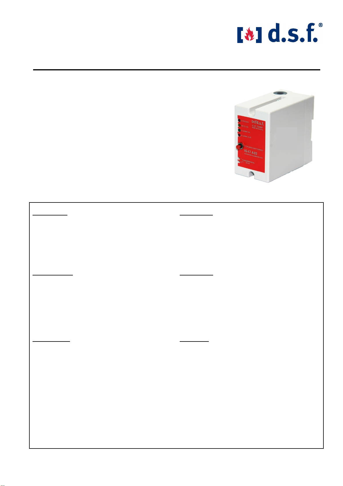
d.s.f. GmbH IG47 A02 Seite / Page 7 Stand 09/2013
Anschluss der Ionisationselektrode:
Bei Verwendung als Zünd- und
Überwachungselektrode
Zur Vermeidung von hochfrequenten Zündtransformator-
Störungen ist unbedingt ein entstörter
Zündkerzenstecker zu verwenden oder ein 1 kW-
Entstör-Widerstand in das Anschlusskabel unmittelbar
vor dem Zündbrenner einzubauen.
Die Masse Verbindungsleitung zwischen dem
Steuergerät und der Brennermasse sollte einen
Querschnitt von mindestens 6 mm
2
haben.
Verwenden Sie Kabel mit sehr hohem Isolations-
widerstand.
Kabelempfehlung:
Isoliertes 1,5 mm
2
Kabel, (z.B. d.s.f. Typ 0373) für die
Verbindung von lonisationselektrode zum lonisations-
Flammenwächter. Es darf keine Abschirmung verwendet
werden. Der Masseausgang des IG47 A02 muss mit
einer separaten Leitung mit der Brennermasse
verbunden werden. Sternförmige Masseverlegung.
Die lonisationselektrode ist an Klemme 12 und die Masse
an Klemme 11 des Flammenwächters anzuschließen.
Die Verbindungsleitung ist getrennt von anderen
spannungsführenden Leitungen, möglichst auf
separater Trasse, zu verlegen.
Sicherheitshinweis:
Bei eingeschalteter Versorgungsspannung des
Flammenwächters liegt eine Wechselspannung von max.
310 VAC an der Ionisations-Elektrode an. Die
Sicherheitsvorschriften und VDE-Bestimmungen sind
einzuhalten. Vor Ausbau des Brenners muss das Gerät
spannungsfrei geschaltet werden.
Während des Einbaus und Anschlusses ist darauf zu
achten, dass keine gefährliche Spannung anliegt.
Zum Umschalten des DIP-Schalters S1, Gerät von der
Netzspannung trennen.
Das Gerät darf keiner Feuchtigkeit ausgesetzt werden.
Störungen, Ursache und Beseitigung
Störungen, die durch starke EMV-Einstrahlungen
auftreten, können bei Aufleuchten der LED “Störung”
durch Drücken des Quittiertasters “Störungs-Quittierung”
beseitigt werden. Sollte das Gerät einen bleibenden
Fehler haben, muss es zur Reparatur an den Hersteller
oder einer autorisierten Vertretung zugeschickt werden.
Electrical connection of the flame rod:
When used as ignition and monitoring electrode
To avoid high-frequent electromagnetic noises use
interference suppressed spark plug or install a 1 kW
interference resistor in the connecting cable
immediately prior to the pilot burner.
The ground connection cable between the control unit
and the ionization electrode should have a minimum
cross section of 6 mm².
Use only cable with high insulation resistance
Cable Recommendation:
Iinsulated 1,5 mm² cable, (for example d.s.f. type
0373) to connect the electrode with the Ionization
Flame Safeguard Control. There shall be no isolation
are used. The ground of the IG47 A02 has to be
connected with a separate wiring to the burner
ground. Star-shaped ground lying.
Connect the electrode to terminal 12 and the ground
on terminal 11 at the ionization flame safeguard.
The connection cable must be routed separately
from other voltage cables, preferably on a
separate track.
Safety Instructions:
On connected power supply to Safeguard Control, an
AC Voltage of max. 310 VAC is applied. Please take
the safety rules and VDE-instructions into
consideration. Before dismounting the burner, the
instrument must be free of tension.
During the installation and connection, make sure that
no hazardous voltage is present.
For change-over the DIP-switch S1, disconnect
instrument from power supply.
Don`t expose the instrument to humidity.
Interferences, reasons and removing
Interferences appeared by strong EMV-insulations can
on lighting up of the LED “Störung”. This can be
resetted by pressing the push-button
“Störungsquittierung”.
Should the instrument have a remaining error, it has to
send for repair to the manufacturer or an authorized
represent.