d.s.f. IG49 Series User manual

Internationales Know-How in der Flammenüberwachung
International know-how in flame monitoring
Betriebsanleitung
Operating Manual
d.s.f. GmbH IG49, REV 0 Seite / Page 1 / 18 04/2021
Die Betriebsanleitung ist vor
Montage, Inbetriebnahme und
Wartung sorgfältig zu lesen.
Die Hinweise sind zu beachten
und die Betriebsanleitung ist
für eine spätere Verwendung
aufzubewahren!
The operating instructions must be read
carefully before installation,
commissioning and maintenance. The
instructions must be observed and the
operating instructions must be kept for
later use!
IG49
Serie
Series
Selbstüberwachender
Ionisations-Flammenwächter
Self-monitoring Ionization
Flame Safeguard

d.s.f. GmbH IG49, REV 0 Seite / Page 2 / 18 04/2021
Betriebsanleitung IG49 Serie
Operating Manual IG49 Series
Dokumentname
Betriebsanleitung IG49 Serie
Document name
Operating Manual IG49 Series
Aktuelle Ausgabe / Current edition:
00
Erstausgabe / First edition:
06.04.2021
letzte Aktualisierung:
last revision
Die Texte und Abbildungen wurden mit größter Sorgfalt
erarbeitet. Die d.s.f. GmbH (und die Autoren) können
für eventuell verbliebene fehlerhafte oder
unvollständige Angaben und deren Folgen weder eine
juristische noch irgendeine Haftung übernehmen.
Ohne vorherige schriftliche Genehmigung der
d.s.f. GmbH darf die Dokumentation oder Teile daraus
nicht reproduziert, kopiert oder an Dritte verliehen oder
weitergegeben werden.
Die d.s.f. GmbH, als Hersteller des beschriebenen
Ionisationsflammenwächtersystems, behält sich das
Recht vor, jederzeit - auch ohne Vorankündigung - die
Ausstattung und Ausführung der Gerätemodule oder
einzelner Baugruppen zu ändern. Die tatsächliche
Verfügbarkeit ergibt sich aus dem jeweils erstellten
individuellen Angebot.
Es erfolgt keine Benachrichtigung, wenn Inhalte
geändert werden.
Abbildungen können durch die Darstellung von
kundenbasierten Sonderlösungen oder
Weiterentwicklungen abweichen, hieraus leitet sich
kein Anspruch auf die Lieferung identischer Produkte
ab.
The texts and illustrations have been compiled with
the greatest care. The d.s.f. GmbH (and the authors)
cannot assume any legal or other liability for any
remaining incorrect or incomplete information and its
consequences.
Without prior written permission of d.s.f. GmbH, the
documentation or parts of it may not be reproduced,
copied or lent or passed on to third parties.
The d.s.f. GmbH, as manufacturer of the described
ionization flame monitor system, reserves the right to
change the equipment and design of the device
modules or individual assemblies at any time - even
without prior notice. The actual availability results
from the individual offer prepared in each case.
No notification is given when content is changed.
Illustrations may differ from the illustrations due to the
depiction of customer-based special solutions or
further developments, which does not entitle the
customer to the delivery of identical products.

d.s.f. GmbH IG49, REV 0 Seite / Page 3 / 18 04/2021
Inhaltverzeichnis / Table of Contents
Inhaltverzeichnis / Table of Contents ........................................................................................................................3
Bildverzeichnis / Image directory...............................................................................................................................3
Beschreibung / Description........................................................................................................................................4
Generelle Arbeitsweise / General function ................................................................................................................4
Sicherheitshinweise und Schutzmaßnahmen / Safety instructions and precautions................................................5
Haftungsbeschränkungen / Limitations of Liability ....................................................................................................6
Übersicht der Geräte und Zubehör / Overview of Components and Accessories..................................................... 6
Funktion / Function....................................................................................................................................................7
Technische Daten / Technical Specifications............................................................................................................9
Anforderungen in einer SIL2 Umgebung und bei Versorgungsspannung bis 230VAC für die Kontakte des
Sicherheitskreises / Requirements in a SIL2 environment and up to 230VAC supply voltage for the contacts of the
safety circuit.............................................................................................................................................................10
Montage der Ionisationselektrode / Flame Rod Installation ....................................................................................14
Montage der Ionisationselektrode (weiter) / Flame Rod Installation (further on) ....................................................15
Anschluss der Ionisationselektrode / Connection of the ionization electrode .........................................................16
Kabelempfehlung und -anschluss / Cable recommendation and connection IG49-Serie.......................................16
Sicherheitshinweise / Safety instructions ................................................................................................................17
Störungen, Ursache und Beseitigung / Interference, Cause and Remedy .............................................................17
Garantie / Guarantee...............................................................................................................................................18
Haftung / Liability.....................................................................................................................................................18
Bildverzeichnis / Image directory
Minimal- und Maximalwerte der Flammendetektion / Minimum and maximum values of flame detection ...............8
Prinzipschaltbild / Schematic diagramm IG49 A03 (115 / 230 VAC) / IG49 A02 (24 VDC)....................................10
Prinzipschaltbild für IG49-Serie...............................................................................................................................11
Schematic diagramm for IG49 series ......................................................................................................................12
Gehäuseabmessungen / Housing dimensions........................................................................................................13
Positionierung Ionisationselektrode / Positioning ionization electrode....................................................................14

d.s.f. GmbH IG49, REV 0 Seite / Page 4 / 18 04/2021
Beschreibung / Description
Der Ionisationsflammenwächter IG49 ist ein selbst-
überwachender Flammenwächter, zugelassen nach
DIN EN 298 für Dauerbetrieb, für Gasbrenner
beliebiger Leistung, mit und ohne Gebläse und dient
zur Überwachung von Industrie-Brennern an Öfen in
Raffinerien und in der Petrochemie, wo ein Höchstmaß
an Sicherheit und Verfügbarkeit gefordert wird.
Der Ionisationsflammenwächter ist für 24 VDC,
115 VAC und 230 VAC für die Hutschienenmontage
erhältlich.
Anforderungen in einer SIL2 Umgebung und bei
Versorgungsspannung bis 230VAC für die Kontakte
des Sicherheitskreises sind auf Seite 10 erklärt.
The ionization flame monitor IG49 is a self-monitoring
flame monitor, approved in accordance with DIN EN
298 for continuous operation, for gas burners of any
capacity, with or without fan and is used for monitoring
industrial burners in furnaces in refineries and in the
petrochemical industry, where a maximum of safety
and availability is required.
The ionization flame detector is available for 24 VDC,
115 VAC and 230 VAC for DIN rail mounting.
Requirements in a SIL2 environment and up to
230VAC supply voltage for the contacts of the safety
circuit are explained on page 10.
Generelle Arbeitsweise / General function
Bei fachgerechtem Einbau fließt zwischen
Ionisationselektrode und der Masse des Brenners ein
Strom, sobald die Luftstrecke durch das
Vorhandensein einer Gasflamme ionisiert ist. Mit der
Ionisierung verbunden ist ein Gleichrichteffekt, der
einen Stromfluß von der Masse zur Elektrode bewirkt
(Elektronenflußrichtung).
Der Meßkreis über die ionisierte Luftstrecke wird von
der Eingangsschaltung her mit einer Wechsel-
spannung beaufschlagt, wodurch sich zwei markante
Betriebszustände ergeben, die absolut eindeutig und
zuverlässig das Vorhandensein einer Flamme bzw.
einen möglichen Fehler signalisieren:
When properly installed, a current flow between the
ionization electrode and the ground of the burner as
soon as the air gap is ionized by the presence of a gas
flame. The ionization is connected to the ionization
process by an equalizing effect, which causes a current
flow from the ground to the electrode (direction of the
electron flow).
The measuring circuit over the ionized air gap is
supplied with an AC voltage from the input circuit,
which results in two distinct operating states that
indicate absolutely unambiguously and reliably the
presence of a flame or a possible fault:
Analogsignal an
Prüfbuchse
(oder internem
Schraubkontakt)
Ursache
Status
Flammenrelais
Analog output at
test jackets
(or internal
connection)
Reason
Status
Flame Relay
4 mA
Flamme aus,
Kurzschluß
oder
Unterbrechung
abgefallen
4mA
Flame off, short-
or open circuit
de-energized
> 4,8 mA
Flamme an
angezogen
> 4,8 mA
Flame on
energized
Die fehlerhaften Zustände (Kurzschluss und
Unterbrechung im Elektroden-Stromkreis) führen
gleichermaßen zur Stromlosigkeit des Flammenrelais
und damit zur Abschaltung der Brennstoffzufuhr und
zum Erlöschen der Flamme.
The faulty states (short- or open circuit in the electrode
circuit) thus lead equally to the de-energization of the
flame relay and thus to the shutdown of the fuel supply
and causes the flame to extinguish.

d.s.f. GmbH IG49, REV 0 Seite / Page 5 / 18 04/2021
Sicherheitshinweise und Schutzmaßnahmen / Safety instructions and precautions
Sicherheit bei Bedienung und im Betrieb:
Unsachgemäßer Umgang kann zu erheblichen
Personen- und Sachschäden führen.
Arbeiten an dem Hochenergie-Zündsystem darf nur
entsprechend ausgebildetes Bedienungspersonal oder
eine Elektrofachkraft durchführen.
Bedienungspersonal ist eine Person, die für
Installation, Betrieb, Einrichten, Wartung, Reinigung,
Reparatur oder Transport von Geräten und Maschinen
zuständig ist, so dass sie Gefahren erkennen und
vermeiden kann.
Elektrofachkraft ist eine Person mit geeigneter
fachlicher Ausbildung, Kenntnissen und Erfahrung, so
dass sie Gefahren erkennen und vermeiden kann, die
von der Elektrizität ausgehen können.
Sicherheit bei Lagerung, Montage , Installation und
Wartung
Der einwandfreie und sichere Betrieb des Gerätes setzt
sachgemäßen Transport, fachgerechte Lagerung,
Aufstellung und Montage sowie eine sorgfältige
Bedienung voraus.
Es besteht Lebensgefahr bei Berührung von
spannungsführenden Komponenten, daher ist eine
regelmäßige Sichtkontrolle durch den Anwender
festzulegen. Die Sichtkontrolle beschränkt sich auf die
Unversehrtheit der angeschlossenen Kabel, der
mechanischen Anschlüsse und dem festen Sitz der
Schrauben. Eine gute Erdung ist ein wichtiger
Bestandteil der Funktionsweise. Eine Überprüfung zur
Einhaltung der zulässigen Umgebungstemperaturen ist
erforderlich.
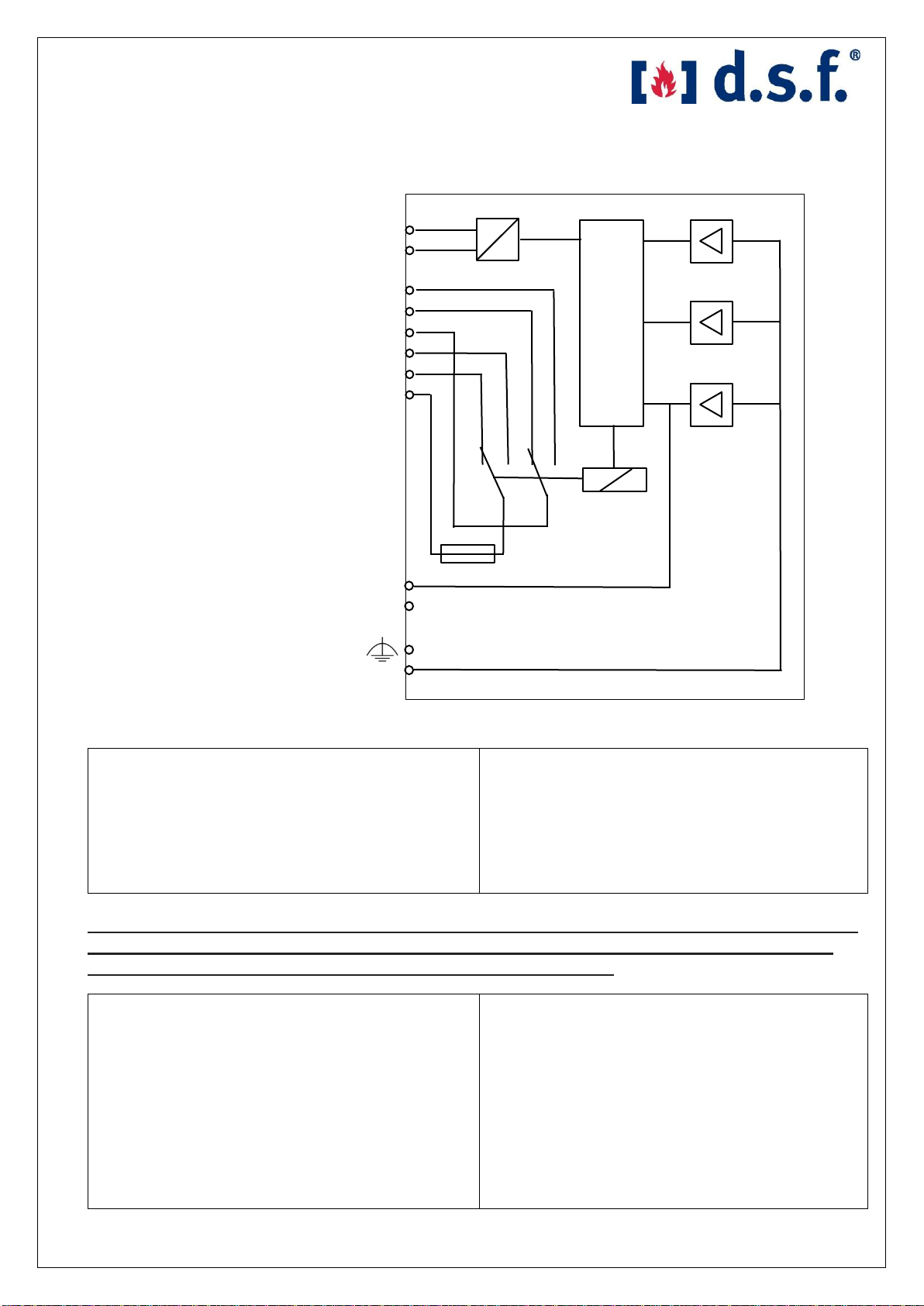
Der Ionisationsflammenwächter darf nur mit
geschlossenem Deckel, im eingebauten Zustand und
mit einem im Feuerraum befindlichen Ionisationsstab
betrieben werden.
In dem Ionisationsflammenwächter wird eine
Spannung von max. 300VAC erzeugt, daher muss bei
der Feststellung einer Beschädigung das
Flammenüberwachungssystems außer Betrieb
genommen und zur Reparatur eingesendet werden.
Vor allen Arbeiten ist die Spannungsversorgung
abzuschalten, gegen Wiedereinschalten zu sichern
und die Spannungsfreiheit zu überprüfen.
Es kann bei einem notwendigen Ausbau des
Ionisationsstabes Verbrennungsgefahr bestehen. Die
Verwendung von Schutzhandschuhen und
Arbeitsschutzkleidung ist erforderlich.
Safety in handling and operation:
Improper handling can lead to considerable personal
injury and material damage.
Work on the high-energy ignition system may only be
carried out by appropriately trained operating
personnel or a qualified electrician.
Operating personnel is a person who is responsible for
the installation, operation, setting up, maintenance,
cleaning, repair or transport of equipment and
machinery so that they can identify and avoid hazards.
A qualified electrician is a person with appropriate
professional training, knowledge and experience so
that he or she can identify and avoid dangers that could
be caused from electricity.
Safety in storage, assembly, installation and
maintenance
The correct and safe operation of the device requires
proper transport, proper storage, installation and
assembly as well as careful operation.
There is a risk of fatal injury if the user touches live
components, therefore a visual inspection by the user
must be specified. The visual inspection is limited to
the integrity of the connected cables, mechanical
connections and a tight fit of the screws. Good
grounding is an important component of the function. A
check to ensure that the permissible ambient
temperatures are maintained is necessary.
When installed, the ionization flame monitor may only
be operated with the lid closed and with an ionization
rod located in the furnace.
The ionization flame monitor generates a voltage of
max. 300VAC, so if damage is detected, the flame
monitoring system must be taken out of service and
sent in for repair. Before carrying out any work, the
power supply must be switched off, secured against re-
switching and checked to ensure voltage-free
operation.
If the ionizing rod needs to be removed, there is a
danger of burns. The use of protective gloves and
protective clothing is required.

d.s.f. GmbH IG49, REV 0 Seite / Page 6 / 18 04/2021
Haftungsbeschränkungen / Limitations of Liability
Der Hersteller übernimmt keine Haftung für Schäden
aufgrund von:
1. Nichtbeachtung der Betriebsanleitung
2. Nicht ordnungsgemäßer Verwendung
3. Einsatz durch nicht befähigtes oder entsprechend
geschultes Personal
4. Nicht autorisierten technischen und mechanischen
Veränderungen
5. Verwendung nicht zugelassener Ersatzteile
6. Verwendung defekter und/oder unsachgemäß
reparierter Geräte
7. Reparaturdurchführung durch Fremdfirmen
The manufacturer accepts no liability for damage
caused by:
1. Non-observance of the operating instructions
2. Improper use
3. Deployment by incompetent or appropriately
trained personnel
4. Non-authorized technical and mechanical
modifications
5. Use of non-approved spare parts
6. Use of defective and/or improperly repaired
equipment
7. Repair by external companies
Übersicht der Geräte und Zubehör / Overview of Components and Accessories
IG49 A02
Ionisationsflammenwächter für 24 VDC
Versorgungsspannung
Ionization flame monitor for 24 VDC supply
voltage
IG49 A03-115V
Ionisationsflammenwächter für 115 VAC
Ionization flame monitor for 115 VAC,
IG49 A03-230V
Ionisationsflammenwächter für 230 VAC
Ionization flame monitor for 230 VAC
69ND1-1000K4
Ionisationsstab, Kanthal, 300 mm lang mit
½" NPT Anschlußgewinde
Kabelanschluß SAE Ausführung
Ionization rod, Kanthal, 300 mm long with
½" NPT connecting thread
Cable connection SAE version
69ND1-1000K6
Ionisationsstab, Kanthal, 450 mm lang mit
½" NPT Anschlußgewinde,
Kabelanschluß SAE Ausführung
Ionization rod, Kanthal, 450 mm long with
½" NPT connecting thread
Cable connection SAE version
69ND1-1000K8
Ionisationsstab, Kanthal, 600 mm lang mit
½" NPT Anschlußgewinde,
Kabelanschluß SAE Ausführung
Ionization rod, Kanthal, 600mm long with
½" NPT connecting thread
Cable connection SAE version
CK4
Zündkerzenstecker für Ionisationsstab mit
SAE Anschluß oder M4- Außengewinde
Spark plug connector for ionization rod with
SAE connector or M4 outer thread
CK4-IP
CK4 Spritzwasserschutz (bestehend aus
zwei Teilen)
CK4 water protection (consists of two parts)
0370
Zünd- und Ionisationskabel bis 80°C
Umgebungstemperatur mit Abschirmung
Ignition and ionization cable up to 80°C
ambient with screen
0373
Zünd- und Ionisationskabel bis 180 °C
Umgebungstemperatur ohne Abschirmung
Ignition and ionization cable up to 180°C
ambient without screen

d.s.f. GmbH IG49, REV 0 Seite / Page 7 / 18 04/2021
Funktion / Function
Das Flammensignal wird auf drei getrennte Verstärker
gegeben. Im Normalbetrieb haben alle drei Verstärker
am Ausgang ein EIN-Signal bei Vorhandensein einer
Flamme. Eine Logik erkennt dies und schaltet das
Flammenrelais ein. Sofern auch nur einer der drei
Verstärker kein EIN-Signal hat, fällt das Flammenrelais
ab (1 aus 3-Auswahl). Die Stromversorgung der
Verstärker ist doppelt ausgeführt und wird ebenfalls
von der Logik überwacht. Mit dieser
Selbstüberwachungsmaßnahme ist gewährleistet,
dass mögliche Bauteilfehler keinen unsicheren
Betriebszustand erzeugen und bei Flammenausfall die
Brennstoffzufuhr unterbrechen.
Zur weiteren Verarbeitung in der Brennersteuerung
stehen zwei potentialfreie Wechsler des Flammenrelais
zur Verfügung:
1. Wechsler Klemmen 7-9
2. Wechsler Klemmen 4-6
Der Wechselkontakt an den Klemmen 7-9 ist ein
sicherheitsgerichteter Kontakt (abgesichert mit 2,5 A)
und soll für die Einbindung in die Brennersteuerung
verwendet werden. Der Wechselkontakt an den
Klemmen 4-6 darf nur für die Signalisierung verwendet
werden.
Für die Einstellung des Brenners (Luft/Brennstoff-
Verhältnis) und damit die Qualität des Flammensignals
kann mit einem Vielfach-Instrument an den
frontseitigen Messbuchsen ein Strom von 4...20 mA
gemessen werden.
Für kontinuierliche Messung empfiehlt es sich, das
Signal zwischen den Klemmen 3 und 10 abzugreifen.
Der Signalpegel bewegt sich im Normalfall zwischen 6
und 20mA. Fällt das Flammensignal unter ca. 4,8 mA,
erfolgt die Abschaltung des Flammenrelais.
The flame signal is applied to three separate
amplifiers. In normal operation, all three amplifiers
have an ON signal at the output when a flame is
present. A logic recognizes this and switches the flame
relay on. If only one of the three amplifiers has no ON
signal, the flame relay drops off (1 out of 3 selection).
The power supply of the amplifiers is double executed
and is also monitored by the logic. This self-monitoring
measure ensures that possible component faults do
not create an unsafe operating condition and interrupt
the fuel supply in the event of a flame failure.
For further processing in the burner control unit two
potential-free changeover contacts of the flame relay
are available:
1. change-over contact Terminals 7-9
2. change-over contact Terminals 4-6
The changeover contact at terminals 7-9 is a safety-
related contact (fused with 2.5 A) and is to be used for
integration into the burner control system. The
changeover contact on terminals 4-6 may only be used
for signaling.
For the adjustment of the burner (air/fuel ratio) and thus
the quality of the flame signal a current of
4...20 mA can be measured with a multiple instrument
at the front measuring sockets.
For continuous measurement it is recommended to
measure the signal between terminals 3 and 10. The
signal level normally varies between 6 and 20mA.
If the flame signal drops below approx. 4.8 mA, the
flame relay is switched off.
Achtung:
Das 4-20mA Analogausgangssignal darf nicht
gleichzeitig an Klemme 3 und 10 angeschlossen
und an den Prüfbuchsen abgegriffen werden. Es
kann eine Fehlmessung erfolgen.
Es sind Messgeräte mit sicherer interner
Trennung zu verwenden, um Rückwirkungen zu
vermeiden.
Das Analogsignal arbeitet als Quelle.
Attention:
The 4-20mA analog output signal must not be
connected to terminals 3 and 10 and tapped at
the test sockets at the same time. A faulty
measurement can occur.
Measuring devices with safe internal separation
must be used to avoid feedback effects.
The analog signal works as a source.

d.s.f. GmbH IG49, REV 0 Seite / Page 8 / 18 04/2021
Minimal- und Maximalwerte der Flammendetektion / Minimum and maximum values of flame detection
IG49 A02:
Signalstrom
von
Zündelektrode
zur Masse
Ursache
Flammenrelais
Kein Strom
Keine Flamme
oder
Unterbrechung
abgefallen
I ≥ 1μA
(pulsierender
Gleichstrom)
Minimale
Flammen-
erkennung
angezogen
I = 55μA
(pulsierender
Gleichstrom)
Maximale
Flammen-
erkennung
angezogen
Wechselstrom
Masseschluß
abgefallen
IG49 A03:
Signalstrom
von
Zündelektrode
zur Masse
Ursache
Flammenrelais
Kein Strom
Keine Flamme
oder
Unterbrechung
abgefallen
I ≥ 1,2 μA
(pulsierender
Gleichstrom)
Minimale
Flammen-
erkennung
angezogen
I = 40 μA
(pulsierender
Gleichstrom)
Maximale
Flammen-
erkennung
angezogen
Wechselstrom
Masseschluß
abgefallen
IG49 A02:
Signal current
from ignition
electrode to
ground
Reason
Flame
relay
No current
Flame off or
open circuit
deenergized
I ≥ 1μA
(pulsing DC current)
Minimum
flame
detection
energized
I = 55μA
(pulsing DC current)
maximum
flame
detection
energized
Alternating current
Short to
ground
deenergized
IG49 A03:
Signal current
from ignition
electrode to
ground
Reason
Flame
relay
No current
Flame off or
open circuit
deenergized
I ≥ 1,2 μA
(pulsing DC current)
Minimum
flame
detection
energized
I = 40 μA
(pulsing DC current)
Very good
flame
detection
energized
Alternating current
Short to
ground
deenergized

d.s.f. GmbH IG49, REV 0 Seite / Page 9 / 18 04/2021
Technische Daten / Technical Specifications
Gehäusematerial: PC, hellgrau (RAL 7035)
Versorgungsspannung: 24 VDC,
(je nach Modell) 115 VAC, 50/60 Hz
230 VAC, 50/60 Hz
Spannungstoleranz: -15 / +10% (AC)
-20 / +20% (DC)
Ausgangsspannung: max. 300 VAC
Betriebsart: Dauerbetrieb,
selbstüberwachend
Netzunterbrechung: bis 100 ms keine
Beeinflussung
Betriebstemperatur: -30 °C bis +60 °C
Schutzart: IP 40
Schutzklasse: 1 (Schutzleiter wird als
Funktionserde genutzt)
Gewicht: 0.55 kg
Montage: DIN Hutschiene
Kontaktlast: 250 VA, max. 1 A
Sicherheitskontakt (vorwiegend ohmsche Last
bis cos φ ≥ 0,95)
Kontaktlast: 250 VA, max. 1 A
Hilfskontakt (vorwiegend ohmsche Last
bis cos φ≥ 0,95)
Klemmenanschluß-
Litze mit Aderendhülse: max. 2 x 1,5 mm²
Flammensignalausgang: 4…20 mA ± 2% (Quelle)
(Mindestflammensignal) > 4,8 mA
Detektionszeit bei
Flammenausfall: < 1 Sekunde
Leistungsaufnahme: ca. 7 VA
Maximale Vorsicherung: 2 A (MT)
Sicherung für Sicherheitskontakt: 2.5 A (MT)
Maximale Kabellänge zur Elektrode: 30 m
Housing material: PC, light grey (RAL 7035)
Supply voltage: 24 VDC,
(depends on model) 115 VAC, 50/60 Hz
230 VAC, 50/60 Hz
Voltage tolerance: -15 / +10% (AC)
-20 / +20% (DC)
Output voltage: max. 300 VAC
Operation mode: Continuous operation,
self-monitoring
Mains interruption: up to 100 ms no influence
Operating temperature: -30 °C to +60 °C
Protection class: IP 40
Appliance class: 1 (protective earth is used
as functional earth)
Weight: 0.55 kg
Mounting: DIN Rail mount
Contact load: 250 VA, max. 1 A
(mainly resistive load up to
cos φ ≥ 0,95)
Contact load: 250 VA, max 1 A
Auxiliary contact (mainly resistive load up to
cos φ ≥ 0,95)
Cross section for
Stranded ferruled: max. 2 x 1,5 mm²
Flame signal output: 4...20 mA ± 2% (Source)
(Minimum flame signal) > 4,8 mA
Flame failure detection
time: < 1 second
Power consumption: 7 VA
Maximum back-up fuse: 2 A (MT)
Fuse for safety contact: 2.5 A (MT)
Maximum cable length to electrode: 30 m

d.s.f. GmbH IG49, REV 0 Seite / Page 10 / 18 04/2021
2
Prinzipschaltbild / Schematic diagramm IG49 A03 (115 / 230 VAC) / IG49A02 (24VDC)
Bei dem Ionisationswächter IG49-A02 (24VDC-
Version) wird die Versorgungsspannung wie folgt
angeschlossen (Restbeschaltung wie oben):
- Klemme 1: +24VDC
- Klemme 2: Masse (0VDC).
For the ionization monitor IG49-A02 (24VDC version),
the supply voltage is connected as follows (remaining
connection as above):
- Terminal 1: +24VDC
- Terminal 2: Ground (0VDC).
Anforderungen in einer SIL2 Umgebung und bei Versorgungsspannung bis 230VAC für
die Kontakte des Sicherheitskreises / Requirements in a SIL2 environment and up to
230VAC supply voltage for the contacts of the safety circuit
Die Ausfallraten basieren auf der Annahme, dass die
beiden sicherheitsgerichteten Kontakte 7 und 8 durch
den angeschlossenen Ionisationsflammenwächter der
IG49-Serie mit dem Ausgangssignal verglichen
werden. Da die Kontakte in der Konfiguration mit einem
Schließer und Öffner ausgeführt sind, müssen die
Kontakte in entgegengesetzten Zustand sein. Diese
Maßnahme ist in der Lage, sowohl das Verschweißen
der Kontakte als auch mögliche Fehler im
Klemmenanschluss des Gerätes zu erkennen.
Failure rates are based on the assumption that the
two safety-related contacts 7 and 8 are compared to
the output signal by the connected IG49 series
ionization flame detector. Since the contacts are
configured with a normally open and normally closed
contact, the contacts must be in opposite states. This
measure is able to detect both the welding of the
contacts and possible faults in the terminal connection
of the unit.
115 VAC / 230 VAC 50/60 Hz
Einspeisung
Supply Voltage
+
~
=
-
Kontakt für Signalisierung
Contact for signaling
Kontakt für Sicherheitskreis
Contact for safety circuit
Flammenintensitätssignal
4-20mA (Quelle)
Flame intensity
4-20mA (Source)
Funktionserde
Functional earth
1
4
5
6
7
8
9
Ionisationselektrode
Flame rod
10
3
11
12

d.s.f. GmbH IG49, REV 0 Seite / Page 11 / 18 04/2021
Prinzipschaltbild für IG49-Serie
Anmerkung:
Bitte beachten sie die unterschiedlichen Kabelausführungen und-verdrahtungen basierend auf den möglichen
Umgebungstemperaturen: Kabel 0370 bis 80°C mit Abschirmung
Kabel 0373 bis 180°C ohne Abschirmung

d.s.f. GmbH IG49, REV 0 Seite / Page 12 / 18 04/2021
Schematic diagramm for IG49 series
Remark:
Please note the different cable designs and wiring based on the possible ambient temperatures:
Cable 0370 up to +80°C with shielding
Cable 0373 up to +180°C without shielding

d.s.f. GmbH IG49, REV 0 Seite / Page 13 / 18 04/2021
Gehäuseabmessungen / Housing dimensions
Alle Angaben in mm / All dimensions in mm
118
110
60
17
21
65

d.s.f. GmbH IG49, REV 0 Seite / Page 14 / 18 04/2021
Montage der Ionisationselektrode / Flame Rod Installation
Das Prinzip der Ionisation als Überwachung eignet sich
nur für Gasbrenner.
Die fachgerechte Montage der lonisationselektrode ist
wesentlich für einen sicheren und störungsfreien
Betrieb und sollte mit der gebotenen Aufmerksamkeit
vorgenommen werden. Hierbei ist zu beachten, dass
die Flamme nur in der primären Verbrennungszone
leitfähig ist und dass nur in diesem Bereich die
Ionisation stattfindet. Bei vorhandener Flamme fließt
ein lonisationsstrom von der Elektrode über die
ionisierte Strecke (durch die Flamme) zur
Brennermasse. Auch auf der Masseseite (Erde) ist ein
Kontakt mit der Flamme notwendig. Falls erforderlich,
sind hilfsweise Erdungs-Elektroden anzubringen.
Bitte beachten Sie folgende Grundsätze:
1. Die lonisationselektrode muss mit dem stabilen Teil
der Flamme in Kontakt gebracht werden, wobei
gleichzeitig sicherzustellen ist, dass sich auch bei
Laständerungen des Brenners jederzeit ein guter
Kontakt mit der Flamme ergibt.
2. Bei der Ausrichtung der lonisationselektrode ist
weiterhin darauf zu achten, dass, bedingt durch
Zugerscheinungen im Feuerraum, die Flamme nicht
so weit abgelenkt wird, dass der Kontakt mit der
Elektrode unterbrochen wird.
3. Bei nichtleuchtenden, also gut vorgemischten
Gasflammen, sollte die lonisationselektrode mehr
als 15 mm, jedoch auf keinen Fall bis zur Mitte der
Flamme mit dieser in Berührung kommen. Ein
Verbrennen durch die bei derartigen Flammen
herrschende hohe Temperatur ist zu vermeiden.
The principle of ionization as monitoring is only suitable
for gas burners.
Proper installation of the ionization electrode is
essential for safe and trouble-free operation and
should be carried out with due care. Please note that
the flame is only conductive in the primary combustion
zone and that ionization only takes place in this area. If
a flame is present, ionization current flows from the
electrode via the ionized section (through the flame) to
the burner mass. Contact with the flame is also
necessary on the ground side (earth). If necessary,
grounding electrodes must be attached as an
alternative.
Please note the following principles:
1. The ionization electrode must be brought into
contact with the stable part of the flame ensuring at
the same time that good contact with the flame is
maintained at all times even when the burner load
changes.
2. When aligning the ionization electrode, it must also
be ensured that the flame is not deflected to such
an extent that contact with the electrode is
interrupted due to draughts in the furnace.
3. In the case of non-illuminating, i.e. well premixed
gas flames, the ionization electrode should come
into contact with the flame more than 15 mm, but
under no circumstances up to the middle of the
flame, in order to avoid burning due to the high
temperature prevailing in such flames.
Hauptbrenner
Main burner
Zündbrenner
Pilot burner
Ionisationselektrode
Flame rod
Positionierung Ionisationselektrode / Positioning ionization electrode

d.s.f. GmbH IG49, REV 0 Seite / Page 15 / 18 04/2021
Montage der Ionisationselektrode (weiter) / Flame Rod Installation (further on)
4. Bei der Ausrichtung der lonisationselektrode ist
weiterhin darauf zu achten, dass die Flamme
(bedingt durch mögliche Zugerscheinungen im
Feuerraum) so weit abgelenkt werden kann, dass
der Kontakt mit der Elektrode unterbrochen wird.
5. Es empfiehlt sich, die Ionisationselektrode mit ihrer
Spitze nach unten zu montieren, um
Durchbiegungen und somit ein Auswandern der
Elektrode aus der Flamme zu verhindern.
6. Achten Sie darauf, dass ein genügend großer
Abstand zur Erdungselektrode bzw. anderen
Bauteilen vorhanden ist, um einen Erdschluss im
Falle möglicher temperaturbedingter Ausbiegungen
zu vermeiden.
7. Die lonisationselektrode sollte seitlich an die
Zündflamme herangeführt werden, um eine
Reaktion auf eine zu kleine Zündflamme zu
verhindern.
8. Um eine lange Lebensdauer der Ionisations-
eIektrode zu erzielen, sollte diese niedrigeren
Temperaturen ausgesetzt werden.
9. Die lonisationselektrode ist so kurz wie möglich zu
wählen.
4. When aligning the ionization electrode, it must also
be ensured that the flame can be deflected (due to
possible draughts in the combustion chamber) to
such an extent that contact with the electrode is
interrupted.
5. It is recommended to mount the ionization electrode
with its tip downwards to prevent deflections and
thus to prevent the electrode from departing from
the flame.
6. Make sure that there is a sufficiently large distance
to the earth electrode or other components to avoid
an earth fault in case of possible temperature-
related bends.
7. The ionization electrode should be brought to the
side of the pilot flame to prevent a reaction to a too
small pilot flame.
8. The ionization electrode should be exposed to
lower temperatures in order to achieve a long
service life.
9. The ionization electrode should be as short as
possible.

d.s.f. GmbH IG49, REV 0 Seite / Page 16 / 18 04/2021
Anschluss der Ionisationselektrode / Connection of the ionization electrode
Die Masseverbindungsleitung zwischen dem
Steuergerät und der Brennermasse sollte einen
Querschnitt von mindestens 6 mm² haben.
The ground connection line between the control unit
and the burner ground should have a cross-section of
at least 6 mm².
Kabelempfehlung und -anschluss / Cable recommendation and connection IG49-Serie
Das Kabel vom Typ 0373 ist ein Kabel mit isolierter
1 mm² Litze für die Verbindung von
lonisationselektrode zum lonisationsflammenwächter
verwendet.
Es darf keine Abschirmung verwendet werden.
Der Masseausgang muss mit einer separaten Leitung
mit der Brennermasse verbunden werden. Eine
sternförmige Masseverlegung ist vorzusehen.
Die lonisationselektrode ist an Klemme 12 und die
Masse an Klemme 11 des Flammenwächters
anzuschließen.
The type 0373 cable is an insulated 1 mm² stranded
cable used to connect the ionization electrode to the
ionization flame monitor.
No shielding may be used.
The ground output must be connected to the burner
ground with a separate cable.
A star-shaped ground connection must be provided.
The ionization electrode must be connected to terminal
12 and the ground to terminal 11 of the flame monitor.
Das Kabel vom Typ 0370 ist ein kapazitätsarmes
Spezialkabel mit 1mm² Litze mit Kupferabschirmung
und wird für die Verbindung von lonisationselektrode
zum lonisationsflammenwächter verwendet.
Der Schirm ist einseitig auf der
Ionisationsflammenwächterseite aufzulegen.
Eine sternförmige Masseverlegung ist vorzusehen.
Das Kabel ist getrennt von anderen
spannungsführenden Leitungen, möglichst auf
separater Trasse, zu verlegen.
Die lonisationselektrode ist an Klemme 12 und die
Masse auf Klemme 11 des Flammenwächters
anzuschließen, die Abschirmung ist einseitig am
Flammenwächter zu erden.
The cable type 0370 is a low capacitance special cable
with 1mm² stranded wire with copper shielding and is
used for the connection of the ionisation electrode to
the ionisation flame monitor.
The shield must be placed on one side of the ionization
flame monitor side.
A star-shaped ground connection must be provided.
The cable must be laid separately from other live
cables, preferably on a separate route.
The ionization electrode must be connected to terminal
12 and the ground to terminal 11 of the flame monitor,
the shielding must be earthed on one side of the flame
monitor.

d.s.f. GmbH IG49, REV 0 Seite / Page 17 / 18 04/2021
Sicherheitshinweise / Safety instructions
Bei eingeschalteter Versorgungsspannung des
Flammenwächters liegt eine Wechselspannung von
max. 300 VAC an der Ionisations-Elektrode an. Die
Sicherheitsvorschriften und VDE-Bestimmungen sind
einzuhalten. Vor Ausbau des Brenners muss das Gerät
spannungsfrei geschaltet werden.
Während des Einbaus und Anschlusses ist darauf zu
achten, dass keine gefährliche Spannung anliegt.
Das Gerät darf keiner Feuchtigkeit ausgesetzt werden.
When the supply voltage of the flame monitor is
switched on, an AC voltage of max. 300 VAC is applied
to the ionization electrode. The safety regulations and
VDE regulations must be observed. The unit must be
disconnected from the supply voltage before removing
the burner.
Make sure that no dangerous voltage is present during
installation and connection.
The device must not be exposed to moisture.
Störungen, Ursache und Beseitigung / Interference, Cause and Remedy
Störungen, die durch starke EMV-Einstrahlungen
auftreten, können bei Aufleuchten der LED “Störung”
durch Unterbrechung der Versorgungsspannung
behoben werden.
Sollte das Gerät einen bleibenden Fehler haben, muss
es zur Reparatur an den Hersteller geschickt werden.
Interference caused by strong EMC radiation can be
eliminated by interrupting the supply voltage when the
"Fault" LED lights up.
If the device has a permanent fault it must be sent to
the manufacturer for repair.

d.s.f. GmbH IG49, REV 0 Seite / Page 18 / 18 04/2021
Garantie / Guarantee
Ab Lieferdatum übernehmen wir für die Dauer von 24
Monaten die Garantie, eventuell auftretende Fehler zu
beseitigen oder einen Austausch des Gerätes
vorzunehmen. Voraussetzung dafür ist, dass ein
aufgetretener Fehler auf Mängel an Bauteilen oder auf
eine fehlerhafte Montage von Bauteilen
zurückzuführen ist.
Die Produktgarantie erlischt, wenn Modifikationen am
Gerät durch den Benutzer selbst oder von Dritten
vorgenommen werden, die nicht ausdrücklich von der
d.s.f. GmbH schriftlich genehmigt wurden.
Reparaturen werden ausschließlich in unserer
Werkstatt durchgeführt.
Ein Kostenersatz bei einer Reparatur durch andere
Werkstätten ist ausgeschlossen.
Die Kosten für den Versand eines defekten Gerätes zur
d.s.f. GmbH trägt der Kunde.
From the date of delivery, we guarantee for a period of
24 months to rectify any faults that may occur or to
replace the device. A prerequisite for this is that a fault
that has occurred is due to defects in components or
faulty assembly of components.
The product warranty expires if modifications are made
to the device by the user himself or by third parties
whose not have been expressly authorized by d.s.f.
GmbH in writing.
Repairs are carried out exclusively in our workshop.
Cost reimbursement for repairs by other workshops is
excluded.
The costs for shipping a defective device to
d.s.f. GmbH shall be borne by the customer.
Haftung / Liability
Eine Haftung für Folgeschäden, die durch den Defekt
eines Gerätes auftreten, wird von der d.s.f. GmbH nicht
übernommen.
Für etwaige Ansprüche, die aus der Nichteinhaltung
dieser Gebrauchsanweisung entstehen, kann die
d.s.f. GmbH ebenfalls in keiner Weise haftbar gemacht
werden.
The d.s.f. GmbH does not accept liability for
consequential damage caused by the defect of a
device.
The d.s.f. GmbH cannot be held liable in any way for
any claims arising from non-compliance with these
instructions for use.
d.s.f GmbH
Spessartstraße 11
D - 63263 Neu-Isenburg
Telefon / Phone +49 6102 / 7890-0
Telefax / Fax +49 6102 / 7890-40
E-mail: info@dsf-gmbh.de
www.dsf-gmbh.de
This manual suits for next models
2
Table of contents
Other d.s.f. Safety Equipment manuals
Popular Safety Equipment manuals by other brands

Kubota
Kubota BX4070 owner's manual

Climbing Technology
Climbing Technology 2D656 manual

Elkron
Elkron FAP54 Programming manual

Avanti
Avanti Runner 2000 Original instructions

schmersal
schmersal SLB440 operating instructions

Reliable
Reliable DDX PrePaK Instructions for installation, operation care and maintenance