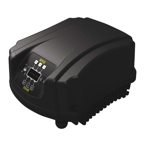
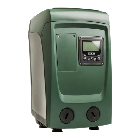
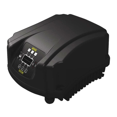
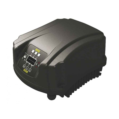
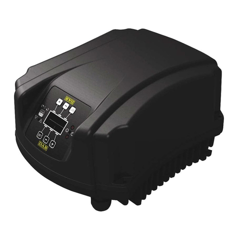
DAB ACTIVE DRIVER PLUS M/T 1.0 Operating and maintenance manual

ISTRUZIONI PER L'INSTALLAZIONE E LA MANUTENZIONE
INSTRUCTIONS FOR INSTALLATION AND MAINTENANCE
INSTRUCTIONS POUR L'INSTALLATION ET LA MAINTENANCE
INSTALLATIONS- UND WARTUNGSANLEITUNGEN
INSTRUCTIES VOOR INSTALLATIE EN ONDERHOUD
INSTRUCCIONES DE INSTALACIÓN Y MANTENIMIENTO
INSTALLATIONS- OCH UNDERHÅLLSANVISNING
ΟΔΗΓΙΕΣ ΓΙΑ ΤΗΝ ΕΓΚΑΤΑΣΤΑΣΗ ΚΑΙ ΤΗ ΣΥΝΤΗΡΗΣΗ
KURMA VE BAKIM BİLGİLERİ
NÁVOD NA INŠTALÁCIU A ÚDRŽBU
РУКОВОДСТВО ПО МОНТАЖУ ИТЕХНИЧЕСКОМУ ОБСЛУЖИВАНИЮ
INSTRUCTIUNI PENTRU INSTALARE SI INTRETINERE
INSTRUÇÕES PARA A INSTALAÇÃO E A MANUTENÇÃO
ASENNUS- JA HUOLTO-OHJEET
INSTRUKCJA MONTAŻU I KONSERWACJI
ІНСТРУКЦІЇ ЗІ ВСТАНОВЛЕННЯ ТА ТЕХНІЧНОГО ОБСЛУГОВУВАННЯ
NÁVOD K INSTALACI A ÚDRŽBĚ
ACTIVE DRIVER PLUS M/T 1.0
ACTIVE DRIVER PLUS M/T 2.2
ACTIVE DRIVER PLUS T/T 3
ACTIVE DRIVER PLUS T/T 5.5
ACTIVE DRIVER PLUS M/M 1.1
ACTIVE DRIVER PLUS M/M 1.8 / DV
ACTIVE DRIVER PLUS M/M 1.5 / DV

Manuale valido per le versioni firmware 1.x (IT)
Manual valid for firmware versions 1.x (GB)
Manuel valide pour les versions micrologiciel 1.x (FR)
Gültiges Handbuch für die Firmware-Versionen 1.x (DE)
Handleiding geldig voor de firmware-versies 1.x (NL)
Manual válido para las versiones firmware 1.x (ES)
Bruksanvisning för programvaruversioner 1.x (SE)
Το εγχειρίδιο ισχύει για τις εκδόσεις firmware 1.x (GR)
Donanım yazılımının 4.x-1.x versiyonlarıiçin geçerli el kitabı(TR)
Príručka platná per verzie firmware 1.x (SK)
Руководство действительно для редакции зашитой программы 1.x (RU)
Manual valabil pentru versiunile firmware 1.x (RO)
Manual válido para as versões firmware 1.x (PT)
Käyttöopas laiteohjelmaversioille 1.x (FI)
Instrukcja obowiązuje dla wersji firmware 1.x (PL)
Керівництво зінструкціями дійсне для версії firmware 1.x (UA)
Tato příručka je platná pro verze firmwaru 1.x (CZ)
(يبرع)

ITALIANO
pag. 01
ENGLISH
page 47
FRANÇAIS
page 93
DEUTSCH
seite 140
NEDERLANDS
pag. 187
ESPAÑOL
pág. 234
SVENSKA
sid. 280
σελίδα 325
TÜRKÇE
sf. 372
SLOVENSKO
stran. 418
стр. 464
ROMÂN
pag. 512
PORTUGUÊS
pag. 558
SUOMI
sivu 604
POLSKI
strona 649
стор. 697
EŠTINA
strana 744
789 ةحفص يبرع

ITALIANO
1
INDICE
LEGENDA..........................................................................................................................................................5
AVVERTENZE ...................................................................................................................................................5
Avvertenze particolari ................................................................................................................................. 6
RESPONSABILITA’ ..........................................................................................................................................6
1GENERALITA’............................................................................................................................................6
1.1Applicazioni........................................................................................................................................7
1.2Caratteristiche tecniche....................................................................................................................7
2INSTALLAZIONE .......................................................................................................................................9
2.1Collegamenti idraulici .......................................................................................................................9
2.1.1 Installazione con pompa singola..................................................................................................... 10
2.1.2 Installazione multipompa ................................................................................................................ 10
2.2Collegamenti elettrici ......................................................................................................................10
2.2.1Collegamento della pompa per i modelli M/T e T/T ................................................................... 11
2.2.2Collegamento della pompa per i modelli M/M ............................................................................ 11
2.3Collegamento alla linea di alimentazione......................................................................................11
2.3.1Collegamento all’alimentazione per i modelli M/T e M/M........................................................... 12
2.3.2Collegamento all’alimentazione per i modelli T/T....................................................................... 12
2.3.3Collegamento degli ingressi utente ............................................................................................ 13
2.3.4Collegamento delle uscite utente ............................................................................................... 15
2.3.5Collegamento del sensore di pressione remoto......................................................................... 15
2.3.6Collegamento della comunicazione multi inverter...................................................................... 15
2.4Configurazione dell’inverter integrato...........................................................................................16
2.5Adescamento ...................................................................................................................................16
2.6Funzionamento ................................................................................................................................17
3LA TASTIERA E IL DISPLAY..................................................................................................................17
3.1Menù..................................................................................................................................................18
3.2Accesso ai menù .............................................................................................................................18
3.2.1 Accesso diretto con combinazione di tasti...................................................................................... 18
3.2.2 Accesso per nome tramite menù a tendina .................................................................................... 20
3.3Struttura delle pagine di menù.......................................................................................................21
3.4Blocco impostazione parametri tramite Password......................................................................22
3.5Abilitazione disabilitazione motore ...............................................................................................22
4SISTEMA MULTI INVERTER...................................................................................................................23
4.1Introduzione ai sistemi multi inverter............................................................................................23
4.2Realizzazione di un impianto multi inverter..................................................................................23
4.2.1 Comunicazione ............................................................................................................................... 23
4.2.2 Sensore remoto in impianti multi inverter ....................................................................................... 23
4.2.3 Collegamento e impostazione degli ingressi fotoaccoppiati........................................................... 23
4.3Parametri legati al funzionamento multi inverter ......................................................................... 24
4.3.1 Parametri di interesse per il multi inverter ...................................................................................... 24
4.3.1.1 Parametri con significato locale ............................................................................................... 24
4.3.1.2 Parametri sensibili.................................................................................................................... 24
4.3.1.3 Parametri con allineamento facoltativo .................................................................................... 24
4.4Primo avvio di un sistema multi-inverter ......................................................................................25
4.5Regolazione multi-inverter .............................................................................................................25
4.5.1 Assegnazione dell'ordine di partenza............................................................................................. 25
4.5.1.1 Tempo massimo di lavoro ........................................................................................................ 25
4.5.1.2 Raggiungimento del tempo massimo di inattività..................................................................... 25
4.5.2 Riserve e numero di inverter che partecipano al pompaggio ......................................................... 26
5ACCENSIONE E MESSA IN OPERA ......................................................................................................26
5.1Operazioni di prima accensione ....................................................................................................26
5.2Wizard ...............................................................................................................................................26
5.2.1 Impostazione della lingua LA.......................................................................................................... 26
5.2.2 Impostazione del sistema di misura MS ......................................................................................... 27
5.2.3 Impostazione del setpoint di pressione SP..................................................................................... 27
5.2.4 Impostazione della frequenza nominale della pompa FN .............................................................. 27
5.2.5 Impostazione della tensione nominale della pompa UN ............................................................... 27
5.2.6 Impostazione della corrente nominale RC...................................................................................... 27
5.2.7 Impostazione del senso di rotazione RT ........................................................................................ 27
5.2.8 Impostazione di altri parametri........................................................................................................ 27

ITALIANO
2
5.3Risoluzione dei problemi tipici alla prima installazione..............................................................28
6SIGNIFICATO DEI SINGOLI PARAMETRI .............................................................................................29
6.1Menù Utente .....................................................................................................................................29
6.1.1 FR: Visualizzazione della frequenza di rotazione........................................................................... 29
6.1.2 VP: Visualizzazione della pressione............................................................................................... 29
6.1.3 C1: Visualizzazione della corrente di fase...................................................................................... 29
6.1.4 PO: Visualizzazione della potenza assorbita.................................................................................. 29
6.1.5 PI: Istogramma della potenza ........................................................................................................ 29
6.1.6 SM: Monitor di sistema ................................................................................................................... 29
6.1.7 VE: Visualizzazione della versione................................................................................................. 30
6.2Menù Monitor ...................................................................................................................................30
6.2.1 VF: Visualizzazione del flusso ........................................................................................................ 30
6.2.2 TE: Visualizzazione della temperatura dei finali di potenza ........................................................... 30
6.2.3 BT: Visualizzazione della temperatura della scheda elettronica .................................................... 30
6.2.4 FF: Visualizzazione storico fault ..................................................................................................... 30
6.2.5 CT: Contrasto display ..................................................................................................................... 30
6.2.6 LA: Lingua....................................................................................................................................... 30
6.2.7 HO: Ore di funzionamento .............................................................................................................. 30
6.2.8 EN: Contatore dell’energia assorbita.............................................................................................. 30
6.2.9 SN: Numero di avvii ........................................................................................................................ 31
6.3Menù Setpoint..................................................................................................................................31
6.3.1 SP: Impostazione della pressione di setpoint................................................................................. 31
6.3.2 Impostazione delle pressioni ausiliarie ........................................................................................... 31
6.3.2.1 P1: Impostazione della pressione ausiliaria 1.......................................................................... 31
6.3.2.2 P2: Impostazione della pressione ausiliaria 2.......................................................................... 31
6.3.2.3 P3: Impostazione della pressione ausiliaria 3.......................................................................... 31
6.4Menù Manuale ..................................................................................................................................31
6.4.1 FP: Impostazione della frequenza di prova .................................................................................... 32
6.4.2 VP: Visualizzazione della pressione............................................................................................... 32
6.4.3 C1: Visualizzazione della corrente di fase...................................................................................... 32
6.4.4 PO: Visualizzazione della potenza assorbita.................................................................................. 32
6.4.5 RT: Impostazione del senso di rotazione ....................................................................................... 32
6.4.6 VF: Visualizzazione del flusso ........................................................................................................ 32
6.5Menù Installatore .............................................................................................................................32
6.5.1 RC: Impostazione della corrente nominale dell'elettropompa ........................................................ 32
6.5.2 RT: Impostazione del senso di rotazione ....................................................................................... 32
6.5.3 FN: Impostazione della frequenza nominale .................................................................................. 33
6.5.4 UN: Impostazione della tensione nominale .................................................................................... 33
6.5.5 OD: Tipologia di impianto .............................................................................................................. 33
6.5.6 RP: Impostazione della diminuzione di pressione per ripartenza................................................... 33
6.5.7 AD: Configurazione indirizzo .......................................................................................................... 33
6.5.8 PR: Sensore di pressione ............................................................................................................... 34
6.5.9 MS: Sistema di misura.................................................................................................................... 34
6.5.10 SX: Setpoint massimo .................................................................................................................. 34
6.6Menù Assistenza Tecnica ...............................................................................................................34
6.6.1 TB: Tempo di blocco mancanza acqua .......................................................................................... 34
6.6.2 T1: Tempo di spegnimento dopo il segnale bassa pressione ........................................................ 34
6.6.3 T2: Ritardo di spegnimento............................................................................................................. 35
6.6.4 GP: Coefficiente di guadagno proporzionale.................................................................................. 35
6.6.5 GI: Coefficiente di guadagno integrale ........................................................................................... 35
6.6.6 FS: Frequenza massima di rotazione............................................................................................. 35
6.6.7 FL: Frequenza minima di rotazione ................................................................................................ 35
6.6.8 Impostazione del numero di inverter e delle riserve...................................................................... 35
6.6.8.1 NA: Inverter attivi...................................................................................................................... 35
6.6.8.2 NC: Inverter contemporanei..................................................................................................... 35
6.6.8.3 IC: Configurazione della riserva............................................................................................... 36
6.6.8.4 Esempi di configurazione per impianti multi inverter................................................................ 36
6.6.9 ET: Tempo di scambio.................................................................................................................... 36
6.6.10 CF: Portante.................................................................................................................................. 37
6.6.11 AC: Accelerazione ........................................................................................................................ 37
6.6.12 AY: Anti cycling............................................................................................................................. 37
6.6.13 AE: Abilitazione della funzione antibloccaggio ............................................................................. 37

ITALIANO
3
6.6.14 AF: Anti freeze .............................................................................................................................. 37
6.6.15 Setup degli ingressi digitali ausiliari IN1, IN2, IN3........................................................................ 37
6.6.15.1 Disabilitazione delle funzioni associate all'ingresso............................................................... 38
6.6.15.2 Impostazione funzione galleggiante esterno.......................................................................... 38
6.6.15.3 Impostazione funzione ingresso pressione ausiliaria............................................................. 39
6.6.15.4 Impostazione abilitazione del sistema e ripristino fault.......................................................... 39
6.6.15.5 Impostazione della rilevazione di bassa pressione (KIWA) ................................................... 40
6.6.16 Setup delle uscite OUT1, OUT2 ................................................................................................... 40
6.6.16.1 O1: Impostazione funzione uscita 1....................................................................................... 41
6.6.16.2 O2: Impostazione funzione uscita 2........................................................................................ 41
6.6.17 SF: Frequenza di avviamento....................................................................................................... 41
6.6.18 ST: Tempo di avviamento............................................................................................................. 41
6.6.19 RF: Reset dello storico dei fault e warning ................................................................................... 41
6.6.20 PW: Modifica password ................................................................................................................ 41
6.6.21 Password sistemi multi inverter .................................................................................................... 42
7SISTEMI DI PROTEZIONE ......................................................................................................................42
7.1Sistemi di protezione.......................................................................................................................43
7.1.1 Anti freeze (protezione contro il congelamento dell’acqua nel sistema) ........................................ 43
7.2Descrizione dei blocchi...................................................................................................................43
7.2.1 “BL” Blocco per mancanza acqua................................................................................................... 43
7.2.2 “BP1” Blocco per guasto sul sensore di pressione......................................................................... 43
7.2.3 "LP" Blocco per tensione di alimentazione bassa .......................................................................... 43
7.2.4 "HP" Blocco per tensione di alimentazione interna alta.................................................................. 43
7.2.5 "SC" Blocco per corto circuito diretto tra le fasi del morsetto di uscita........................................... 43
7.3Reset manuale delle condizioni di errore......................................................................................43
7.4Autoripristino delle condizioni di errore .......................................................................................43
8RESET E IMPOSTAZIONI DI FABBRICA...............................................................................................44
8.1Reset generale del sistema ............................................................................................................44
8.2Impostazioni di fabbrica .................................................................................................................44
8.3Ripristino delle impostazioni di fabbrica ......................................................................................44
9Aggiornamento del firmware .................................................................................................................46
9.1Generalità .........................................................................................................................................46
9.2Aggiornamento ................................................................................................................................46
INDICE DELLE TABELLE
Tabella 1: Famiglie prodotti ........................................................................................................................ 5
Tabella 2: Dati tecnici e limiti di utilizzo ...................................................................................................... 8
Tabella 3: Sezione dei cavi di alimentazione per inverter M/M e M/T...................................................... 12
Tabella 4: Sezione del cavo 4 conduttori (3 fasi + terra) .......................................................................... 12
Tabella 5: Collegamento ingressi ............................................................................................................. 13
Tabella 6: Caratteristiche degli ingressi.................................................................................................... 15
Tabella 7: Collegamento delle uscite........................................................................................................ 15
Tabella 8: Caratteristiche dei contatti di uscita ......................................................................................... 15
Tabella 9: Collegamento del sensore di pressione remoto ...................................................................... 15
Tabella 10: Collegamento della comunicazione multi inverter ................................................................. 16
Tabella 11: Funzioni tasti.......................................................................................................................... 17
Tabella 12: Accesso ai menù.................................................................................................................... 18
Tabella 13: Struttura menù ....................................................................................................................... 20
Tabella 14: Messaggi di stato ed errore nella pagina principale .............................................................. 22
Tabella 15: Indicazioni nella barra di stato ............................................................................................... 22
Tabella 16: Wizard.................................................................................................................................... 26
Tabella 17: Risoluzione dei problemi........................................................................................................ 28
Tabella 18: Visualizzazione del monitor di sistema SM............................................................................ 29
Tabella 19: Impostazione del sensore di pressione remoto ..................................................................... 34
Tabella 20: Sistema di unità di misura...................................................................................................... 34
Tabella 21: Configurazioni di fabbrica degli ingressi ................................................................................ 37
Tabella 22: Configurazioni degli ingressi.................................................................................................. 38
Tabella 23: Funzione galleggiante esterno............................................................................................... 38
Tabella 24: Setpoint ausiliario................................................................................................................... 39
Tabella 25: Abilitazione sistema e ripristino dei fault................................................................................ 40
Tabella 26: Rilevazione del segnale di bassa pressione (KIWA) ............................................................. 40
Tabella 27: Configurazioni di fabbrica delle uscite ................................................................................... 40
Tabella 28: Configurazioni di fabbrica delle uscite ................................................................................... 41

ITALIANO
4
Tabella 29: Allarmi .................................................................................................................................... 42
Tabella 30: Indicazioni dei blocchi ............................................................................................................ 42
Tabella 31: Autoripristino dai blocchi ........................................................................................................ 44
Tabella 32: Impostazioni di fabbrica ......................................................................................................... 45
INDICE DELLE FIGURE
Figura 1: Installazione idraulica ................................................................................................................ 10
Figura 2: Connessione degli ingressi........................................................................................................ 14
Figura 3: Connessione delle uscite........................................................................................................... 15
Figura 4: Connessione della comunicazione multi inverter ...................................................................... 16
Figura 5: Primo adescamento................................................................................................................... 16
Figura 6: Aspetto dell'interfaccia utente.................................................................................................... 17
Figura 7: Selezione dei menù a tendina ................................................................................................... 20
Figura 8: Schema dei possibili accessi ai menù....................................................................................... 21
Figura 9: Visualizzazione di un parametro di menù.................................................................................. 22
Figura 10: Istogramma della potenza ....................................................................................................... 29
Figura 11: Impostazione della pressione di ripartenza ............................................................................. 33

ENGLISH
47
INDEX
KEY..................................................................................................................................................................51
WARNINGS .....................................................................................................................................................51
Special warnings....................................................................................................................................... 52
RESPONSIBILITY ...........................................................................................................................................52
1GENERAL INFORMATION......................................................................................................................52
1.1Applications .....................................................................................................................................53
1.2Technical specifications.................................................................................................................53
2INSTALLATION........................................................................................................................................55
2.1Hydraulic connection......................................................................................................................55
2.1.1 Single pump installation.................................................................................................................. 56
2.1.2 Multipump installation ..................................................................................................................... 56
2.2Electrical connections.....................................................................................................................56
2.2.1Pump connection for M/T and T/T models ................................................................................. 57
2.2.2Pump connection for M/M models.............................................................................................. 57
2.3CONNECTION TO THE POWER SUPPLY LINE.............................................................................57
2.3.1Connection to the power supply for M/T and M/M models......................................................... 58
2.3.2Connection to the power supply for T/T models......................................................................... 58
2.3.3Connection of user inputs........................................................................................................... 59
2.3.4Connection of the user outputs .................................................................................................. 61
2.3.5Connection of the remote sensor ............................................................................................... 61
2.3.6Connection of the multi-inverter communication ........................................................................ 62
2.4Configuration of the Integrated Inverter........................................................................................62
2.5Priming .............................................................................................................................................62
2.6Operation..........................................................................................................................................63
3KEYBOARD AND DISPLAY....................................................................................................................63
3.1Menus ...............................................................................................................................................64
3.2Access to menus.............................................................................................................................64
3.2.1 Direct access with button combinations ......................................................................................... 64
3.2.2 Access by name via drop-down menus.......................................................................................... 66
3.3Structure of menu pages ................................................................................................................67
3.4Parameter setting block via Password..........................................................................................68
3.5Enabling and disabling the motor..................................................................................................69
4MULTI INVERTER SYSTEM....................................................................................................................69
4.1Introduction to multi inverter systems..........................................................................................69
4.2Setting up a multi inverter system.................................................................................................69
4.2.1 Communication............................................................................................................................... 69
4.2.2 Remote sensor in multi-inverter systems ....................................................................................... 69
4.2.3 Connection and setting of the optical coupling inputs .................................................................... 69
4.3Multi inverter operating parameters..............................................................................................70
4.3.1 Parameters related to multi inverter systems ................................................................................. 70
4.3.1.1 Local parameters...................................................................................................................... 70
4.3.1.2 Sensitive parameters ............................................................................................................... 70
4.3.1.3 Parameters with optional alignment......................................................................................... 71
4.4Initial start-up of multiple inverter system....................................................................................71
4.5Multi-inverter settings.....................................................................................................................71
4.5.1 Assigning the start-up order............................................................................................................ 71
4.5.1.1 Maximum operating time.......................................................................................................... 71
4.5.1.2 Reaching of maximum inactivity time....................................................................................... 72
4.5.2 Reserves and number of inverters involved in pumping ................................................................ 72
5POWER-UP AND START-UP..................................................................................................................72
5.1Initial power-up operations.............................................................................................................72
5.2Wizard...............................................................................................................................................72
5.2.1 Setting the language LA ................................................................................................................. 73
5.2.2 Setting the measurement system MS............................................................................................. 73
5.2.3 Setting the pressure setpoint SP .................................................................................................... 73
5.2.4 Setting the rated frequency of the pump FN................................................................................... 73
5.2.5 Setting the rated voltage of the pump UN ...................................................................................... 73
5.2.6 Setting the rated current RC........................................................................................................... 73
5.2.7 Setting the direction of rotation RT ................................................................................................. 73
5.2.8 Setting other parameters ................................................................................................................ 73
5.3Troubleshooting on initial installation ..........................................................................................74

ENGLISH
48
6KEY TO INDIVIDUAL PARAMETERS.....................................................................................................75
6.1User menu ........................................................................................................................................75
6.1.1 FR: Display of rotation frequency ................................................................................................... 75
6.1.2 VP: Display of pressure .................................................................................................................. 75
6.1.3 C1: Display of phase current .......................................................................................................... 75
6.1.4 PO: Display of the power delivered ................................................................................................ 75
6.1.5 PI: Power histogram ....................................................................................................................... 75
6.1.6 SM: System monitor ....................................................................................................................... 75
6.1.7 VE: Display of version..................................................................................................................... 75
6.2Monitor menu...................................................................................................................................76
6.2.1 VF: Flow display.............................................................................................................................. 76
6.2.2 TE: Display of final power stage temperature................................................................................. 76
6.2.3 BT: Display of electronic board temperature .................................................................................. 76
6.2.4 FF: Display of fault log .................................................................................................................... 76
6.2.5 CT: Display contrast ....................................................................................................................... 76
6.2.6 LA: Language.................................................................................................................................. 76
6.2.7 HO: Operating hours....................................................................................................................... 76
6.2.8 EN: absorbed energy counter......................................................................................................... 76
6.2.9 SN: Number of starts ...................................................................................................................... 77
6.3Setpoint menu..................................................................................................................................77
6.3.1 SP: Setting the setpoint pressure ................................................................................................... 77
6.3.2 Auxiliary pressure settings.............................................................................................................. 77
6.3.2.1 P1: Auxiliary pressure 1 setting................................................................................................ 77
6.3.2.2 P2: Auxiliary pressure 2 setting................................................................................................ 77
6.3.2.3 P3: Auxiliary pressure 3 setting................................................................................................ 77
6.4Manual menu....................................................................................................................................77
6.4.1 FP: Test frequency setting.............................................................................................................. 78
6.4.2 VP: Display of pressure .................................................................................................................. 78
6.4.3 C1: Display of phase current .......................................................................................................... 78
6.4.4 PO: Display of the power delivered ................................................................................................ 78
6.4.5 RT: Setting the direction of rotation ................................................................................................ 78
6.4.6 VF: Flow display.............................................................................................................................. 78
6.5Installer menu ..................................................................................................................................78
6.5.1 RC: Electric pump rated current setting.......................................................................................... 78
6.5.2 RT: Setting the direction of rotation ................................................................................................ 78
6.5.3 FN: Rated frequency settings ......................................................................................................... 79
6.5.4 UN: Setting the rated voltage.......................................................................................................... 79
6.5.5 OD: Type of system ........................................................................................................................ 79
6.5.6 RP: Setting the pressure drop for restart........................................................................................ 79
6.5.7 AD: Address configuration .............................................................................................................. 79
6.5.8 PR: Pressure sensor....................................................................................................................... 79
6.5.9 MS: Measurement system .............................................................................................................. 80
6.5.10 SX: Setpoint massimo .................................................................................................................. 80
6.6Technical Assistance Menu............................................................................................................80
6.6.1 TB: Water failure block time............................................................................................................ 80
6.6.2 T1: Shutdown time after low pressure signal.................................................................................. 80
6.6.3 T2: Shutdown delay ........................................................................................................................ 80
6.6.4 GP: Proportional gain coefficient .................................................................................................... 80
6.6.5 GI: Integral gain coefficient ............................................................................................................. 81
6.6.6 FS: Maximum rotation frequency.................................................................................................... 81
6.6.7 FL: Minimum rotation frequency ..................................................................................................... 81
6.6.8 Setting the number of inverters and reserves................................................................................ 81
6.6.8.1 NA: Active inverters.................................................................................................................. 81
6.6.8.2 NC: Simultaneous inverters ..................................................................................................... 81
6.6.8.3 IC: Reserve configuration......................................................................................................... 81
6.6.8.4 Examples of configuration for multi-inverter systems .............................................................. 82
6.6.9 ET: Exchange time ......................................................................................................................... 82
6.6.10 CF: Carrier frequency ................................................................................................................... 82
6.6.11 AC: Acceleration ........................................................................................................................... 82
6.6.12 AY: Anti cycling............................................................................................................................. 82
6.6.13 AE: Enabling the anti-blocking function ........................................................................................ 83
6.6.14 AF: Anti freeze .............................................................................................................................. 83
ENGLISH
49
6.6.15 Setup of auxiliary digital inputs IN1, IN2, IN3, IN4........................................................................ 83
6.6.15.1 Disabling functions associated with input .............................................................................. 84
6.6.15.2 Setting the external float function........................................................................................... 84
6.6.15.3 Setting the auxiliary pressure input function .......................................................................... 84
6.6.15.4 Setting the system enable and fault reset.............................................................................. 85
6.6.15.5 Setting low pressure detection (KIWA) .................................................................................. 86
6.6.16 Setup of outputs OUT1, OUT2 ..................................................................................................... 86
6.6.16.1 O1: Output 1 function setting ................................................................................................. 86
6.6.16.2 O2: Output 2 function setting .................................................................................................. 86
6.6.17 SF: Starting frequency .................................................................................................................. 87
6.6.18 ST: Starting time ........................................................................................................................... 87
6.6.19 RF: Fault and warning log reset.................................................................................................... 87
6.6.20 PW: Change password ................................................................................................................. 87
6.6.21 Password for multipump systems................................................................................................. 88
7PROTECTION SYSTEMS........................................................................................................................88
7.1Protection systems..........................................................................................................................88
7.1.1 Anti-Freeze (Protection against freezing of water in the system)................................................... 88
7.2Description of blocks......................................................................................................................89
7.2.1 “BL” Block due to water failure........................................................................................................ 89
7.2.2 “BP1” Block due to fault on pressure sensor .................................................................................. 89
7.2.3 "LP" Block due to low power supply voltage................................................................................... 89
7.2.4 "HP" Block due to high internal power supply voltage.................................................................... 89
7.2.5 "SC" Block due to direct short circuit between the phases on the output terminal......................... 89
7.3Manual reset of error conditions....................................................................................................89
7.4Auto-reset of error conditions........................................................................................................89
8RESET AND FACTORY SETTINGS........................................................................................................90
8.1General system reset ......................................................................................................................90
8.2Factory settings...............................................................................................................................90
8.3Restoring the factory settings........................................................................................................90
9Firmware update.....................................................................................................................................92
9.1General .............................................................................................................................................92
9.2Update...............................................................................................................................................92
INDEX OF TABLE
Table 1: Product families .......................................................................................................................... 51
Table 2: Technical data and limitations of use ......................................................................................... 54
Table 3: Section of power cables for M/M and M/T inverters ................................................................... 58
Table 4: Section of 4-wire cable (3 phases + earth)................................................................................. 58
Table 5: Input connection ......................................................................................................................... 59
Table 6: Input specifications ..................................................................................................................... 61
Table 7: Output connection....................................................................................................................... 61
Table 8: Output contact specifications...................................................................................................... 61
Table 9: Connection of the remote pressure sensor ................................................................................ 61
Table 10: Connection of the multi-inverter communication ...................................................................... 62
Table 11: Button functions ........................................................................................................................ 63
Table 12: Access to menus ...................................................................................................................... 64
Table 13: Menu structure.......................................................................................................................... 66
Table 14: Error status messages on main page....................................................................................... 68
Table 15: Status bar indications ............................................................................................................... 68
Table 16: Wizard....................................................................................................................................... 72
Table 17: Troubleshooting ........................................................................................................................ 74
Table 18: Display of SM system monitor .................................................................................................. 75
Table 19: Setting of the remote pressure sensor ..................................................................................... 80
Table 20: Unit of measurement system.................................................................................................... 80
Table 21: Default settings of inputs .......................................................................................................... 83
Table 22: Input configuration .................................................................................................................... 84
Table 23: External float function ............................................................................................................... 84
Table 24: Auxiliary setpoints..................................................................................................................... 85
Table 25: System enable and fault reset .................................................................................................. 85
Table 26: Low pressure signal detection (KIWA) ..................................................................................... 86
Table 27: Default output settings.............................................................................................................. 86
Table 28: Output configuration ................................................................................................................. 87
Table 29: Allarms...................................................................................................................................... 88

ENGLISH
50
Table 30: Block information ...................................................................................................................... 88
Table 31: Auto-reset of blocks .................................................................................................................. 90
Table 32: Factory settings ........................................................................................................................ 91
INDEX OF FIGURES
Figure 1: Hydraulic installation.................................................................................................................. 56
Figure 2: Input connection ........................................................................................................................ 60
Figure 3: Output connection ..................................................................................................................... 61
Figure 4: Connection of the multi-inverter communication ....................................................................... 62
Figure 6: Appearance of the user interface .............................................................................................. 63
Figure 7: Drop-down menu selection........................................................................................................ 66
Figure 8: Optional menu access scheme ................................................................................................. 67
Figure 9: Menu parameter display............................................................................................................ 68
Figure 10: Power histogram...................................................................................................................... 75
Figure 11: Setting the restart pressure ..................................................................................................... 79

ENGLISH
51
KEY
In this document, the following symbols have been used:
General danger. Failure to observe the warnings alongside this symbol can cause damage or physical
injury.
Risk of electric shock. Failure to observe the warnings alongside this symbol can cause serious hazards
with risk to personal safety.
Notes
WARNINGS
This manual refers to the products
Active Driver Plus M/T 1.0
Active Driver Plus M/T 2.2
Active Driver Plus T/T 3
Active Driver Plus T/T 5.5
Active Driver Plus M/M 1.1
Active Driver Plus M/M 1.8 / DV
Active Driver Plus M/M 1.5 / DV
The above products can be classified in families according to their characteristics.
The subdivision by family is as follows:
Family Product
M/T ACTIVE DRIVER PLUS M/M 1.1
ACTIVE DRIVER PLUS M/M 1.5 / DV
T/T ACTIVE DRIVER PLUS M/M 1.8 / DV
ACTIVE DRIVER PLUS M/T 1.0
M/M
ACTIVE DRIVER PLUS M/T 2.2
ACTIVE DRIVER PLUS T/T 3
ACTIVE DRIVER PLUS T/T 5.5
Table 1: Product families
In the discussion below, the term “inverter” will be used when the characteristics are common to all models. If the
characteristics differ, the family or product concerned will be specified.
Read this documentation carefully before installation.
Installation and operation must comply with the local safety regulations in force in the country in which the
product is installed. Everything must be done in a workmanlike manner.
Failure to respect the safety regulations not only causes risk to personal safety and damage to the
equipment, but invalidates every right to assistance under guarantee.
Skilled personnel
It is advisable that installation be carried out by competent, skilled personnel in possession of the
technical qualifications required by the specific legislation in force.
The term skilled personnel means persons whose training, experience and instruction, as well as their
knowledge of the respective standards and requirements for accident prevention and working conditions,
have been approved by the person in charge of plant safety, authorizing them to perform all the nec-
essary activities, during which they are able to recognize and avoid all dangers. (Definition for technical
personnel IEC 364). The appliance is not intended to be used by persons (including children) with
reduced physical, sensory or mental capacities, or who lack experience or knowledge, unless, through
the mediation of a person responsible for their safety, they have had the benefit of supervision or of
instructions on the use of the appliance. Children must be supervised to ensure that they do not play with
the appliance.

ENGLISH
52
Safety
Use is allowed only if the electric system is in possession of safety precautions in accordance with the regulations
in force in the country where the product is installed (for Italy CEI 64/2).
Pumped liquids
The machine has been designed and made for pumping water, free from explosive substances and solid
particles or fibres, with a density of 1000 Kg/m³, a kinematic viscosity of 1mm²/s and non chemically
aggressive liquids.
The power supply cable must never be used to carry or shift the pump.
Never pull on the cable to detach the plug from the socket.
If the power cable is damaged, it must be replaced by the manufacturer or by their authorised technical
assistance service, so as to avoid any risk.
Failure to observe the warnings may create situations of risk for persons or property and will void the product
guarantee.
Special warnings
Before working on the electrical or mechanical part of the system, always turn off the mains
voltage. Wait at least five minutes after the power supply to the machine has been switched
off before opening the appliance. The capacitor of the continuous intermediate circuit
remains charged with dangerously high voltage even after the mains voltage has been
switched off.Only firmly wired mains connections are admissible. The appliance must be earthed (IEC
536 class 1, NEC and other relevant standards).
Mains and motor terminals may carry dangerous voltage even when the motor is stopped.
In specific calibration conditions, after a power failure the converter may start automatically.
Do not operate the appliance when exposed to direct sunlight.
This appliance may not be used as an “EMERGENCY STOP mechanism” (see EN 60204, 9.2.5.4).
RESPONSIBILITY
The Manufacturer does not vouch for correct operation of the electropumps or answer for any damage that
they may cause if they have been tampered with, modified and/or run outside the recommended work range
or in contrast with other indications given in this manual.
The Manufacturer declines all responsibility for possible errors in this instructions manual, if due to misprints or errors
in copying. The Manufacturer reserves the right to make any modifications to products that it may consider necessary
or useful, without affecting their essential characteristics.
1 GENERAL INFORMATION
Inverter for electropumps designed for pressure boosting in hydraulic plants by measuring the pressure and the flow.
There are a wide range of operating modes and optional accessories. By means of the various possible settings and
availability of configurable inputs and outputs, operation of the inverter can be adapted to meet the requirements of all
systems. 6 SIGNIFICATO DEI SINGOLI PARAMETRI specifies the various settable values: pressure, protection cut-
out trip, frequency of rotation, etc.
In this manual the pump will also be referred to in the abbreviated form "inverter", when dealing with common
characteristics.

ENGLISH
53
1.1 Applications
Possible applications include:
-homes -well water supply
-apartment blocks -irrigation for greenhouses, gardens, agriculture
-camp sites -re-use of rainwater
-swimming pools -industrial systems
-farms
1.2 Technical specifications
A
ctive
Driver
Plus M/T
1.0
Active
Driver
Plus M/T
2.2
A
ctive
Driver
Plus T/T 3
A
ctive
Driver
Plus T/T
5.5
A
ctive
Driver
Plus M/M
1.1
Active
Driver Plus
M/M 1.8 / DV
A
ctive
Driver Plus
M/M 1.5 / DV
Electric
power
supply
Number of
phases 1 1 3 3 1 1 1
Voltage
[VAC] 1 x
220-240
1 x
220-240
3 x
380-480
3 x
380-480
1 x
220-240
1 x 220-240
/
1 x 110-127
1 x 220-240
/
1 x 110-127
Frequency
[Hz] 50/60 50/60 50/60 50/60 50/60 50/60 50/60
Absorbed
current
[Arms] 10 22 9 16 10 13 17
Leakage
current to
earth [mA] <2 <2 <16 <16 <2 <2 <2
Electro-
pump
Output
Number of
phases 3 3 3 3 1 1 1
Voltage*
[VAC] 3 x
220-240
3 x
220-240
3 x
380-480
3 x
380-480
1 x
220-240
1 x 220-240
/
1 x 110-127
1 x 220-240
/
1 x 110-127
Frequency
[Hz] 50 - 200 50 - 200 50 - 200 50 - 200 50/60 50/60 50/60
Max phase
current
[Arms] 4,7 10,5 7,5 13,3 8,5 11 14
Constructi
on
characteri
stics
Dimensions
(LxHxP)
[mm]
237x282x1
84
237x282x1
84
237x282x1
84
237x282x1
84
237x282x1
84
237x282x18
4
237x282x18
4
Weight
(packing
excluded)
[kg]
3,5 3,5 4,5 4,6 3,5 3,5 3,8
Grade of
protection
IP
55 55 55 55 55 55 55
Hydraulic
performan
-ce
Max
pressure
[bar] 13 13 13 13 13 13 13
Pressure
regulating
range [bar] 1-9 1-13 1-13 1-13 1-9 1-9 1-9
Maximum
flow [l/min] 300 300 300 300 300 300 300

ENGLISH
54
A
ctive
Driver Plus
M/T 1.0
Active
Driver Plus
M/T 2.2
A
ctive
Driver Plus
T/T 3
A
ctive
Driver
Plus T/T
5.5
A
ctive
Driver Plus
M/M 1.1
Active
Driver Plus
M/M 1.8 /
DV
A
ctive
Driver Plus
M/M 1.5 /
DV
Working
conditions
Work
position Any Any Vertical Vertical Any Any Any
Max liquid
temperature
[°C] 50 50 50 50 50 50 50
Max
ambient
temperature
[°C]
50 50 50 50 50 50 50
Hydraulic
conne-
ctions
Fluid input
hydraulic
coupling 1 ¼” male 1 ¼” male 1 ¼” male 1 ¼”
male 1 ¼” male 1 ¼” male 1 ¼” male
Fluid output
hydraulic
coupling
1 ½”
female
1 ½”
female
1 ½”
female
1 ½”
female
1 ½”
female
1 ½”
female
1 ½”
female
Functiona
lity and
prote-
ctions
Connectivity CAN CAN CAN CAN CAN CAN CAN
Dry
operation
protection YES YES YES YES YES YES YES
Overload
protection
to
electropump
YES YES YES YES YES YES YES
Protection
against
excess
temperature
of the
electronics
YES YES YES YES YES YES YES
Protection
against
abnormal
supply
voltages
NO NO YES YES YES YES YES
Protection
against
short circuit
between
phases on
output
YES YES YES YES YES YES YES
Antifreeze
protection YES YES YES YES YES YES YES
Anticycling
protection SI SI SI SI SI SI SI
Digital
inputs 3 3 3 3 1 1 1
Relay
outputs 2 2 2 2 NO NO NO
Remote
pressure
sensor YES YES YES YES YES YES YES
*The output voltage cannot be higher than the power supply voltage
Table 2: Technical data and limitations of use

ENGLISH
55
2 INSTALLATION
The system is designed to be able to work in environments where the temperature remains between 0°C
and 50°C (on condition that the electric power supply is ensured: see par.6.6.14 “anti-freeze function”).
The system is suitable for treating drinking water.
The system cannot be used to pump salt water, sewage, inflammable, corrosive or explosive liquids (e.g.
petroleum, petrol, thinners), greases, oils or food products.
If the system is used for the domestic water supply, respect the local regulations of the authorities
responsible for the management of water resources.
When choosing the installation site, check that:
The voltage and frequency on the pump’s technical data plate correspond to the values of the
power supply system.
The electrical connection is made in a dry place, far from any possible flooding.
The electrical system is provvided with a differential switch sized according to the
characteristics indicated in Table 2
The equipment requires an earth connection.
If you are not sure of the absence of foreign bodies in the water to be pumped, install a filter on the
system intake that is suitable for catching impurities.
The installation of a filter on intake causes a decrease of the system’s hydraulic performance
proportional to the loss of load caused by the filter itself (generally the greater the filtering power, the
greater the fall in performance).
2.1 Hydraulic connection
The Inverter works at constant pressure. This regulation is most appreciated if the hydraulic
system downstream from the system is suitably sized.
Systems made with excessively narrow pipes can cause load losses which the appliance is unable to
compensate for; the result is that the pressure is constant on the device but not on the utility.
RISK OF FROST: pay attention to the installation site of Inverter! Take the following precautions:
If the Inverter is operative it is absolutely necessary to protect it adequately against frost and to leave it
constantly powered. If it is disconnected from the power supply, the anti-frost function is no longer active!
If the Inverter is not operative it is necessary to turn off the power supply, disconnect the appliance
from the pipe and completely empty out all water left inside.
It is not sufficient just to remove pressure from the pipe, because some water is always left inside!
Always install a check valve on the pipe upstream from the Inverter.
For the purposes of operation of the Inverter it does not matter whether the valve is fitted on the suction
or on the delivery of the pump. The hydraulic connection between the Inverter and the electric pump
must not have any derivations. The dimensions of the pipe must be suitable for the electric pump
installed.

ENGLISH
56
2.1.1 Single pump installation
Figure 1 shows a schematic layout of the hydraulic installation of a pump with inverter.
Figure 1: Hydraulic installation
2.1.2 Multipump installation
Our systems allow the possibility of creating multipump booster sets with coordinated control of all the inverters. The
maximum number of elements that can be connected to create a multipump system is 8. To make use of the
coordinated control function (multi-inverter) it is also necessary to make the required electrical connections to put the
inverters in communication with one another see par. 2.3.6.
A multipump system is used mainly for:
• Increasing hydraulic performance in comparison with a single device.
• Ensuring continuity of operation in the event of a device developing a fault.
• Sharing out the maximum power.
The system is created in a similar way to the single pump system: each pump has its own delivery to its own inverter
and the hydraulic outputs of the inverter all flow into a single manifold.
The manifold must be correctly sized to support the flow created by the pumps that you want to use.
The hydraulic plant must be created as symmetrically as possible to obtain a hydraulic load uniformly distributed over
all the pumps.
The pumps must all be the same and the inverters must all be of the same identical model, connected to each other in
a multi-inverter configuration, see par. 2.1.2
2.2 Electrical connections
The inverter is equipped with cables for the power supply and for the pump, indicated respectively with the labels LINE
and PUMP.
The internal electrical connections are accessible by removing the 4 screws on the cover. The internal terminal boards
have the same words LINE and PUMP applied on the cables.
Partsthatmakeupthesystem
1Expansionvessel
2Pressuregauge
3,12Non‐returnvalve
4,11Ballvalve
5,9Couplingwithrapidinlet
6Electropumpconnection
7Lineconnection
8Inverter
10Filter
13Pump

ENGLISH
57
Before performing any installation or maintenance operation, disconnect the inverter from the electrical
mains and wait for at least 15 minutes before touching internal parts Ensure that the voltage and
frequency values on the inverter data plate correspond to those of the power mains.
To improve the immunity to any noise radiated towards other equipment we recommend using separate ducts for the
inverter supply cables.
The installer shall be responsible for checking that the electric power supply system is fitted with an efficient earthing
system according to the regulations in force.
Ensure that all the terminals are fully tightened, paying particular attention to the earth terminal.
Also ensure that the cable clamps are fully secured to guarantee IP55 protection rating.
Check that all the connecting cables are in perfect condition, with the external sheathing unbroken. The motor of the
installed electric pump must comply with the data in Table 2.
Incorrect connection of the earth lines to a terminal other than the earth terminal may cause
irremediable damage to the whole appliance!
Incorrect connection of the power supply line on output terminals intended for the load may
cause irremediable damage to the whole appliance!
2.2.1 Pump connection for M/T and T/T models
The output for the electropump is available on the three-phase cable + earth indicated with the PUMP label.
The motor of the installed electropump must be of the three-phase type with voltage 220-240V for type M/T and 380-
480V for type T/T. To make the correct type of connection of the motor windings, follow the indications on the data
plate or on the terminal board of the electropump.
2.2.2 Pump connection for M/M models
The output for the electropump is available on the single-phase cable + earth indicated with the PUMP label.
Type DV inverters can be connected to motors with power supply 110-127V oppure 220-240V. In order to use the
voltage 220-240V to control the motor in a DV inverter, it is necessary to use a power supply with the same voltage.
For all M/M inverters size 11 and 14 A, ensure that the voltage of the motor used has been correctly
configured, see par. 5.2.5.
M/M inverters size 8.5 A can be connected only to electropumps with a 230V single-phase motor.
2.3 CONNECTION TO THE POWER SUPPLY LINE
CAUTION: The line voltage may change when the electrical pump is started up by the inverter.
The voltage may be subject to variations according to other devices connected, and the quality of the
line.
ATTENTION: The protective circuit breaker and the power cables of the inverter and of the pump must be sized
according to the system.
The differential switch for protecting the system must be correctly sized according to the characteristics indicated in
Table 2. For M/T and M/M inverters it is recommended to use a type F differential switch protected against sudden
tripping. For T/T inverters it is recommended to use a type B differential switch protected against sudden tripping.
If the instructions supplied in this manual are in contrast with the regulations in force the regulations must be
considered as valid
In the case of extensions to the inverter cables, for example for power supply to submersed electric pumps, if there is
electromagnetic disturbance, the following is recommended:
Check earthing and if necessary add an earthing device in the immediate vicinity of the Inverter.
Embed the cables.
Use shielded cables.
Install the DAB Active Shield device.

ENGLISH
58
For correct operation the mains filter must be installed close to the Inverter!
2.3.1 Connection to the power supply for M/T and M/M models
The relative line specifications must correspond to those shown in Table 2.
The section, type and laying of cables for inverter power supply and electric pump connections must be selected in
compliance with current standards. Table 3 provides indications on the cable section to be used. The table refers to
cables in PVC with 3-core cable (phase neutral + earth)with the minimum recommended section based on the current
and length of cable.
Power cable section in mm²
Data for 3-core PVC cables (phase + neutral + earth)
10 m 20 m 30 m 40 m 50 m 60 m 70 m 80 m 90 m 100 m 120 m 140 m 160 m 180 m 200 m
4 A 1,5 1,5 1,5 1,5 2,5 2,5 2,5 2,5 4 4 4 6 6 6 10
8 A 1,5 1,5 2,5 2,5 4 4 6 6 6 10 10 10 10 16 16
12 A 1,5 2,5 4 4 6 6 10 10 10 10 16 16 16
16 A 2,5 2,5 4 6 10 10 10 10 16 16 16
20 A 4 4 6 10 10 10 16 16 16 16
24 A 4 4 6 10 10 16 16 16
28 A 6 6 10 10 16 16 16
Table 3: Section of power cables for M/M and M/T inverters
The current supply to the inverter can generally by estimated (with a relative safety margin) at 2.5 times the current
absorbed by the three-phase pump. For example, if the pump connected to the inverter absorbs 10A per phase, the
inverter power supply cables should be sized for 25A.
Although the inverter is already equipped with internal safety devices, the installation of a suitably sized thermal
magnetic circuit breaker is recommended.
2.3.2 Connection to the power supply for T/T models
The relative line specifications must correspond to those shown in Table 2. The section, type and laying of cables for
inverter power supply and electric pump connections must be selected in compliance with current standards. Table 4
provides indications on the cable section to be used. The table refers to cables in PVC with 4 wires (3 phases+earth)
with the minimum recommended section based on the current and length of cable.
Cable section in mm²
Data for 4-core PVC cables (3 phases + earth))
10 m 20 m 30 m 40 m 50 m 60 m 70 m 80 m 90 m 100 m 120 m 140 m 160 m 180 m 200 m
4 A 1,5 1,5 1,5 1,5 1,5 1,5 1,5 1,5 2,5 2,5 2,5 2,5 4 4 4
8 A 1,5 1,5 1,5 1,5 2,5 2,5 2,5 4 4 4 6 6 6 10 10
12 A 1,5 1,5 2,5 2,5 4 4 4 6 6 6 10 10 10 10 16
16 A 2,5 2,5 2,5 4 4 6 6 6 10 10 10 10 16 16 16
20 A 2,5 2,5 4 4 6 6 10 10 10 10 16 16 16 16 16
24 A 4 4 4 6 6 10 10 10 10 16 16 16 16 16 16
28 A 6 6 6 6 10 10 10 10 16 16 16 16 16 16 16
32 A 6 6 6 6 10 10 10 16 16 16 16 16 16 16 16
36 A 10 10 10 10 10 10 16 16 16 16 16 16 16 16 16
40 A 10 10 10 10 10 16 16 16 16 16 16 16 16 16 16
44 A 10 10 10 10 10 16 16 16 16 16 16 16 16 16 16
48 A 10 10 10 10 16 16 16 16 16 16 16 16 16 16 16
52 A 16 16 16 16 16 16 16 16 16 16 16 16 16 16 16
56 A 16 16 16 16 16 16 16 16 16 16 16 16 16 16 16
60 A 16 16 16 16 16 16 16 16 16 16 16 16 16 16 16
Table 4: Section of 4-wire cable (3 phases + earth)

ENGLISH
59
The current supply to the inverter can normally be calculated (taking a safety margin into account) as 1/8 of the
current absorbed by the pump.
Although the inverter is already equipped with internal safety devices, the installation of a suitably sized thermal
magnetic circuit breaker is recommended.
If the entire power range available is used, for specific information on the current to be used when choosing cables
and the thermal magnetic circuit breaker, refer to Table 4.
2.3.3 Connection of user inputs
In inverters type M/T and T/T, the inputs can be switched on using either direct current or alternating current at 50-60
Hz. In type M/M the input can be activated only with a clean contact inserted between the two pins.
The wiring diagram and the electrical characteristics of the inputs are shown below.
Wiring diagram of user inputs
Type of
inverter Name of
connector Pin Use
M/T J6
1 Power supply terminal: + 12V DC – 50 mA
2 Connection terminal input I3
3 Connection terminal input I2
4 Common connection terminal I3 – I2
5 Connection terminal input I1
6 Common connection terminal I1
7 Connection terminal: GND
T/T J7
1 Power supply terminal: + 12V DC – 50 mA
2 Connection terminal input I3
3 Connection terminal input I2
4 Common connection terminal I3 – I2
5 Connection terminal input I1
6 Common connection terminal I1
7 Connection terminal: GND
M/M J2
1 Connection terminal input I1
2 Connection terminal: GND
Table 5:Input connection
This manual suits for next models
6
Table of contents
Other DAB Inverter manuals

DAB
DAB MCE-22/C Operating and maintenance manual

DAB
DAB MCE-55/C Operating and maintenance manual

DAB
DAB MCE-150/C Operating and maintenance manual

DAB
DAB MCE-55/P Operating and maintenance manual

DAB
DAB MCE-150/P User manual

DAB
DAB PWM II 230 D 4.7 Operating and maintenance manual

DAB
DAB AD 2.2 AC Operating and maintenance manual

DAB
DAB MCE-22/P Operating and maintenance manual

DAB
DAB E.SYBOX MINI 3 Operating and maintenance manual

DAB
DAB MCE-22/C Operating and maintenance manual