Dacor Distinctive DTHP30 User manual

Installation Instructions
Distinctive® Wall Mount Range Hoods
DTHP30, DTHP36, DTHP48
Part No. 109174 Rev. A
APPROVED FOR USE WITH ALL DACOR®RANGES AND COOKTOPS.
TESTED IN ACCORDANCE WITH THE LATEST EDITION OF ANSI/UL 507
STANDARD FOR ELECTRIC FANS AND CAN/CSA-C22.2 NO. 115 STANDARD
FOR FANS AND VENTILATORS.

Planning the Ductwork ..................................................... 9
Preparing the Mounting Location ....................................11
Installation Instructions.................................................. 12
Marking the Centerlines ................................................ 12
Installing the Holding Brackets....................................... 13
Rotating the Fan(s) for Rear Exhaust ............................ 14
Using the Dual to Single Transition Kit# AHT10 ............ 18
Hanging the Range Hood .............................................. 20
Hardwiring the Hood ...................................................... 21
Verifying the Setup......................................................... 23
The Installation Checklist ............................................... 24
Wiring Diagrams.............................................................. 25
Table of Contents
Before You Begin...
Important Safety Instructions .......................................... 1
Important Information About Safety Instructions.............. 1
General Safety Precautions ............................................. 2
Product Specifications .................................................... 3
General Specifications ..................................................... 3
Weight Specifications....................................................... 3
Dimensions ...................................................................... 4
Preparation and Setup...................................................... 6
Parts List .......................................................................... 6
Necessary Tools and Hardware ....................................... 6
Meeting Electrical Codes ................................................. 7
Installing the Electrical Source......................................... 7
Meeting Installation Requirements................................... 8
All specifications subject to change without notice. Dacor assumes no liability for changes to specifications.
© 2008 Dacor, all rights reserved.
Important:
• Installer: In the interest of safety and to minimize problems, read these Installation Instructions completely and
carefully before you begin the installation process. Leave these installation instructions with the consumer.
Write the Data Plate Information in the Use and Care Manual before installing the unit.
• Customer: Keep these Installation Instructions for future reference and the local electrical inspector’s use.
If You Need Help...
If you have questions or problems with installation, contact your Dacor dealer or
the Dacor Customer Service Team. For repairs to Dacor appliances under war-
ranty call the Dacor Distinctive Service line. Whenever you call, have the model
and serial number of the appliance ready. The model and serial number are
printed on the appliance data plate.
Dacor Customer Service Team
Phone: (800) 793-0093 ex. 2813 (U.S.A. and Canada)
Monday — Friday 6:00 a.m.to 5:00 p.m.Pacific Time
Website: www.dacor.com
Dacor Distinctive Service (for repairs under warranty only)
Phone: (800) 793-0093 ex. 2822 (U.S.A. and Canada)
Monday — Friday 6:00 a.m.to 5:00 p.m.Pacific Time
Appliance Data Plate
The appliance data plate is a label that:
• has the model and serial number information and electrical requirements.
• is located inside the hood, above the filters on the back wall of the chassis.
Remove the filters to view it.

1
Important Information About
Safety Instructions
• The Important Safety Instructions and warnings in
these instructions are not meant to cover all possible
problems and conditions that can occur. Use common
sense and caution when installing, maintaining or oper-
ating this or any other appliance.
• Always contact the Dacor Customer Service Team
about problems and conditions that you don’t under-
stand.
Important Safety Instructions
Safety Symbols and Labels
DANGER
Immediate hazards that WILL result in severe personal
injury or death.
WARNING
Hazards or unsafe practices that COULD result in severe
personal injury or death.
CAUTION
Hazards or unsafe practices that MIGHT result in minor
personal injury or property damage.
DANGER
To avoid the possibility of explosion or fire, do not store or use combustible, flammable or explosive vapors and liquids
(such as gasoline) inside or in the vicinity of this or any other appliance. Also keep items that could explode, such as
aerosol cans away from cooktop burners, ovens and range hoods. Do not store flammable or explosive materials in
adjacent cabinets or areas.
WARNING
If the information in this manual is not followed exactly, a fire or explosion may result causing property damage, personal
injury or death.
WARNING
WARNING - TO REDUCE THE RISK OF FIRE, ELECTRIC SHOCK, OR INJURY TO PERSONS, OBSERVE THE
FOLLOWING:
a) Use this unit only in the manner intended by the manufacturer. If you have questions, contact the manufacturer.
b) Before servicing or cleaning unit, switch power off at service panel and lock the service disconnecting means
to prevent power from being switched on accidentally. When the service disconnecting means cannot be
locked, securely fasten a prominent warning device, such as a tag, to the service panel.
WARNING
WARNING – TO REDUCE THE RISK OF FIRE, ELECTRIC SHOCK, OR INJURY TO PERSONS, OBSERVE THE
FOLLOWING:
a) Installation work and electrical wiring must be done by qualified person(s) in accordance with all applicable
codes and standards, including fire-rated construction.
b) Sufficient air is needed for proper combustion and exhausting of gases through the flue(chimney) of fuel
burning equipment to prevent back drafting. Follow the heating equipment manufacturer’s guideline and safety
standards such as those published by the National Fire Protection Association (NFPA), and the American
Society for Heating, Refrigeration and Air Conditioning Engineers (ASHRAE), and the local code authorities.
c) When cutting or drilling into wall or ceiling, do not damage electrical wiring and other hidden utilities.
d) Ducted fans must always be vented to the outdoors.
READ AND SAVE THESE INSTRUCTIONS

2
Important Safety Instructions
• Do not install or operate this hood if it has been damaged, dropped, has damaged electrical wires or is not working
properly. If the product is damaged when received, immediately contact the dealer or builder.
• This range hood must be installed and grounded by a qualified installer according to these installation instructions.
• Install or locate this appliance only in accordance with these installation instructions and the requirements specified
by the manufacturer of the cooktop or range. Improper installation, adjustment, alteration, service, or maintenance
can cause serious personal injury or property damage.
• The user should not install, repair, or replace any part of the range hood unless specifically recommended in the
literature accompanying it. A qualified service technician should perform all other service. Contact the nearest Dacor
authorized service representative at (800) 793-0093, or at www.dacor.com for examination, repair or adjustment.
• Keep all packaging materials away from children. Plastic bags can cause suffocation.
• Do not use an extension cord or adapter plug with this appliance.
• The installer must show the user the fuse box or circuit breaker panel box and how to turn the power on/off.
• Before installing or servicing the range hood, switch the power OFF at the fuse box circuit breaker and lock the elec-
trical panel door to prevent power from being switched on accidentally. When the electrical panel cannot be locked,
securely fasten a prominent warning device, such as a tag, to the electrical panel.
• Read the Use and Care Manual completely before using the appliance. Clean the appliance only as instructed in the
Use and Care Manual. Use only the cleaners specified.
• Do not tamper with the controls.
• Never allow the filters to become blocked or clogged. Do not allow foreign objects, such as cigarettes or napkins, to
be sucked into the hood.
• Clean the filters, channels, and all grease-laden surfaces often to prevent grease fires and to maintain performance.
• If the cooktop and range hood are near a window, use an appropriate window treatment; Avoid long drapes or win-
dow coverings that could blow over the cooktop and hood and create a fire hazard.
• Always run the fan(s) whenever the cooktop is operating.
• Never leave the range or cooktop unattended when a burner (or element) is in use. Boil-overs and greasy spills may
smoke and/or ignite.
• Do not leave children alone or unattended in the area where the cooktop and range hood are in use. Never allow
children to sit or stand on an appliance. Do not let children play with a range, cooktop, or range hood. Do not store
items of interest to children above or around the cooktop, range, or range hood.
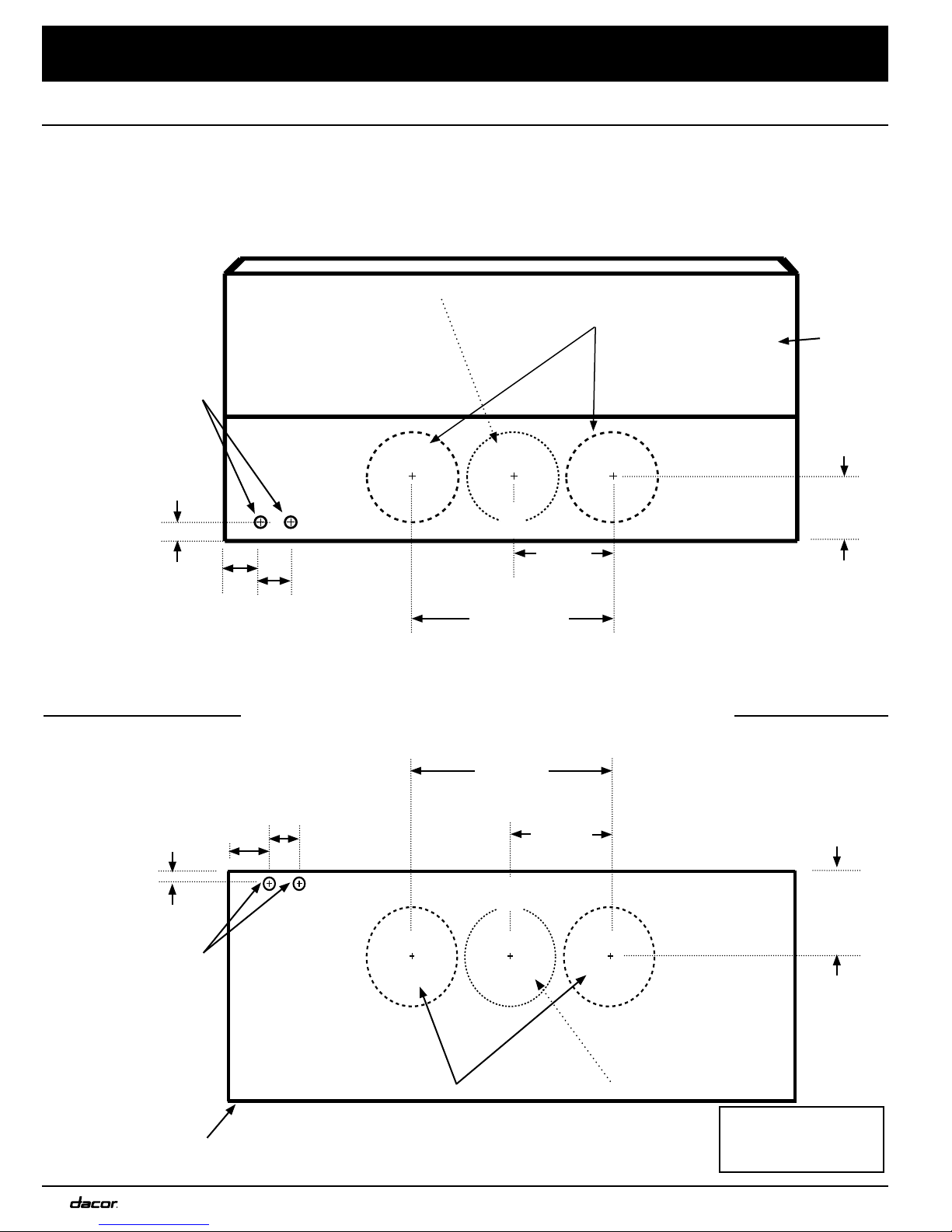
• The minimum vertical distance between the cooktop surface and the exterior part of the hood must be no less
than 30” (76.2 cm). The vertical distance may be longer for the range or cooktop being used. Consult the range or
cooktop Installation Instructions for the minimum and maximum vertical distance from the appliance being used.
• TO REDUCE THE RISK OF FIRE, USE ONLY METAL DUCTWORK.
• PROLONGED POWER FAILURE Do not attempt to use this appliance during a continuous power failure.
WARNING
General Safety Precautions
To reduce the risk of fire, electric shock, serious injury or death when using your appliance, follow basic safety
precautions, including the following:
CAUTION
For general ventilating use only. Do not use to exhaust hazardous or explosive materials and vapors.

3
All Models
Features Description
Fan Speeds Adjustable
Filters Mesh style, dishwasher safe
Exhaust(s) 8-inch duct diameter
Total
Connected
Load
120V, 60 Hz, 9 Amp. Max.
(10.0 Amp Max. surge)
Lights
Halogen 120V, 75W
Size: PAR16 E26/27
(All Replacement Types:
Dimmable with 75W Max)
Individual Models
Model
Number DTHP48 DTHP36 DTHP30
Lights 4 3 2
Filters 4 3 2
Fans 2 1 1
Exhaust
Vents 2 1 1
Fan Rating 1200 CFM 600 CFM 600 CFM
Product Specifications
Model Weight
DTHP3010 51 lbs. (23 kg)
DTHP3018
DTHP3610 53 lbs. (24 kg)
DTHP3618 57 lbs. (26 kg)
DTHP4810 70 lbs. (32 kg)
DTHP4818 77 lbs. (35 kg)
Model
Number Top Vent Rear Vent Rotatable
Fan
DTHP3010 x
DTHP3018 x x x
DTHP3610 x
DTHP3618 x x x
DTHP4810 x
DTHP4818 x x x
General Specifications
Individual Models
Individual Models

4
Dimensions
Product Specifications
Models DTHP48
Models DTHP36 &
DTHP30
*
**
Electrical and Ductwork Connections Tolerances: +1/16” -0”, unless otherwise stated.
Top Connections: All Models
Dual Exhaust Models*
Standard 8-inch duct Back of
hood
9 7/8 in
(25.1 cm)
5 3/4 in
(14.61 cm)
Single Exhaust Models**
Standard 8-inch duct
Electrical access holes
7/8 in dia. (5.1 cm)
C
A
Dual Exhaust Models*
Standard 8-inch duct
Single Exhaust Models**
Standard 8-inch duct
Bottom of
hood
C
Electrical access holes
7/8 in (5.1 cm) (diameter)
19 3/4 in
(50.2 cm)
Connect electrical wires and ductwork through the top or rear of the hood.
5 3/4”
9 7/8 in
(25.1 cm)
A
B
B
(14.61 cm)
See Top Access Holes table on
right page.
See Rear Access Holes table on
right page.
19 3/4 in
(50.2 cm)
C
L
C
L
Rear Connections: DTHP3018, 3618, 4818

5
Product Specifications
Dimensions Tolerances: +1/16” -0” unless otherwise stated.
Single Fan: DTHP30 & DTHP36 Series Dual Fan: Model DTHP48 Series
Model A B C D
DTHP3010 29 7/8” (75.9 cm) 24”
(61 cm)
10”
(25.4 cm)
11 7/8”
(30.2 cm)
DTHP3610 35 7/8” (91.1 cm)
DTHP4810 47 7/8” (121.6 cm)
DTHP3018 29 7/8” (75.9 cm) 24”
(61 cm)
18”
(45.7 cm)
11 7/8”
(30.2 cm)
DTHP3618 35 7/8” (91.1 cm)
DTHP4818 47 7/8” (121.6 cm)
Top Access Holes A B C
DTHP48 1 1/2” (3.81 cm) 5” (12.7 cm) 3” (7.62 cm)
DTHP36 1 1/2” (3.81 cm) 4 1/2” (11.43 cm) 3” (7.62 cm)
DTHP30 1 1/2” (3.81 cm) 5 1/2” (13.97 cm) 3” (7.62 cm)
Rear Access Holes A B C
DTHP48 1” (2.54 cm) 5” (12.7 cm) 3” (7.62 cm)
DTHP36 1” (2.54 cm) 4 1/2” (11.43 cm) 3” (7.62 cm)
DTHP30 1” (2.54 cm) 5 1/2” (13.97 cm) 3” (7.62 cm)
Page 4: Electical Access Dimensions
Hood Dimensions
C
A
D
B
DA
C
B

6
Preparation and Setup
Parts List
B
A
D
C
B
E
C
F
G
G
I
F
STAINLESS
STEEL
CLEANER
D
I
A
E
Hood Installation
Phillips screwdriver Drill + bits Jigsaw
Flathead
screwdriver Tape measure 8” Ducting
Pencil or
marking tool Stud finder Foil tape
Wire connector caps Level Sheet metal
screws
Wire stripper Junction box
18 AWG Wire
or 3-prong
power cord
Necessary Tools and Hardware
Please make sure these tools and hardware are within
reach before beginning the installation.
pictures vary by model
Blower Rotation (optional)
Phillips screwdriver 5/16” Nut driver
Hood Model DTHP48 DTHP36 DTHP30
Mesh
Filters 4 3 2
Halogen
Lights 4 3 2
Hood (1)
Grease channel (1)
Mesh filter
Holding brackets and hardware (2)
Halogen light bulbs
Light replacement tool (1)
Literature (2)
Dacor Cleaning Creme (1)
Dual to Single Vent
Transition Kit (optional accessory)
Dacor Kit #AHT10 Drill Foil tape
10” Ducts and
ducting materials
Sheet metal
screws
E
C

7
Preparation and Setup
Installing the Electrical Source
WARNING
Make sure electrical service to the range hood is installed by a licensed electrician.
It is the owner’s responsibility to confirm that all electrical
requirements are met by a qualified electrician who is is
servicing this appliance.
The electrical installation, including the minimum supply-
wire size and grounding, must be in accordance with the
National Electric code ANSI/NFPA* (or latest revision), local
codes, and ordinances.
*A copy of this standard can be obtained from:
National Fire Protection Association
1 Batterymarch Park
Quincy, Massachusetts 02269-9101
• The ground terminal on the hood must be connected
to a grounded, metallic, permanent wiring system, or a
grounding conductor installed by a licensed electrician.
• Do not ground the appliance or appliance wiring to a
gas pipeline or to the neutral (white) power supply wire.
• Do not install a fuse in the neutral or ground circuit.
• Connect the hood directly to an electrical junction
box. Hard-wire the hood according to local code direct-
ly to a dedicated three-wire grounded, single phase
circuit rated at 120 Vac 60 Hz, 15 Amp.
• See the diagram below: Top or Rear Electrical
Access Holes for wire hole locations inside the hood.
• See Wiring Diagrams at the end of this document.
Hood
Install an electrical junction box near the hood’s electrical
access holes according to local codes.
See image below: Suggested Area of Junction Box.
1. Drill 7/8” holes in the wall or cabinet (as needed) to act
as a passageway for the electrical wiring.
2. See the last pages of this Installation Guide for wire
diagrams.
Meeting Electrical Codes
Junction Box
Area
Suggested Area of Junction BoxTop or Rear Electrical Access Holes
Rear Access
Top Access

8
WARNING
To reduce the risk of personal injury caused by reaching
over a hot appliance, cabinet storage space located
directly above the range should be avoided.
WARNING
Observe all governing codes and ordinances during
planning and installation. Contact your local building
department for further information. Use only ductwork
deemed acceptable by state, municipal and local codes.
IMPORTANT
See the diagram for minimum installed distance from
the hood to the cooktop surface. The minimum specified
distance may be higher for the particular range or
cooktop in use. Check the manufacturers specifications
for the cooktop or range.
E
30” min.*
(76.2 cm)
Electrical
access
* From cooking surface
top
rear
E
Minimum Width of E:
Upper Cabinet Cutout & Appliance Width
Models E
DTHP3010, DTHP3018 30 inches (76.2 cm)
DTHP3610, DTHP3618 36 inches (91.5 cm)
DTHP4810, DTHP4818 48 inches (121.9 cm)
All tolerances: +1/16” -0”, unless otherwise stated.
Preparation and Setup
• The hood must be as wide as the cooktop surface or
wider.
• Plan the installation so that all minimum dimensions
are met or exceeded.
• Dimensions given are minimum clearances, unless oth-
erwise noted.
• All contact surfaces between the hood and any cabine-
try or walls must be sturdy, solid, and at right angles.
• Install the hood and cooking appliance(s) so that they
can be removed if service is required. Cabinet Layout Dimensions
Meeting Installation Requirements

9
Preparation and Setup
The fan factory default direction is through top A of the
hood. However, the fan can be rotated to vent through the
rear B of the hood.
When planning new ductwork, always find the shortest,
most direct route to the outside.
Duct Length Calculation Table
The maximum straight duct length for the hood is deter-
mined by the type of duct used. See the chart below.
Duct Size Maximum Duct Run
8-inch Round 60 feet
10-inch Round 50 feet
3 1/4-in x 10-in Rectangular 50 feet
For each elbow and transition added, a certain length must
be subtracted from the maximum duct run to compensate
for wind resistance.
To determine your maximum length:
1. Start with the total max. length of your duct run, then
2. Subtract all of the ductwork equivalent lengths (see
chart below).
Ductwork Equivalent Lengths
Piece Subtract Piece Subtract
8-inch
90° Elbow 7 feet 10-inch 90° Elbow 5 feet
8-inch
45° Elbow 3 feet 10-inch 45° Elbow 2 feet
3-in x 10-inch
to Round 90°
Transition
25 feet
3¼ in x 10 in to 8
in / 10 in Round
Transition
4 feet
Roof Cap *Wall Cap with
Damper *
* The equivalent lengths of roof and wall caps vary with
model and configuration.
A
B
Planning the Ductwork
WARNING
• To prevent combustion by-products, smoke or odors
from entering the home and to improve efficiency, tape
all duct joints securely.
• Range hoods may interrupt the proper flow of smoke
and combustion gases from furnaces, gas water heat-
ers, and fireplaces. To avoid drawing lethal gases into
the home, follow the manufacturer’s recommendation
for these devices and consult NFPA and ASHRAE rec-
ommendations.
• Failure to install a remote blower or proper ductwork
may result in a backdraft and/or insufficient venting of
smoke and fumes.
• DO NOT install an additional in-line or external blower
to increase the length of the duct run. Even small dif-
ferences between blower air flow rates can greatly
reduce the air draw by the hood.
CAUTION
To reduce the risk of fire and to properly exhaust air, be
sure to duct air outside the house or building. Do not vent
exhaust air into spaces within walls or ceilings or into
attics, crawl spaces or garages.
• Local building codes may require the use of makeup air
systems with ventilation systems that move air greater
than the specified movement rate (CFM).
The specified rate varies based on locale. Consult a
qualified HVAC specialist when designing the system
for the requirements in your area and to assure optimal
performance.
• All ductwork materials (including screws and foil tape)
must be purchased separately.
• Make sure ductwork does not interfere with floor joists
or wall studs.
• Fasten all joints with sheet metal screws and seal with
certified duct tape or foil tape.
• Two 8-inch exhausts may be merged into one 10-inch
duct using Dacor transition kit AHT10. See page 18
for details.
Vent Direction Options
WARNING
During duct installation, make sure there are no
obstructions that keep the damper flaps on the top of the
hood from opening.

10
Ductwork Tips
Wherever possible, reduce the number of transitions, turns,
and sharp angles. Two staggered 45° angles are better
than one sharp 90° angle.
Keep turns as far away from the hood exhaust as possible,
and keep as much space between any bends as possible.
For best performance: use round duct instead of rectangu-
lar, especially when elbows are required.
If multiple elbows are used, try to keep at least 24 inches of
straight duct between each elbow.
Avoid using “S” or back-to-back adjacent elbows.
In extremely cold weather regions, use thermal breaks, i.e.,
short sections of non-metallic duct, to avoid indoor heat
loss. Locate the break as close as possible to the outside
pass-through point.
Do not use flexible metal duct. Do not use ductwork that is
smaller than what is advised in the tables.
• The hood exhaust connects to an 8-inch round duct.
You can increase the duct size over the duct run if
desired.
• To prevent a backdraft, never decrease the duct size
over the run. If existing ductwork is smaller than 8
inches in diameter, remove it and replace it with 8-inch
ductwork.
• Do not rely on tape alone to seal duct joints. Fasten
all connections with sheet metal screws, and tape all
joints with certified duct tape or foil tape.
• Use sheet metal screws as needed to support the
weight of the ducting.
• To prevent backdrafts, a damper at the duct outlet may
also be required.
Preparation and Setup

11
Preparation and Setup
Preparing the Mounting Location
Holding brackets and hardware are provided to temporarily
hold the hood in place while you permanently fasten the
hood to the wall.
The illustrations below show the purpose of the holding
brackets and the support behind the wall.
1. If mounting the hood to brick or masonry, select
anchors capable of holding the full weight of the hood.
2. Make sure the mounting surface is properly reinforced
to support the full weight of the unit.
• If mounting the unit to drywall or a plastered surface,
install a reinforced mounting block between the studs.
• Attach screws directly to the studs and cabinets if they
align with the mounting holes in the back and top of the
hood.
Support Block
Model Weight
DTHP3010 51 lbs. (23 kg)
DTHP3018
DTHP3610 53 lbs. (24 kg)
DTHP3618 57 lbs. (26 kg)
DTHP4810 70 lbs. (32 kg)
DTHP4818 77 lbs. (35 kg)
Stud
Stud
Support Structures Behind the Wall
WARNING
• The electricity to the range hood should be installed
only by a licensed electrician.
• Observe all governing codes and ordinances during
site preparation and installation. Contact your local
building department for further information.
• Failure to properly anchor the hood to the wall may
result in personal injury due to the unit falling off the
wall.
• To avoid an electric shock hazard and property dam-
age, locate electric wires and water pipes and avoid
drilling or cutting in the vicinity.
• Use the temporary holding brackets only to hold the
hood in place until permanent anchoring is secured.
Holding Brackets
(Enlarged for Detail)
Holding Brackets

12
Rear Exhaust Centerline
Top Exhaust Centerline
These measurements and marks are for centering and
leveling the hood, marking the duct cutouts, and installing
the holding brackets.
The holding brackets temporarily hold the hood while you
mount it permanently into place.
Have a marking tool, tape measure, and level ready.
1. Position the hood in the same orientation as it will be
when installed. (For example, if it is a top vent installa-
tion, set the hood with the vents on top.)
2. Measure the distance from the edge of the hood to the
center of the exhaust port.
3. Transfer that measurement to the wall (for a rear vent),
or overhead (for top vent). Measure the X and Y axis to
find the centerline.
4. Extend the line down 10 inches (25.4 cm).
5. Cut a hole that is 1 inch larger than the duct. Dual
exhaust models require two (2) holes.
Marking the Centerlines
Top Exhaust
Rear Exhaust
DTHP48 Top and Rear
Exhaust Centerline
14 1/8”
(35.88 cm)
Installation Instructions
9 7/8”
(25.08 cm)
C
L
C
L
C
L
48” (121.92 cm)

13
Installing the Holding Brackets
IMPORTANT: Placing the holding brackets above, below, or
off the centerline will cause alignment problems during final
installation.
1. Mark the holding bracket’s horizontal centerline 2 1/8
inches (54 cm) below the top of the hood.
2. Next, mark the holding bracket’s two vertical center-
lines. Refer to the table and image on right.
3. Measure and mark the “F” distance.
4. Lay the bracket against the wall, and align the
screwholes with the horizontal centerline.
• Make sure the anchors and/or screws being used are
strong enough to support the hood.
• Make sure drywall installations are properly
reinforced.
5. Mark the two holes in the bracket.
6. Drill those two holes for screws or anchors.
7. Attach the brackets securely to the wall.
2 1/8”
Bracket
placement
Hood
F F
Holding Bracket Cenerline Distance
Models F
DTHP3010, DTHP3018 10 1/2 in (31.75 cm)
DTHP3610, DTHP3618 7 1/8 in (18.1 cm)
DTHP4810, DTHP4818 17 in (43.18 cm)
Hood
location
Step 4
Marking the Centerlines and Brackets
block
Installation Instructions
C
L
C
L
C
L
Mounting
Bracket
placement
Attaching the Brackets to the Wall

14
The 18-inch hoods have fan(s) that can be rotated so that
the air is vented out the back of the hood.
If the hood will be installed in a top exhaust A configura-
tion your hood is already in the factory default, top exhaust
position.
If the hood will be installed in a rear exhaust B configura-
tion, the fans must be rotated so the exhaust vents through
the rear of the hood and to the outside.
This must be done before hanging the hood.
Top Exhaust
Rear
Exhaust
Rotating the Fan(s) for Rear Exhaust
WARNING
• Do not install the range hood unless the electrical service provided meets the range hood specifications.
• Observe all governing codes and ordinances during installation. Contact your local building department for further
information.
• A qualified technician must complete the installation of this built-in appliance. More than one person is required to
raise the hood into place. The owner is responsible to make sure the hood is properly installed.
Tools and Hardware Needed
5/16” Nut driver Phillips screwdriver
Cable ties
AHT10 Transition Kit
(optional) plus metal
screws and foil tape
10” Ducts and
ducting materials
8” Duct and
ducting materials
Installation Instructions
DTHP Models with Fan Rotation:
3018, 3618, 4818
A
B

15
Various models illustrate these instructions, so the images
presented might not be an exact replication of the hood
being installed.
However, the best illustrations were chosen to help
communicate the intended information.
Instructions:
Disassembling Parts
1. Unhook and remove the grease channel.
2. Place the hood assembly on a large, flat surface.
Take special care not to scratch the hood.
3. Remove the duct collar from the top of the unit.
Save the collar and screws.
Installation Instructions
Removing the Fan(s)
4. Tip the hood up, so that it lays on its back.
You are now facing inside the hood.
5. Find the end of the cable assembly, squeeze the
connector, and unplug it.
Do not pull directly on the cable assembly.
Doing so will damage the contacts and wires; always
pull from the connectors.
7. Unscrew the cable clamp(s) and remove the
hardware that holds the fan and L-bracket.
8. Detach the fan and plate, and place them nearby.
continued...
Step 1
Steps 2-3
Rotating the Fans(s) for Rear Exhaust
Front of Hood
Back of Hood
Duct Collar
Back of Hood
Grease Channel
Steps 4-8
L-Bracket
plate
fan

16
Back of
Hood
Default Orientation:
Top Vent Open
Rear Vent Closed
Top of
Hood
L-Bracket
Installation Instructions
Step 9
Rotating the Fans(s) for Rear Exhaust
9. Unscrew and remove the L-bracket that is in the default
top-venting orientation.
10. Turn and align the L-bracket so the hole is in back of
the hood, allowing a rear-venting configuration.
continued...
Step 10
Orientating the Blower/Vent L-Brackets
Back of
Hood
Top of
Hood
Rotated Blower
Orientation:
Top Vent Closed
Rear Vent Open
Blower/Vent
L-Bracket

17
Installation Instructions
Step 14
Cable I/O port
Back of Hood
Top of Hood
Detail: Location of Cable I/O Port
Rotating the Fan(s) for Rear Exhaust
Orientating the Blower(s)
It is imperative that the fan(s) are installed in the correct
orientation.
To do this, make sure the cable I/O port is against the
back of the hood. Confirm the orientation is correct by
comparing it with the figures on the right.
11. Lay the fan over the exit vent with this specific
placement:
When facing the inside of the hood,
• The cable I/O port must be on the right, and
• The cable I/O port must be against the back of
the hood.
Steps 11-13
Finalizing the Rear Vent Setup
12. Refasten the cable clamps and cable assembly to the
hood.
13. Connect the cable assembly to the I/O port.
14. Attach the duct collars to the back of the hood.
15. Place the hood in a safe, upright position.
Cable Clamp

18
Installation Instructions
Four (4) corners are bent backward 90 degrees.
Using the Dual to Single
Transition Kit# AHT10
On dual exhaust models, the two 8-inch duct exhausts can
be transitioned into one 10-inch duct.
Assemble the Dacor transition kit # AHT10 before hanging
the hood. This transition kit fits over the top or rear ventila-
tion exits.
IMPORTANT:
DTHP3010, 3610, 4810 models
CANNOT vent through the rear ducts.
Bending the Flange for:
• Rear Vent Configuration
On models 3018, 3618, 4818
• Notes: 18” hood height requirement
Bending the Flange for:
• Top Vent Configuration
On models 3010, 3610, 4810
3018, 3618, 4818
32”
(81.3 cm)
13 3/4”
(34.9 cm)
3/4”
(1.9 cm)
9”
(22.9 cm)
2” (5.1 cm)
Four (4) corners are bent backward 90 degrees.
Preparing the AHT10
1. Create a lip around the transition kit by bending the
bottom edges backward at right angles to create a 3/4”
flange around the base.
DTHP3010, 3610, 4810
X
This manual suits for next models
5
Table of contents
Other Dacor Ventilation Hood manuals

Dacor
Dacor IVS1 User manual

Dacor
Dacor ERV3015 User manual

Dacor
Dacor DH3606 User manual

Dacor
Dacor ERV3615 Technical manual

Dacor
Dacor ERV30 Technical manual

Dacor
Dacor PREFERENCE PHW30 User manual

Dacor
Dacor DHD30M700WS Installation instructions

Dacor
Dacor DH3006 User manual

Dacor
Dacor ERV3615 User manual

Dacor
Dacor DHD36M976WM User manual

Dacor
Dacor DHW301 User manual

Dacor
Dacor EHD3018 User manual

Dacor
Dacor DHW301 User manual

Dacor
Dacor ERV36-ER User manual

Dacor
Dacor DHD30M967WM User manual

Dacor
Dacor Ventilation Hoods User manual

Dacor
Dacor Epicure EH3612 User manual

Dacor
Dacor ERV30 User manual

Dacor
Dacor DHD30U990WS/DA User manual

Dacor
Dacor ERV3015 User manual