manuals.online logo
Brands
  1. Home
  2. •
  3. Brands
  4. •
  5. Dacor
  6. •
  7. Ventilation Hood
  8. •
  9. Dacor ERV3015 Technical manual

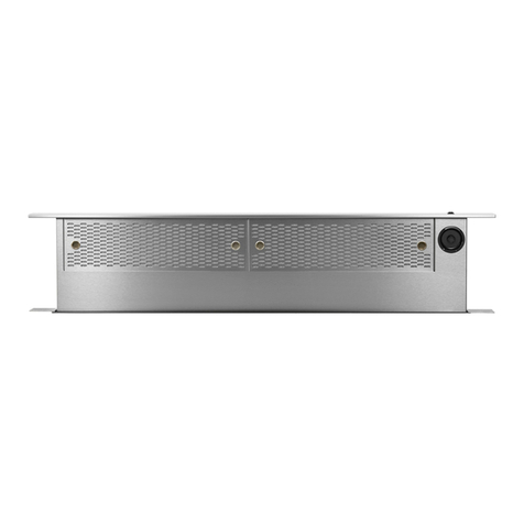
Dacor ERV3015 Technical manual

All specications subject to change without notice. Phone: (800) 793-0093www.dacor.com
PLANNING
GUIDE
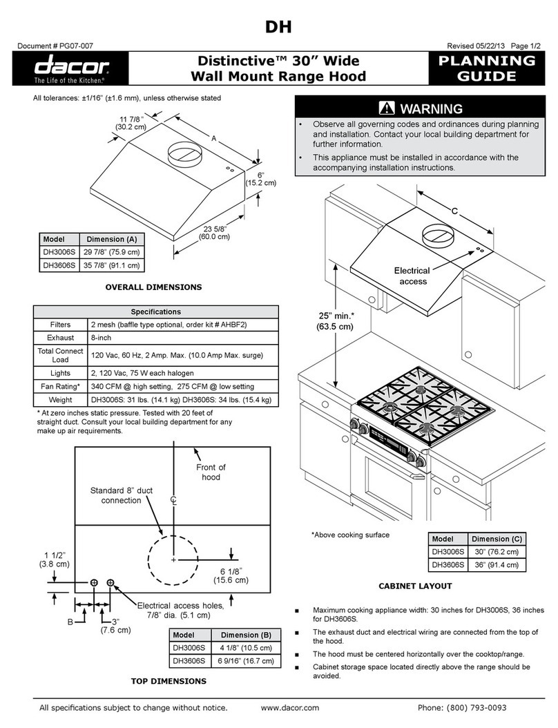
ERV3015, ERV3615
Renaissance® 30”, 36” Wide,
High Extension Slim Raised Vents
Document # PG08-004 Revised 10/28/11 Page 1/3
15"
(38.1 cm)
30"
(76.2 cm)
20”
(50.8 cm)
1 1/8”
(2.9 cm)
28" 3 prong
grounded
power cord
Motor
cover
Front of unit
6”
(15.2 cm)
2 9/16”
(6.5 cm)
9/16”
(1.4 cm)
3”
(7.6 cm)
1 15/16”
(4.9 cm)
B
A
2 1/8”
(5.4 cm)
2 3/16”
(5.6 cm)
3/16”
(5 mm)
5/16” (8 mm)
thick stiffener
across back
Top cap with
vent down
Vent shown
in raised
position
3 3/4”
(9.5 cm)
30 1/4”
(76.8 cm)
to
37 1/4”
(94.6 cm)
Adjustable
anchor legs
Product
data label
DIMENSIONS SIDE VIEW DIMENSIONS FRONT VIEW
All tolerances: ±1/16” (±1.6 mm)
unless otherwise stated
WARNING
• Observe all governing codes and ordinances
during planning and installation. Contact your
local building department for further information.
• This appliance must be installed in accordance
with the accompanying installation instructions.
2 1/8”(5.4 cm)
3/8”
(1.0 cm)
Top cap - side view
Model No. A B Circuit
Requirement**
ERV3015 30”
(76.2 cm)
27 3/8”
(69.5 cm)
Three prong electri-
cal outlet connected
to 120 Vac, 60 Hz.,
15 Amp. grounded,
dedicated, circuit
ERV3615 36”
(91.4 cm)
33 3/8"
84.8 cm)
** Includes power supply requirements for external blower
NOTES:
1. The maximum installed height must not exceed the
maximum specified countertop height of cooking
appliances.
2. Install these raised vents only with approved Dacor
appliances. See the planning guide for the particular
appliance for proper applications and cutout information.
3. This appliance must be install in conjunction with a
single Dacor approved remote or in-line blower. See
following pages for approved blowers.
All specications subject to change without notice. Phone: (800) 793-0093www.dacor.com
PLANNING
GUIDE
EERV3015, ERV3615
Renaissance 30”, 36” Wide,
High Extension Slim Raised Vents
Document # PG08-004 Revised 10/28/11 Page 2/3
Duct Work Design Tips
■Wherever possible, reduce the number of transitions and turns to as
few sharp angles as possible. Two staggered 45° angles are better
than one 90°. Keep turns as far away from the hood exhaust as
possible, with as much space between each bend as possible.
■For best performance, use round duct instead of rectangular when
possible, especially when elbows are required.
■If multiple elbows are used, try to keep a minimum of 24” of straight
duct between them. Avoid “S” or “back to back” configurations of
adjacent elbows.
■Do not use flexible metal duct.
Calculating the Maximum Duct Run Length
■Do not use duct work that is smaller in cross-sectional area than the
required duct sizes in the table to the right.
■For best performance, keep the duct run as short as possible and
never exceed the maximums stated at the right.
■The maximum straight duct length for the raised vent system depends
on the model of remote or in-line blower used with the vent system
and the number of elbows and transitions used. The Equivalent
Number of Feet for each elbow and transition (see table) must be
subtracted from the maximum straight length to compensate for
wind resistance. To determine the maximum allowable length of the
duct work, subtract all of the equivalent lengths of the elbows and
transitions from the Blower Maximum Duct Straight Length.
For example, for a raised vent system using 3 ¼” X 10” rectangular
duct, two (2) 3 ¼” X 10” 90°elbows, a 3 ¼” X 10” rectangular to 10”
round transition, and a REMP16 remote blower:
■From the Blower Maximum Duct Straight Length table, the
maximum length without transitions and elbows is 60 feet.
■The equivalent length of each 90°elbow is 15 feet.
■The equivalent length of 45°elbow is 2 feet.
■The equivalent length of the transition is 4 feet.
■The total equivalent length of the above components is: 15 feet + 15
feet + 4 feet + 2 feet = 36 feet.
■The maximum amount of straight duct that can be used with a
REMP16 and the above components is: 60 feet - 34 feet = 24 feet.
Equivalent Number of Feet -
Duct Elbows and Transitions
45° elbow
8 Inch 3 feet 3 ¼” X 10
45° elbow 7 feet
45° elbow
10 Inch 2 feet 3 ¼” X 10
90° elbow 15 feet
90° elbow
8 Inch 7 feet 3 ¼” X 10
90°atelbow 20 feet
90° elbow
10 Inch” 5 feet
3 ¼” X 10
to 8” round
transition
4 feet
90° 3 ¼” X 10 to 8”
round
transition
25 feet
3 ¼” X 10
to 10” round
transition
4 feet
Roof cap * Wall cap *
* The equivalent lengths of roof and wall caps vary with model and
configuration. For equivalent length, contact the manufacturer or a qualified
HVAC specialist.
Raised Vent
Model No.
Approved Dacor
Blowers*
ERV3015
ERV3615
Remote blowers:
REMP3 or REMP16
In-line blowers:
ILHSF8 or ILHSF10
*For detailed information on the remote/in-line blowers,
refer to the blower installation instructions.
Duct Size
Used
Blower Maximum Duct Straight Length
REMP3 Remote Blower REMP16 Remote Blower ILHSF8 In-line Blower ILHSF10 In-line Blower
8 inch 50 feet (15.2 meters) 60 feet (18.3 meters) 50 feet (15.2 meters) 60 feet (18.3 meters)
10 inch 40 feet (12.2 meters) 70 feet (21.3 meters) 40 feet (12.2 meters) 70 feet (21.3 meters)
3 ¼” X 10” 40 feet (12.2 meters) 60 feet (18.3 meters) 40 feet (12.2 meters) 60 feet (18.3 meters)
All specications subject to change without notice. Phone: (800) 793-0093www.dacor.com
PLANNING
GUIDE
ERV3015, ERV3615
Renaissance 30”, 36” Wide,
High Extension Slim Raised Vents
Document # PG08-004 Revised 10/28/11 Page 3/3
EXHAUST OUTLET LOCATION OPTIONS
FRONT VIEW
SIDE VIEW
All tolerances: ±1/16” (±1.6 mm) unless otherwise stated
NOTE: See the appliance planning guide page for cutout dimensions

Rear Exhaust Knock Out (3 ¼”X 10”)
3”



Vertical center line of rear exhaust knock out lines up with vertical
center line of chassis


The vertical center line of bottom knock out is offset 3”


Side Exhaust Knock Outs (1 ⅝”X 16”)




Bottom Exhaust Knock Out (1 ⅝”X 16”)


Motor
cover
Front of unit
26" (66.0 cm)
6 1/2”
(16.5 cm)
1 1/8”
(2.9 cm)
C
L
C
L
C
L
ADT2 TRANSITION (INCLUDED)
WIRING/CONDUIT CONNECTIONS FOR
REMOTE/IN-LINE BLOWER
3 ¼” X 10” to duct work
2” X 16”, connects to
side or bottom exhaust
on raised vent
1"
(2.5 cm)
5"
(12.7 cm)
Blower wiring access
hole in bottom
Front of unit
Blower wiring
access hole in
side

Other manuals for ERV3015

5

This manual suits for next models

1

Other Dacor Ventilation Hood manuals

Dacor EPICURE EH30 User manual

Dacor

Dacor EPICURE EH30 User manual

Dacor RNHP36 Renaissance User manual

Dacor

Dacor RNHP36 Renaissance User manual

Dacor RV30 Technical manual

Dacor

Dacor RV30 Technical manual

Dacor RV46 User manual

Dacor

Dacor RV46 User manual

Dacor IVS1 User manual

Dacor

Dacor IVS1 User manual

Dacor ERV3615 User manual

Dacor

Dacor ERV3615 User manual

Dacor RNHP3012 User manual

Dacor

Dacor RNHP3012 User manual

Dacor DHW301 User manual

Dacor

Dacor DHW301 User manual

Dacor DH3606 Technical manual

Dacor

Dacor DH3606 Technical manual

Dacor DHI361 Technical manual

Dacor

Dacor DHI361 Technical manual

Dacor RNHP30 Renaissance User manual

Dacor

Dacor RNHP30 Renaissance User manual

Dacor DHD U990W/DA Series User manual

Dacor

Dacor DHD U990W/DA Series User manual

Dacor PHG30 User manual

Dacor

Dacor PHG30 User manual

Dacor PCOR30 User manual

Dacor

Dacor PCOR30 User manual

Dacor Ventilation Hoods User manual

Dacor

Dacor Ventilation Hoods User manual

Dacor DHW301 User manual

Dacor

Dacor DHW301 User manual

Dacor DH3606 User manual

Dacor

Dacor DH3606 User manual

Dacor DHW301 Technical manual

Dacor

Dacor DHW301 Technical manual

Dacor Epicure EHD3018 User manual

Dacor

Dacor Epicure EHD3018 User manual

Dacor ERV3015 User manual

Dacor

Dacor ERV3015 User manual

Dacor DHD U990C Series Installation instructions

Dacor

Dacor DHD U990C Series Installation instructions

Dacor DHD30 Series User manual

Dacor

Dacor DHD30 Series User manual

Dacor DHD-D0000CS/DA User manual

Dacor

Dacor DHD-D0000CS/DA User manual

Dacor HWHE30 User manual

Dacor

Dacor HWHE30 User manual

Popular Ventilation Hood manuals by other brands

Bosch DFO060W50 instruction manual

Bosch

Bosch DFO060W50 instruction manual

Broan BUEZ0 installation instructions

Broan

Broan BUEZ0 installation instructions

Bosch DFT63CA.1 Series instruction manual

Bosch

Bosch DFT63CA.1 Series instruction manual

Inalto ASL60DR2S user manual

Inalto

Inalto ASL60DR2S user manual

AEG Perfekt Visor?24 instruction manual

AEG

AEG Perfekt Visor?24 instruction manual

Kuppersbusch DW9500.0 Instructions for use

Kuppersbusch

Kuppersbusch DW9500.0 Instructions for use

Amica OKP8655S operating instructions

Amica

Amica OKP8655S operating instructions

XtremeAIR UL14- U30 Installation guide & user manual

XtremeAIR

XtremeAIR UL14- U30 Installation guide & user manual

AEG DI 8610 Operating and installation instructions

AEG

AEG DI 8610 Operating and installation instructions

Primada PRH900 instruction manual

Primada

Primada PRH900 instruction manual

Faber HILTIS36WHNB installation instructions

Faber

Faber HILTIS36WHNB installation instructions

Hotpoint HXB9.8LT operating instructions

Hotpoint

Hotpoint HXB9.8LT operating instructions

Guzzanti GZ-443W user manual

Guzzanti

Guzzanti GZ-443W user manual

Windster RA-60TB30SS user manual

Windster

Windster RA-60TB30SS user manual

Sirius Satellite Radio SU-DD2-L TC Installation, Use and Maintenance Instruction

Sirius Satellite Radio

Sirius Satellite Radio SU-DD2-L TC Installation, Use and Maintenance Instruction

ZUG DWQS 6 operating instructions

ZUG

ZUG DWQS 6 operating instructions

Wolf PRO VENTILATION HOODSeries Use and care guide

Wolf

Wolf PRO VENTILATION HOODSeries Use and care guide

Miele DA 6590 W Installation diagram

Miele

Miele DA 6590 W Installation diagram

manuals.online logo
manuals.online logoBrands
  • About & Mission
  • Contact us
  • Privacy Policy
  • Terms and Conditions

Copyright 2025 Manuals.Online. All Rights Reserved.