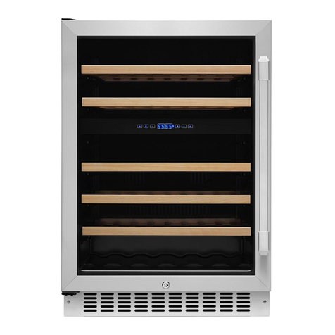
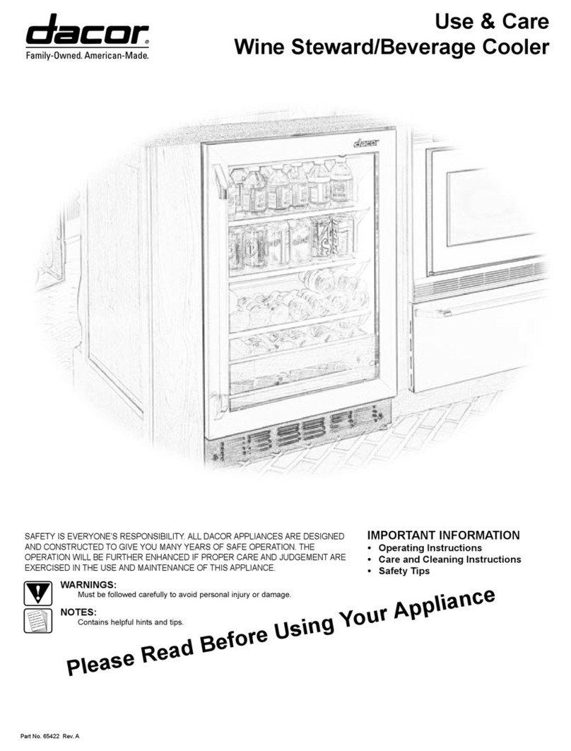
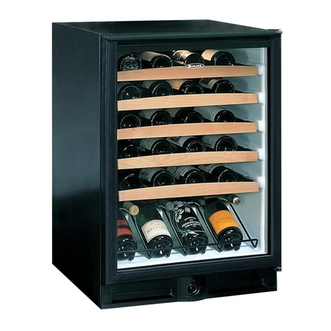
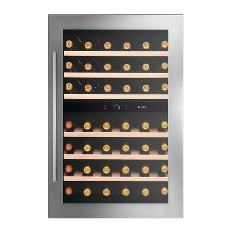
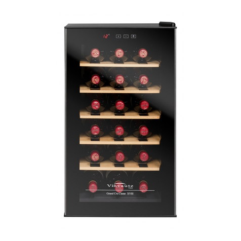
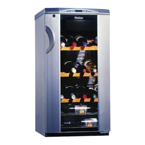
Dacor Wine Steward/Beverage Cooler User manual

IMPORTANT
1. Before beginning installation, please thoroughly read and become familiar with these instructions.
2. Installation and service must be completed by a qualified installer or service agency.
3. Installer: Please leave these Installation Instructions with the owner.
4. Owner: Please keep these instructions for local electrical inspector’s use and for future reference.
5. Read the accompanying Use & Care Manual prior to operating this appliance.
TABLE OF CONTENTS
Verifying package contents Page 2
Installation planning Page 2
Overall dimensions Pages 2
Cabinet preparation Page 3
Electrical power supply requirements Page 3
Staining wood drawer fronts Page 4
Reverse door swing Page 4
Applying Dacor Nameplate Page 4
Installing Toekick Page 4
Leveling Page 5
Connecting to Electric Power Page 5
Slide into Cutout Page 5
Verifying proper operation Page 5
Part No. 65423 Rev. A
TESTED IN ACCORDANCE WITH THE LATEST EDITION OF ANSI/UL 858-2001 AND CAN/CSA-C22.2 NO. 64
STANDARD FOR HOUSEHOLD ELECTRIC COOKING AND LIQUID HEATING APPLIANCES.
NOTES:
Contain helpful hints and tips to facilitate the installation.
CONVENTIONS USED IN THESE INSTRUCTIONS
WARNINGS:
Must be followed carefully to avoid personal injury or damage.
SAVE AND READ THESE INSTRUCTIONS
Installation Instructions
Wine Steward/Beverage Cooler

1
WARNINGS:
1. Read all instructions before
using the appliance.
2. This appliance must be
grounded. Connect only to a
properly grounded outlet. See
“Grounding Instructions”.
3. Install or locate this appliance
only in accordance with these
installation instructions.
4. Use this appliance only for
its intended use as described
in this manual. Do not use
corrosive chemicals or vapors
in this appliance.
5. As with any appliance, close
supervision is necessary
when used by children.
6. Do not operate this appliance
if it has a damaged electrical
cord or plug, if it is not
working properly or if it has
been damaged or dropped.
7. This appliance should be
serviced only by qualified
service personnel. Contact the
nearest DACOR Authorized
Servicer at (800) 772-7778,
or at www.dacor.com for
examination, repair or
adjustment.
8. Do not cover or block any
openings on the appliance.
9. Do not store or use this
appliance outdoors, execpt
as noted below. Do not use
this product near water – for
example, near a kitchen sink,
in a wet basement or near a
swimming pool, etc.
10. Do not immerse the electrical
cord or plug in water.
11. Keep the electrical cord away
from heated surfaces.
IMPORTANT SAFETY INSTRUCTIONS

2
NOTE:
All dimensional tolerances are
+ 1/16”, - 0” unless otherwise
stated. (Metric dimensions are for
reference only.)
Verifying the Package Contents
• Use and Care manual
• Dacor nameplate
• Hardware for changing door swing
• Left and right side hinge covers
• Top screw hole cover
Installation Planning
A qualified technician must complete the
installation of this built-in appliance. Proper
installation is your responsibility.
Carefully check the location where the appliance
is to be installed. The appliance should be
placed for convenient access. Make certain that
electrical power can be provided in the selected
location.
Plan the installation so that all minimum
clearances are met or exceeded. Dimensions
shown provide minimum clearances, unless
otherwise noted. Be certain that proper
clearance is provided for the appliance door
when it is in the open position.
The specified minimum cabinet depth and width
must be provided.
Cabinet cutout dimensions must be used as
indicated. All contact surfaces between the
appliance and the cabinet must be solid and
level.
Make certain that you have everything
necessary to ensure a proper installation before
proceeding.
Overall Dimensions
(EWC, EBC)
Product Clearances
The wine chiller, wine reserve and beverage
center is factory set for a 110° door swing.
When installed in a corner:
• Allow 4” min. clearance on the hinge
side for the 90° door swing and to
allow racks to slide out.
• Allow 10” minimum clearance on the
hinge side for a full 110° door swing.
21 5/8”
(651mm)
23 5/8”
(600mm)
4“ Minimum to Wall
(102mm)
90°
10” Minimum to Wall
(254mm)
110°
Choose the location:
• These products may be closed in on
the top and three sides as long as the
front is unobstructed for air circulation
and proper access to the door.
• Do not install these products where
the temperature will go below 55°F
(13°C) or above 90°F (32°C).
• Do not install where it will be subject
to direct sunlight, heat or moisture.
23 3/4”
(603mm)
34 1/2” - 35”
(876mm - 597mm)
23 3/4”
(603mm)
• The door swing is reversible on all
models. If desired, change the door
swing before installation.

3
Cabinet Preparation
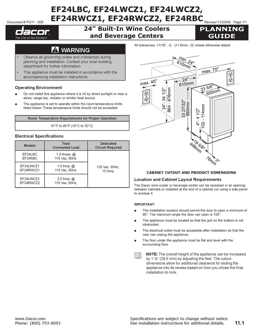
The cutout depth should be 24″
The cutout dimensions shown allow for a full door swing and access to the pull-out racks when
installed as a built-in in standard 24″ deep cabinets.
• The wine chiller, wine reserve and beverage center can be installed freestanding.
• If installing between frameless cabinets, a 1/2″ wide filler strip or side panel may be
needed on hinge side. The filler strip will act as a spacer between the case and adjacent
cabinet door swing.The width of the opening must include the filler panels.
NOTE:
The front face of the chassis should be even with the adjacent cabinetry.
SIDE-BY-SIDE INSTALLATIONS
Increase storage capacity by installing two beverage centers or wine chillers together.
• A side-by-side installation requires at least a 47-1/2″ wide opening. No trim kits required.
• Products must operate from separate, properly grounded receptacles.
STACKED INSTALLATIONS
Increase storage capacity by installing two beverage centers or wine chillers together.
• A stacked installation requires at least a 23 3/4” wide opening. No trim kits required.
• A cutout height of 34 1/2” - 35” is required.
• A minimum of 2” rail is required between units.
• A 3/4” or better support platform must be provided for the upper unit.
• Products must operate from separate, properly grounded, receptacles.
Electrical Power Supply
Requirements
NOTES:
1. If the power supply
requirements shown do
not agree with those listed
on the product data plate,
provide a power source per
the information found on the
product data plate.
2. If the electrical service
provided does not meet the
product specification, or
does not conform to the NEC
or local standards, do not
proceed with the installation.
Call a licensed electrician to
correct the electrical service
before proceeding.
3. Be certain to locate the
electrical receptacle in an
accessible location, so that
the appliance may be easily
unplugged in the event that
service becomes necessary.
4. Do not use an extension cord
to connect the appliance to the
electrical receptacle.
5. It is the owner’s responsibility
to ensure that electrical
installation of this appliance is
performed by a qualified
electrician. The electrical
installation must comply
with the National Electric
Code ANSI/NFPA 70-1990 (or
to latest revision) and local
codes and ordinances.
6. GFI (ground fault interrupter)
is not recommended
Electrical Supply Requirements
120VAC, 60 Hz, 15A Dedicated Circuit
Appliance is supplied with a 48” (1219mm)
power cord with a three prong grounded
plug.
Total Connected Load .01kW (1.2A)
Locate
Outlet
10 1/2”
(267mm)
9“ Max.
(229mm)
24”
(610mm)
34 1/2” - 35”
(876mm - 889mm)
1 1/2”
(38mm)
23 3/4” Min.
(603mm)
Locate Outlet
24”
(610mm)
1 1/2”
(38mm)
47 1/2” Min.
(1207mm)
15”
(381mm)
10 1/2”
(267mm)
10 1/2”
(267mm)
9“
(227mm)
34 1/2” - 35”
(876mm - 889mm)

4
Staining Wood Drawer Fronts
The drawer fronts are unfinished maple wood.
During use, oil from hands may accumulate and
stain the wood.
• The drawer fronts may be stained and
sealed to match adjacent cabinetry.
The tinted glass will make the stained
wood appear darker. A true color
match can be seen only when the
door is opened.
• Apply the stain and sealer according
to the manufacturer’s instructions. To
avoid unpleasant odor, keep the door
open to ventilate and allow
the stain/sealer to dry completely
before using
Reverse Door Swing
NOTE:
Skip this step if door swing suits
the installation.
Parts Included:
• Top left case hinge
• Bottom left case hinge
• Left and right side decorative hinge
cover
• Decorative hinge screw hole cover
• Torx® driver bit
Tools Required:
• Phillips screwdriver
• Electric drill
Remove the door:
• Flatten the shipping carton to use as a
pad.
• Remove the 2 screws and the toekick.
Set aside the screws and toekick for
final installation.
• Use the supplied Torx® bit and
electric drill to remove the 3 screws
holding the top case hinge. Lift off the
hinge. (Screws will be used to install
the new hinge.)
• Lift the door off the bottom case
hinge.
• Remove the bottom case hinge pin
and bracket.
Rotate the door:
• The handle will be on the right side of
the door; hinges will be installed on
the left side of the case.
• Remove the door stop and cam riser
on the original bottom right side of the
door.
• Remove the fill plug on the top right
side of the door.
• Turn the door over and reinstall the fill
plug on the new left side.
Reinstall the door:
• Install the original door stop and cam
riser onto the bottom left side of the
door.
• Install the new supplied bottom case
hinge pin and bracket onto bottom left
side.
• Place the door onto the bottom case
hinge.
• Install the supplied left-hand top case
hinge with the 3 original screws.
• Select the hinge cover marked with an
“L”.
• Peel backing off the tape inside the
decorative hinge cover.
• Press and snap the hinge
cover into place.
• Snap the screw hole cover into place
on the opposite side.
NOTE:
Check to be sure screws are tight
and that the door is straight and
does not sag. The door should
swing freely.
Install Covers
Install
3 Hinge
Screws
Remove
Top Hinge
Remove
Hinge
Hinge
Pin and Bracket
Door Stop
and Cam Riser
Applying Dacor Nameplate
Follow instructions on the back page for
installation of the Dacor nameplate.
Install Toekick
The toekick has a cutout on the left and right
sides. Remove the plug on the left side and
reinstall on the right side.
• Install original screws and spacers.
Install screws through the spacer
standoff, toekick and into the base as
shown.
Move Fill
Plug to
Right Side

5
Verifying the Operation
Connect power to the electrical receptacle.
Operate the appliance as outlined in the Use &
Care Manual, that accompanied this product.
Connecting the Electrical Power
WARNINGS:
1. Verify that the proper electrical
power supply has been
provided.
2. Verify that the electrical supply
matches the ratings found on
the appliance data plate before
proceeding.
3. Be certain that power to the
electrical receptacle has been
disconnected, then plug the
appliance into the electrical
receptacle.
4. This appliance must be
connected to a grounded,
metallic, permanent wiring
system. Alternatively, a
grounding conductor should
be connected to the grounding
terminal or lead on the
appliance. Failure to do so
may result in an electrical
shock hazard.
Three-Prong Plug
Three-prong grounded receptacle
and cover plate
Grounding Instructions
The appliance is supplied with a four (4) foot
long power cord terminated by a three-prong
plug. The appliance power cord is intended to be
plugged directly into a wall-mounted electrical
receptacle. The correct voltage, frequency and
amperage must be supplied to the electrical
receptacle from a grounded, single phase circuit
that is protected by a properly sized circuit
breaker or time-delay fuse. The required voltage,
frequency and amperage ratings are listed on the
product data plate (located on the bottom of the
chassis on the left side).
Slide Product Into the Cutout
• Carefully, slide the unit into the
opening. Be careful not to entangle
power cord.
• Make certain that the chassis is even
with the adjacent cabinetry.
• Check again to be sure the unit is
level.
Leveling
• Use an adjustable wrench to turn the
leveling legs and raise or lower the
product.
• Adjust carefully; the product should
be level and plumb with cabinetry,
and should align with adjacent
toekick height.
Turn Right to Lower
Turn Left to Raise
If you did not reverse the door swing:
• Select the hinge cover marked “R” or
“L”, depending on door swing.
• Peel backing off the tape inside the
decorative hinge cover. Press and
snap into position.
• Snap the screw hole cover into place
on the opposite side.
5. Do not use an extension cord
with this appliance. Such use
may result in fire, electrical
shock, or other personal
injury.
6. Do not install a fuse in the
neutral or ground circuit. A
fuse in the neutral or ground
circuit may result in an
electrical shock hazard.
6
NOTES:

Web Site: www.dacor.com
For a Dealer/Service: (800) 772-7778
Corporate Phone: (800) 793-0093
TEMPLATE FOR NAMEPLATE LOCATION
To position nameplate:
• Cut template along dotted line.
• Tape template on the stainless steel trim above
the glass on the opposite side of the door handle.
Align the bottom edge of the template with bottom
of the trim and side of the template with the vertical
seam on the trim (see illustration). If the door has
been reversed, reverse the template for nameplate
alignment.
DOOR NAMEPLATE TEMPLATE
• Remove backing from nameplate.
• Place nameplate onto the front side of the door, so
that the bottom of the nameplate is level with the
top of the template.
IMPORTANT: Nameplate must be placed on the opposite side
of the door handle.
DOOR NAMEPLATE TEMPLATE
Other manuals for Wine Steward/Beverage Cooler
1
Table of contents
Other Dacor Wine Cooler manuals

Dacor
Dacor DRW24980RAP/LAP User manual

Dacor
Dacor RNF242WCL Installation guide

Dacor
Dacor EF24LWCZ1SS Technical manual

Dacor
Dacor EF24LWCZ2SS User manual

Dacor
Dacor HWC241 Series User manual

Dacor
Dacor EF24LWCZ1SS User manual

Dacor
Dacor Discovery DYWS4 User manual

Dacor
Dacor RNF241WCL Installation guide

Dacor
Dacor HWC242L User manual

Dacor
Dacor EF24RBCSS Owner's manual