manuals.online logo
Brands
  1. Home
  2. •
  3. Brands
  4. •
  5. DAEHAN
  6. •
  7. Lighting Equipment
  8. •
  9. DAEHAN STAR L02 User manual

DAEHAN STAR L02 User manual

User Guide STAR L02 1
PHYSICAL
ELECTRICAL
Current dissipation : 60 mA
Power Consumption : 0,72 W
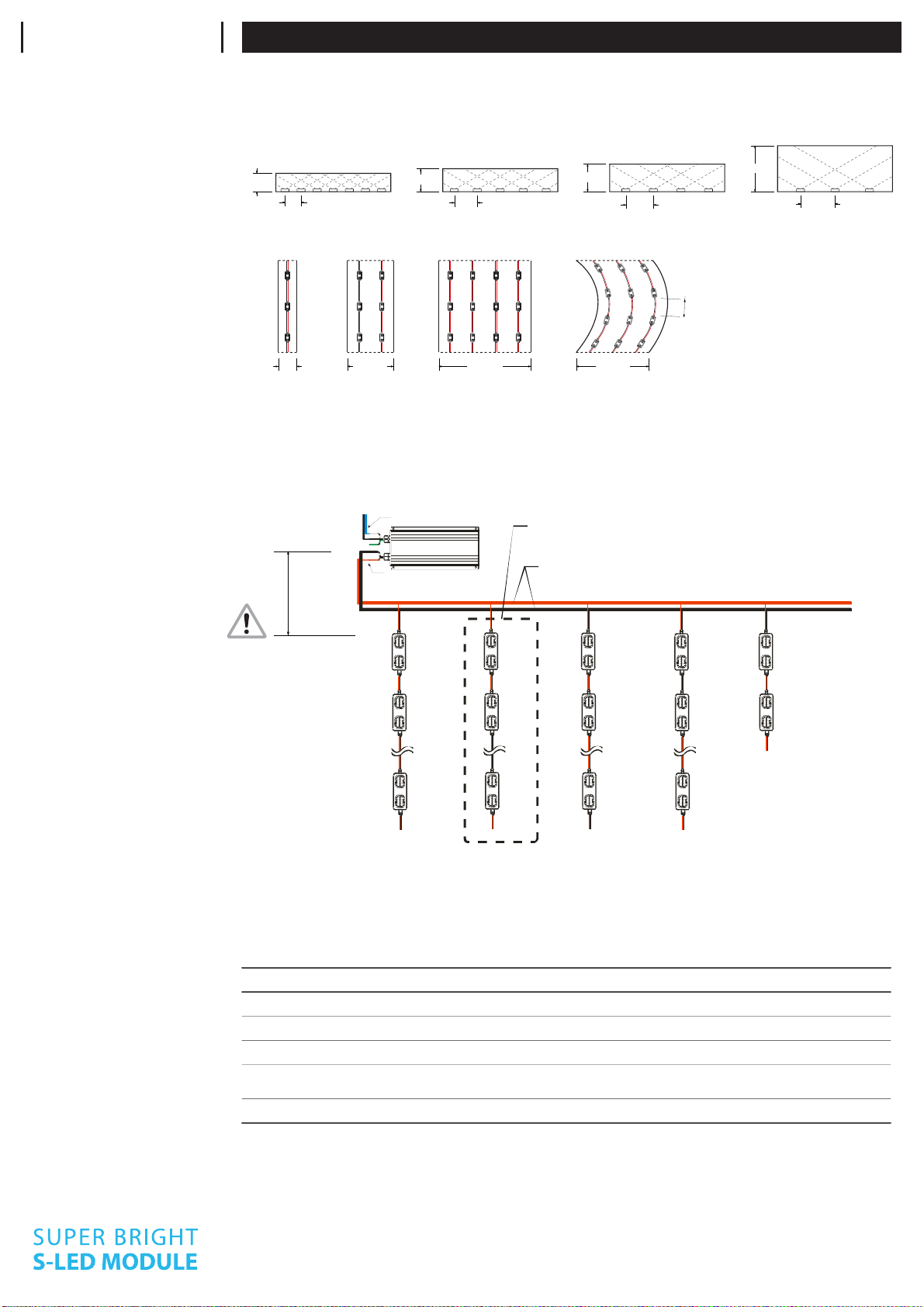
Operating power : DC 12V
Maximum serial connection : 50 modules
Electronic dimming control supported
THERMAL
Cooling : Ambient air
Maximum operating temperature : 60˚C
Minimum operating temperature : -25˚C
Maximum storage temperature : 60˚C
Minimum storage temperature : -30 C
SPECIFICATIONS
Use precautions to avoid damages to the product or injuries of users. Any actions against following contents will cause serious
issues such as malfunction, electric shock, or burn.
USE DC12V ONLY
DC12V
DO NOT USE AC INPUT
AC
INPUT
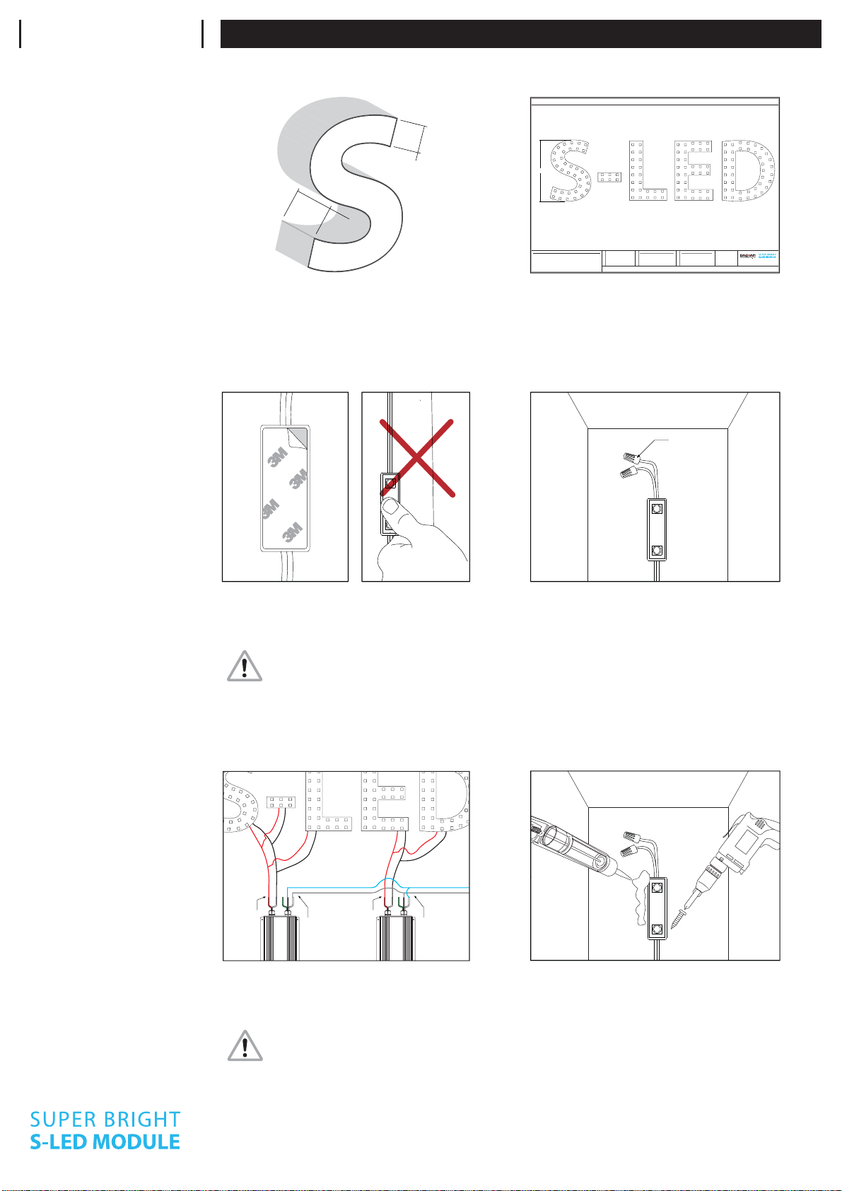
Do not cut or rejoion wires while product
is connected wth live power source
Maximum driver quantity per serial
connection is limited. Failure causes overload
of current and damages to the product
Refer to‘WIRE THICKNESS’table to use proper
wire thickness between SMPS and the first
LED module
Failure will cause dimmed output
Cable length between SMPS and the first LED
module is limited. Refer to ‘CONNECTION
WITH POWER SUPPLY’ on page 2
Do not use the product under circumstances
listed below
- High temperature spots over 60˚C (140˚F)
- Spots draw extreme moisture or dust
- Spots have corrosive gas or highly eectied
by electromagnetic field
Avoid performing installation under rain or
high humidity for outdoor use
Do not perform actions listed below
- Alter or modify
- Touch LED lamps with sharp objects
- Put glue or silicon over the LED lamps
PRECAUTIONS
PREPARATION
PREPARE CHANNELS
1. Clean moisture and dust inside 2. Make holes 3. Use bushing to protect wires
1. Wipe out dust, water, and oil inside. 3M tape will come o easily if product is mounted on uncleaned surfaces.
2. Make holes for wires from modules to SMPS.
3. Without bushins, wires will easily be cut and short-circuit will occur.
*Use white paint inside the channels for better reflection
SUPPLIES REQUIREDTOOLS REQUIRED
Wire Nuts, Cable Ties, IDC Connectors, VCTF(PLTC) Cable,
(Optional : Silicon and Screws)
Wire Stripper, Drill, Screw Driver, Wiper
IP65
Nonpolar
Input Connection
FARD lighting GmbH Seestrasse 20 D - 14974 Ludwigsfelde OT Genshagen
Tel. +49 - (0)3378 / 2003-0 Fax +49 - (0)3378 / 2003-29
[email protected] www.fard-lighting.de
User Guide STAR L02 2
Maximum driver quantity per serial connection is limited. Using more quantity per run will cause overload from SMPS which
damages all connected products. This will cause voltage drop and also dimmed lighting output.
CAUTION
Keep extension lead
wires as short as possible.
Refer to below table for
specific length.
CONNECTION GUIDE
Use recommended length for pitch between each module to achieve optimum lighting output while maintaining lowest unit
cost. Failure or misplacing will cause dimmed spots or uneven appearance of light on the surface.
LAYOUT DENSITY
GUIDELINES
RECOMMENDED PITCH PER DEPTH
140 mm
70 mm
100 mm
140 mm
55 mm
100 mm
70 mm
40 mm
RECOMMENDED LAYOUT DENSITY PER CHANNEL WIDTH
80 mm 200 mm 400 mm 316 mm
Use 10% shorter length
than usual for circular arrange
CONNECTION WITH
POWER SUPPLY
Output (W)
Model Name
Recommended
Extension Wire
Output (A)
Max Q’TY
Maximum Length
30W
2.5A
PSCV03012
5M (15FT)
VCTF1.25
AWG18
60W
5A
PSCV06012
5M (15FT)
VCTF2.0
AWG14
120W
10A
PSCV12012
5M (15FT)
VCTF2.0
AWG12
300W
25A
PSCV30012**
15M (50FT)
VCTF5.5
AWG4
600W
50A
PSCV60012**
15M (50FT)
VCTF8.0
AWG2
EXTENSION OF POWER SUPPLY LEAD WIRES
*Maximum quantity for S-LED is based on 85% of specified capacity of power supplies for extended lifespan
**PSCV30012, PSCV60012 are not weather-proof
Equip with protective box for outdoor use and the box should have ventilating holes
32pcs 64pcs 128pcs 320pcs 640pcs
FARD lighting GmbH Seestrasse 20 D - 14974 Ludwigsfelde OT Genshagen
Tel. +49 - (0)3378 / 2003-0 Fax +49 - (0)3378 / 2003-29
[email protected] www.fard-lighting.de
Power Supply
AC Input
DC Output
Make sure that each run should have 50 modules at max
and should use another run in parallel to connect more
Should use thicker wires which can take larger amount of current
than the amount transmitted from the power supply unit
1st
2nd
50th
1st
2nd
1st
2nd
50th
1st
2nd
50th
1st
2nd
50th
User Guide STAR L02 3
INSTALLATION GUIDE
Drawn by Brad Han
Date : 2009. 1. 1.
Rev.0 Tel: +82 32 858 0491
www.daehantrans.com
Fax: +82 32 832 8421
[email protected]
MATERIAL ESTIMATE
Attention to : John Doe Page 1 of 1
NUMBEROF SETInformation ytitnauQylppuSrewoPledoM Color Quantity
2W021V21CDAE341ETIHW40CRATS
S-LEDESTIMATE /SET
SUMMARY
POWERESTIMATE /SET
MODULEPITCH
1
QUANTITYPER SET 143EA
TOTALCLUSTERS 143EA
WATTAGEPER SET 187W
TOTALWATTAGE 187W
120mm
*Thisis for estimating purposes only. Material Estimates for S-LED system are based upon given font, letter height, depth, facematerial, and any special instructions. *Missinginformation will aect the final results *Powerconsumptionis calculated with extra 15% for extended life of power supplies
*Allsigns should be tested for acceptable color, illumination and operation. Use appropriate power supply for testing *Fordetailed information, please refer to the applicable S-LED product found under http://www.daehantrans.com/download/products2007.pdf
34 6 22 34 41
1000 mm
1. DETERMINE LAYOUT
Refer to‘LAYOUT DENSITY GUIDELINES’ on page 2 to
determine spacing and amount of LEDs required.
SUPPORTS FOR OUR SIGNMATES
Ask us to obtain accurate layout
Stroke Width
Channel Depth
2. PEEL AND STICK
Using predetermined layout and LED placement
from step 1, remove 3M tape on the back of modules
and stick them into place. Ensure modules are firmly
attached on the surface.
CAUTION
When handling the module, avoid pressing
down directly on top of p
The strand of modules should not be looped to
create a closed circuit.
3. CAP ALL UNUSED WIRES
Using predetermined layout and LED placement
from step 1, divide channels into sections and
distribute each section to corresponding power
supplies.
CAUTION
Before connect with power supplies, check
polarity on every connections
4. POWER UP AND TEST
12
0
AC Input
DC Output
12
0
AC Input
DC Output
FASTENERS : If desired, modules can be secured
with M2*15 metal screws.
SILICON : If desired, modules can be secured with
silicon. Do not to put silicon on the top of the optical
lens
5. FIX MODULES PERMANENTLY
Wire Nut
FARD lighting GmbH Seestrasse 20 D - 14974 Ludwigsfelde OT Genshagen
Tel. +49 - (0)3378 / 2003-0 Fax +49 - (0)3378 / 2003-29
[email protected] www.fard-lighting.de
User Guide STAR L02 4
Entire sign or leg does not light
after complete installation.
Check connection from power supply lead to first module. Make sure polarity of connections
made at the power supply lead and any jumper wire is correct. Power supply outputs should
be connected red-to-red and white-to-white.
Check output voltage of power supply using a voltmeter. The output voltage should be
12.0VDC ± 0.5VDC. If there is no output voltage, have a licensed electrician check input
voltage. Make sure power supply is connected correctly and getting primary power. Probably
AC input wire is connected to ground terminal of power supply. If power supply is connected
properly and getting primary power and there is still no output voltage, try a dierent power
supply.
Still does not light.
If power supply is getting primary power and the modules do not light, there may be a short
in the secondary wiring. Check all connections and cap all loose wires.
Still does not light.
The primary cause of a portion of a S-LED leg not lighting or lighting intermittently is a bad
connection or reverse polarity connection between the modules that light and the modules
that don’t light. Check this connection.
Beginning of a leg lights, but the
entire leg does not light or lights
intermittently.
S-LED is designed so if one module fails, it will not cause the entire sign or leg to go out. If one
module does not light, but all others in the leg do, replace this module with a new one.
One module does not light, but
all others in the leg light.
Check each run has no more than maximum number of modules. Also ensure that type of the
extension wire from SMPS to the first module is correct. If wires are not thick enough to
transmit current from SMPS, this will cause voltage drop and will dim the modules at the end.
All modules light, but some of
them are dimmed.
Channel depth is too low, or center distance between modules is too far. Refer to 'LAYOUT
DENSITY GUIDELINES' for more information.
Dark spots or dimmed spots
occur.
Covering acrylic is not intended for LED illumination. Use light diusing acrylic sheets which
are specially made for LED light source.
Still has spots.
TROUBLE SHOOTING
FARD lighting GmbH Seestrasse 20 D - 14974 Ludwigsfelde OT Genshagen
Tel. +49 - (0)3378 / 2003-0 Fax +49 - (0)3378 / 2003-29
[email protected] www.fard-lighting.de

Other DAEHAN Lighting Equipment manuals

DAEHAN STAR N04 User manual

DAEHAN

DAEHAN STAR N04 User manual

DAEHAN STAR RGB C04 User manual

DAEHAN

DAEHAN STAR RGB C04 User manual

Popular Lighting Equipment manuals by other brands

MAINSPRING NUBEO X instruction manual

MAINSPRING

MAINSPRING NUBEO X instruction manual

CANTO USA Astro 250 operating instructions

CANTO USA

CANTO USA Astro 250 operating instructions

Robe PATT 2017 user manual

Robe

Robe PATT 2017 user manual

Alpine LUC138MC owner's manual

Alpine

Alpine LUC138MC owner's manual

Eliminator Lighting MEGA GO PAR 64E user manual

Eliminator Lighting

Eliminator Lighting MEGA GO PAR 64E user manual

EuroLite LED Z-500 user manual

EuroLite

EuroLite LED Z-500 user manual

Laserworld CS-500 RGY manual

Laserworld

Laserworld CS-500 RGY manual

Eaton Crouse-hinds series Operating	 instruction

Eaton

Eaton Crouse-hinds series Operating instruction

Liquid LEDs Smart Colour String Lights user manual

Liquid LEDs

Liquid LEDs Smart Colour String Lights user manual

Slot.it SP44 manual

Slot.it

Slot.it SP44 manual

Hayward Aqua Rite® Pro Installation and operation manual

Hayward

Hayward Aqua Rite® Pro Installation and operation manual

Cropter HashCropter user manual

Cropter

Cropter HashCropter user manual

Ikan CHROMA-1F1H quick start guide

Ikan

Ikan CHROMA-1F1H quick start guide

Dialight L-856 Installation and maintenance manual

Dialight

Dialight L-856 Installation and maintenance manual

Costway EP24548 user manual

Costway

Costway EP24548 user manual

Unex 200-018-010 operating manual

Unex

Unex 200-018-010 operating manual

King Technology Pool Frog 6100 instruction manual

King Technology

King Technology Pool Frog 6100 instruction manual

ML Accessories ENM5 Installation & maintenance manual

ML Accessories

ML Accessories ENM5 Installation & maintenance manual

manuals.online logo
manuals.online logoBrands
  • About & Mission
  • Contact us
  • Privacy Policy
  • Terms and Conditions

Copyright 2025 Manuals.Online. All Rights Reserved.