FSDLC-220-047
1
Thank you for purchasing DAIICHI ELECTRONICS product.
Please read this instruction manual carefully before using.
Safety precautions
Environment conditions
Please be sure to use this product in a place that meets the following conditions. In places that do not meet
this condition, malfunctions and failures, and performance and product life may be reduced.
Within the range of ambient temperature -10 to +55 ℃, humidity 5 to 90% RH.
Place free of dust, corrosive gas, salt and oily smoke. (Corrosive gas:SO2
/
H2S, etc.)
Location that is not affected by vibration and shock.
Location that is not affected by external noise.
Altitude 1000m or less.
Outdoor use conditions
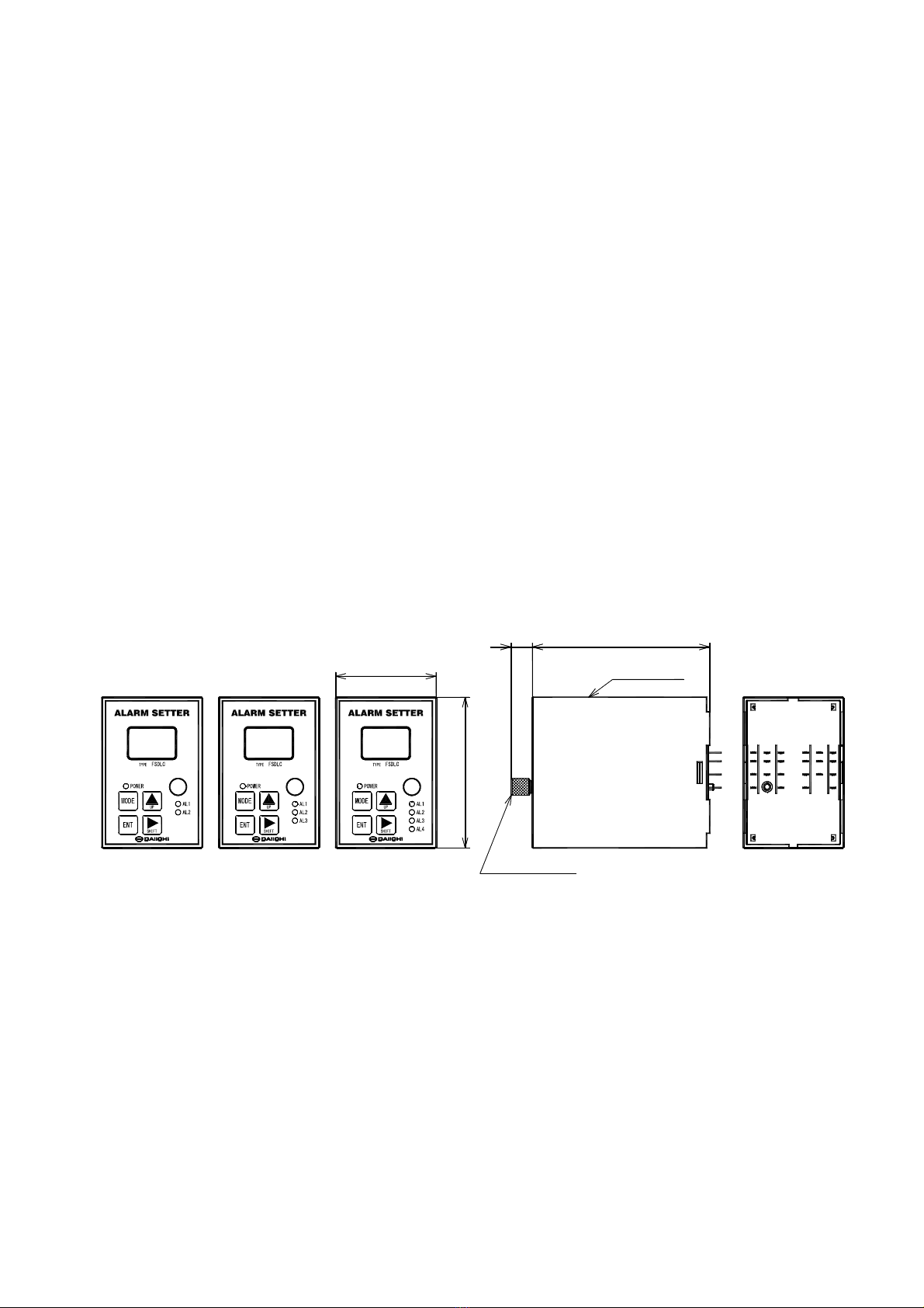
These products are not a dustproof, waterproof, and splash proof construction.
Please avoid the place with much dust. Moreover, please install in the place not exposed to rain or
water drop.
Please do not install in the place where sunlight hits directly.
Discoloration and degradation of a name plate, and deformation of the case by the surface temperature
rise may occur.
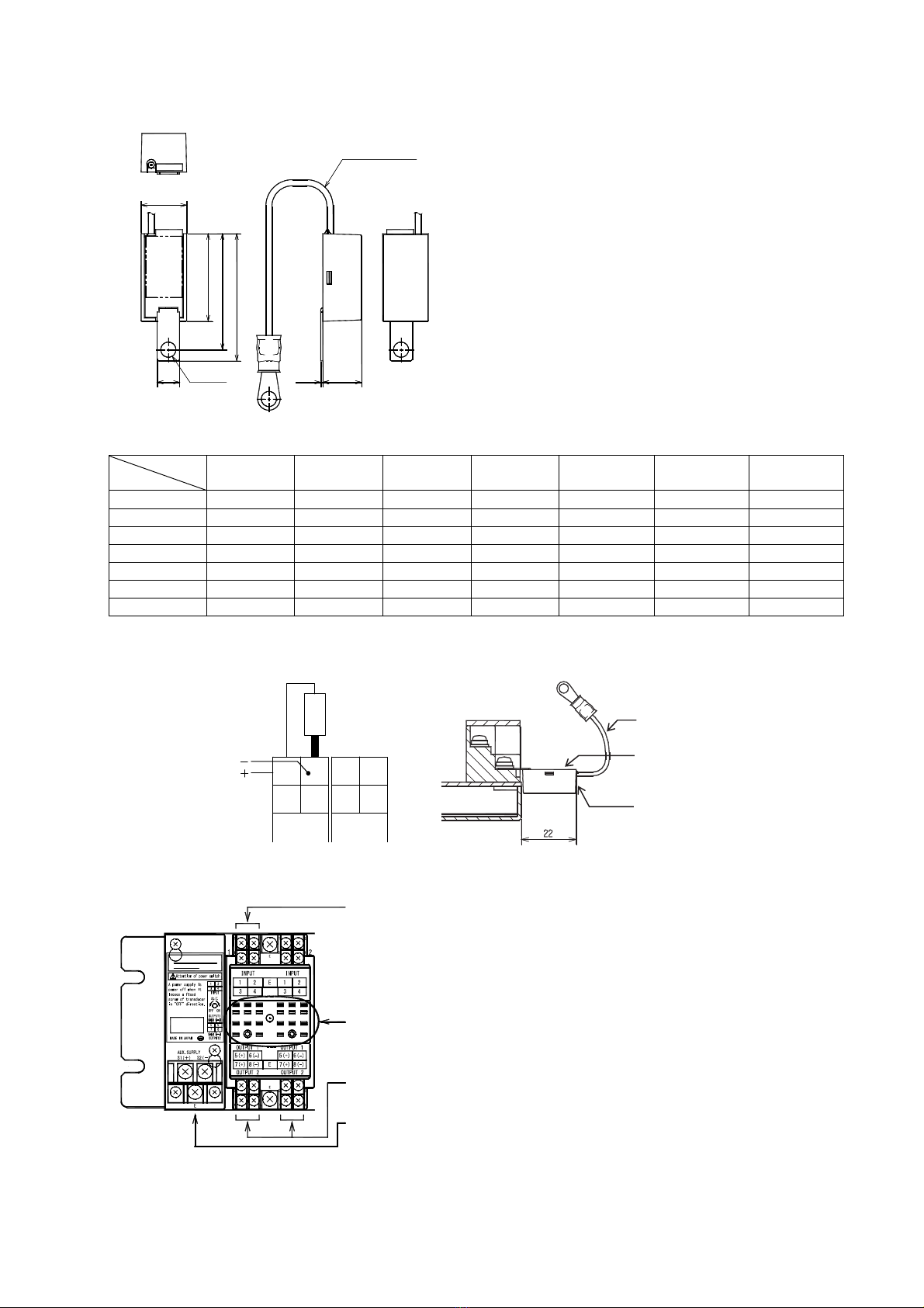
Mounting and wiring
Please refer to this instruction manual for mounting and the wiring.
Please refer to connection diagram for the wiring.
Please avoid hot line work.
Please use an electrical wire size suitable with the rated current.
Please check the tightening of the screw.
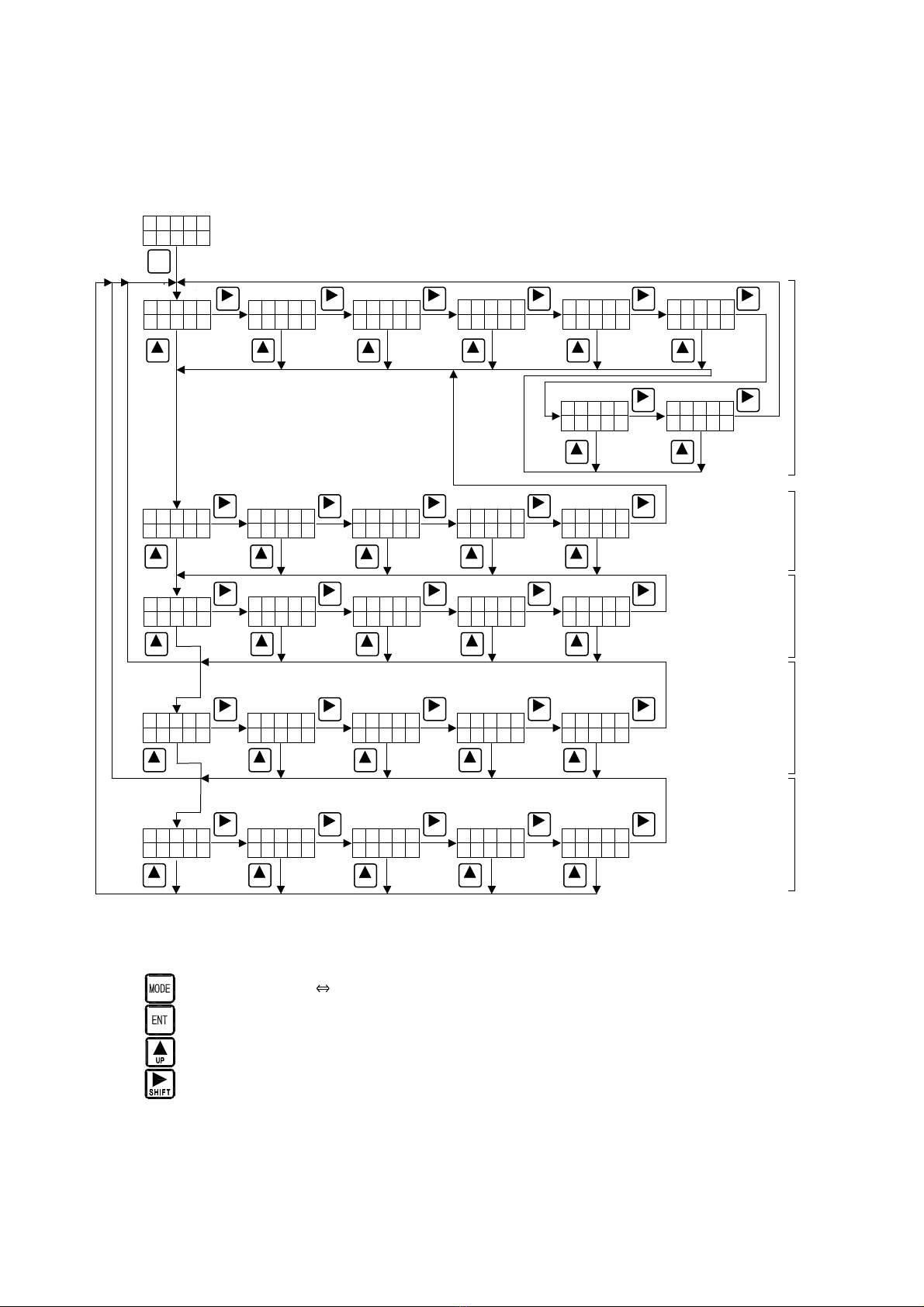
Preparation
This product must be set before use. Please set correctly after reading this instruction manual.
Maintenance and inspection
Inspection in energized state is dangerous.
This product does not include parts to be replaced at periodic inspection.
In case you need to check an input and control power supply by the hot line condition, please be warned
not to touch output wiring and a human body to other terminals.
Please make sure that the power LED (POWER) is lit properly.
Please regularly to see if wiring and mounting screws and fixing screws are not loose.
Please wipe off lightly with the dry soft cloth. Please do not use the organic solvent, chemicals, cleaners,
etc., such as an alcohol, for cleaning.
Storage
Please store in a place that meets the following conditions.
The ambient temperature within -25 to +70 ℃ (storage temperature).
Daily average temperature 40 ℃ or less.
Location corresponding to the usage environment and use conditions.
Location that is not affected by vibration and shock.
Aluminum electrolytic capacitors are used in products. Please energize the power supply within one year
after purchase.
Countermeasures against troubles
If trouble occurs within the warranty period, DAIICHI ELECTRONICS will repairs this product.
Disposal
Please dispose this product as industrial waste (non-combustible).
Mercury parts and a nickel-cadmium battery are not used for this product.
Warranty period
The warranty period of the product is one year after the date of delivery.