manuals.online logo
Brands
  1. Home
  2. •
  3. Brands
  4. •
  5. Daikin
  6. •
  7. Air Conditioner
  8. •
  9. Daikin BDU510B250VM User manual

Daikin BDU510B250VM User manual

Packaged Air Conditioner Drain Pump Kit
BDU510B250VM
4P590204-1
Installation manual
Packaged Air Conditioner Drain Pump Kit - BDU510B250VM
1
Read these instructions carefully before installation. Keep this manual in a handy place for future reference.
The original documentation is written in English. All other languages are translations.
CONTENTS
1. COMPONENTS 1
2. PREPARATION FOR INSTALLATION 1
3. INSTALLATION PROCEDURE 2
4. DRAINAGE PIPE INSTALLATION 4
5. ELECTRICAL WIRING 4
6. TRIAL OPERATION PROCEDURE 5
7. CHECK AFTER INSTALLATION 7
8. MAINTENANCE 7
1. COMPONENTS
Check that the following accessories are provided and that each accessory is correct in amount.
PRECAUTION
The accessories are required for the installation of the air conditioner. Be sure to keep them until the installation work is completed.
Name Drain Pump assembly Hanging bracket Drain connecting pipe 1 Drain connecting pipe 2 Drain connecting pipe 3
Shape
Quantity 1 2 1 1 1
Name Heat insulating tube 1 Heat insulating tube 2 Heat insulating tube 3 Heat insulating tube 4
Heat insulating material 1
Shape
ID38 x L35 ID38 x L125 ID38 x L114 ID38 x L94 60 x 290
Quantity 1 1 1 1 3
Name
Heat insulating material 2 Heat insulating material 3 Heat insulating material 4
Mounting screw Hose band
Shape
20 x 400 230 x 250 90 x 240 M5x12
Quantity 2 1 1 8 3
Name Cable tie 1 Cable tie 2 Plastic band Installation manual
Shape
L265 L150
Quantity 1 1 1 1
2. PREPARATION FOR INSTALLATION
2.1 Required Installation Space
To install an indoor unit with the drain pump kit, a clearance of 560mm or more is required between the ceiling slab and the ceiling surface
(Refer to fi gure below). Provide an inspection hatch in a position where you can readily service the indoor unit and the drain pump kit.
Ceiling slab
Indoor unit
min. 20mm
50mm
560mm or more
min. 70mm
Ceiling surface
Drain pump kit
Side View
The bottom surface of the drain pump kit will be
lower than the bottom surface of the indoor unit
Indoor unit
Approx. 150
Drain pump kit
Inspection hatch
(600mm X 600mm)
650 or more
(Service space)
Top View
2
Packaged Air Conditioner Drain Pump Kit - BDU510B250VM
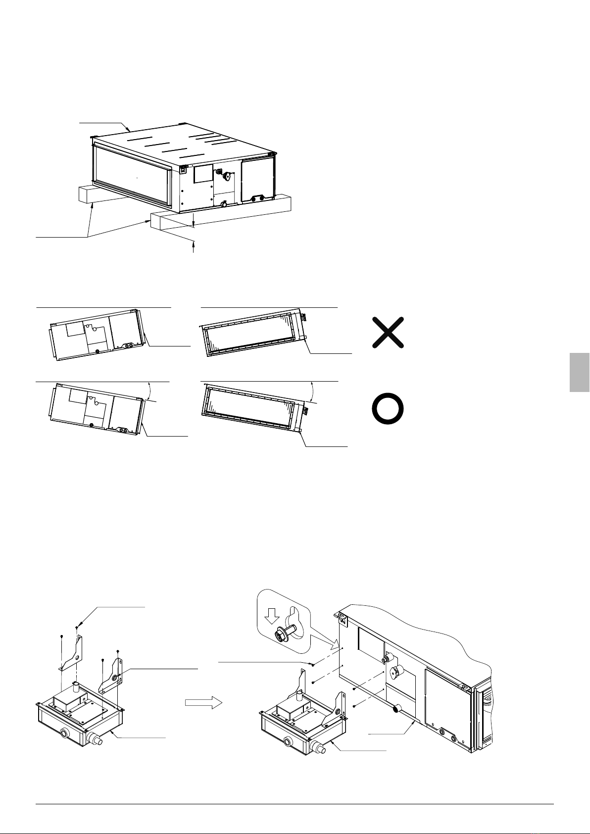
2.2 Drain Pump Kit Installation
Be sure to install this drain pump kit after installing the indoor unit to the ceiling.
Failure to follow this instruction may result in damage to the drain pump kit.
Note: The bottom surface of the drain pump kit will be lower than the bottom surface of the indoor unit.
If this drain pump kit must be installed before the indoor unit is installed to the ceiling, place the indoor unit on wood timbers etc.
After installing the drain pump kit, install the indoor unit carefully. Do not push, pull or apply excessive force to drain pump kit, it may damage
and cause water leakage.
Indoor unit
Wood timbers 120mm or more
CAUTION
To ensure the proper installation of the drain pump kit, please take note the following consideration when installing the indoor unit.
• Be sure that the suction side or drain socket side of the indoor unit is not at higher side of unit. Otherwise, the fl oat switch may
malfunction, causing water leakage or other failure.
Suction Side
Suction Side
1° or less 1° or less
(Indoor unit)
Drain Socket
(Indoor unit)
Drain Socket
3. INSTALLATION PROCEDURE
CAUTION
• Do not hold the drain pump kit by the drain socket when installing it to the indoor unit. Doing so may apply excessive force to the root
of the socket, resulting in water leakage.
• Do not give an excessive load up and down, when pulling and inserting the drain plug.
• Be sure to turn OFF the power to the indoor unit before starting the procedure below.
1. Assemble two hanging brackets (included) to the drain pump kit using mounting screw (included).
2. Pre-tighten mounting screw (included) at four prepared holes at unit side panel.
3. Mount the drain pump kit to the four pre-tightened screws at unit side panel, then tighten all the screws to fi x the drain pump kit to side panel.
(included)
Screws (4pcs.)
Rubber bush
Indoor unit
Drain pump kit
(included at right
hanging bracket only)
(included)
Pre-tighten screws (4pcs.)
Indoor unit
Drain pump kit
4. Insert heat insulating tube 1 (included) onto indoor unit drain socket.
5. Wrap the threaded end of the drain connecting pipe 1 (included) with thread seal tape. Then attach the drain connecting pipe 1 to the indoor unit
drain socket.
Packaged Air Conditioner Drain Pump Kit - BDU510B250VM
3
6. Insert heat insulating tube 2 (included) onto drain connecting pipe 1.
Drain pump kit
Indoor unit drain socket
Heat insulating tube 1 (included)
Drain connection pipe 1 (included)
Heat insulating tube 2 (included)
7. Insulate drain connecting pipe 2 (included) with heat insulating tube 3 (included), heat insulating tube 4 (included) and heat insulating material 1.
Note: Be sure to apply glue around the join of heat insulating tube 3 and heat insulating tube 4.
8. After glue dry, affi x heat insulating material 1 (included) to cover the join area.
Drain connection pipe 2
(included)
Heat insulating tube 4
(included) Heat insulating tube 3
(included)
Apply glue around the
joint of insulating area
60mm
(¿ eld supply)
(included)
Heat insulating material 1
(included)
Wrap around the joint
of insulating area
9. Connect the drain connecting pipe 2 to the drain pump kit and the drain connecting pipe 1.
Note: Be sure to connect the elbow side of the drain connecting pipe 2 to the drain pump kit.
10. Clamp the pipe joints with the hose bands (included).
11. Wrap heat insulating material 2 around the drain connecting pipes at hose band location. Then wrap the drain connecting pipes with heat
insulating materials 3 and heat insulating material 4. And fi nally wrap the exposed heat insulating tube with heat insulating material 1.
Indoor unit
Drain pump kit
Hose band
(included)
Drain connection pipe 2
(included)
Align to side
Heat insulating
material 2
(included)
Align to side
(included)
Heat insulating material 4 Heat insulating material 3
(included)
Joint of insulating area
Heat insulating material 1
(included)
(exposed heat insulating tube)
20mm
Drain connection pipe 1
(included)
90mm
60mm
20mm
230mm
60mm
12. Connect the drain connecting pipe 3 (included) to the outlet of the drain pump kit.
Note: Be sure to incline the external drain pipe downward.
13. Clamp the pipe joints with the hose bands (included).
14. Do not install the heat insulating material (fi eld supply) to the outlet of the drain pump kit at this point. It will be installed after the draining check
in the trial operation procedure (Refer to 6. TRIAL OPERATION PROCEDURE).
Drain pipe
(¿ eld supply)
(included)
Drain connection pipe 3
Indoor unit
Hose band
(included)
Drain pump kit
4
Packaged Air Conditioner Drain Pump Kit - BDU510B250VM
4. DRAINAGE PIPE INSTALLATION
Install the drain pipe to ensure proper drainage.
1. Use a pipe diameter equal to or larger than that of the connecting pipe (PVC pipes with a nominal diameter of 25mm and an external diameter
of 32mm).
2. Make the pipe length as short as possible and incline the pipe downward at a ratio of 1/100 or greater to prevent the accumulation of air.
3. Install pipe supports at intervals of 1.0m to 1.5m to prevent defl ection.
4. Use a new drain hose and hose bands when replacing the drain pump kit with a new one.
1~1.5m 1~1.5m
Pipe support
CAUTION
• The height of the drain-up pipe must be 750mm or less relative to the indoor unit drain outlet.
• The rising drain-up pipe must be installed vertically.
Ceiling slab
1~1.5m Pipe support
(Field supply)
Drain-up piping
750mm or less
• Refer to the fi gure below for concentrated drain piping.
750mm or less
5. ELECTRICAL WIRING
Perform electrical wiring for the drain pump kit properly as follows.
CAUTION
• Be sure to turn OFF the power to the indoor unit before starting the procedure below.
1. Remove the indoor unit control box cover.
2. Insert drain pump and fl oat switch lead wires through the rubber bush on the hanging bracket. Route and connect the lead wires to the printed
circuit board of the indoor unit (Refer fi gure below).
3. Bind the lead wires together with the drain connecting pipe 1 (included) using cable tie 1 (included).
Note: Do not compress the insulation after install the cable tie. Be sure the lead wire is fi xed close to the indoor unit.
4. Clamp the lead wires inside control box using cable tie 2 (included) and plastic band (included), along the path to PCB, secure with other
hardness wires fi xing band (Refer to fi gure below).
5. Remove the short circuit connector from the X15A terminal on the indoor unit printed circuit board (A1P).
6. Connect the fl oat switch lead wire to the X15A terminal.
7. Connect the drain pump lead wire to the X25A terminal.
8. After completion of the wiring, be sure to organize the wires neatly, bind together and clamp the wires.
9. Install back the indoor unit control box cover.
Packaged Air Conditioner Drain Pump Kit - BDU510B250VM
5
Connector X15A
Connector X25A
Indoor unit
(included)
Rubber bush
Wires Clamp
(inside control box)
Drain pump and À oat
switch lead wires
Control box
(included)
Cable tie 2 and Plastic band
Drain connection pipe 1
(included)
Cable tie 1
DRAIN PUMP LEAD WIRE
X25A X15A
INDOOR UNIT PRINT
MP
CIRCUIT BOARD
INDOOR UNIT
DRAIN PUMP ASSY
SWITCH
FLOAT
LEAD WIRE
FLOAT SWITCH
6. TRIAL OPERATION PROCEDURE
CAUTION
• Be sure to turn OFF the power to the indoor unit before starting the procedure below.
1. Check again that the installation and electrical wiring procedures for the drain pump kit have been completed properly.
2. Remove the inspection port cover from the drain pump kit and service panel from the Indoor unit (Refer to fi gure below).
Indoor unit
Drain pump kit
Inspection port cover
Screws (4pcs.)
Service panel
Screws (7pcs.)
3. To check the drain condition of the drain pump kit, pour approximately 3 litres of water from the service panel opening into drain pan
(Refer to fi gure below).
4. Ensure that the water fl ows out smoothly without leakage.
6
Packaged Air Conditioner Drain Pump Kit - BDU510B250VM
Indoor unit
Drain pump kit
Paraf¿ n heater siphon
Bucket
■IF ELECTRICAL WIRING HAS BEEN COMPLETED:
5. After making sure that the indoor unit control box cover is closed, turn ON the power.
6. Use the remote controller to perform COOL operation and check the drain condition by pressing upward the drain connecting pipe 3 (included).
NOTE:
• If using a VAV type air conditioner, you may not be able to perform COOL operation unless trial operation of the outdoor unit is completed.
In this case, check the drain condition by performing COOL operation during or after trial operation of the outdoor unit.
7. After checking the drain condition, stop the COOL operation and reinstall the service panel and the inspection port cover.
■IF ELECTRICAL WIRING HAS NOT BEEN COMPLETED:
5. Remove the indoor unit control box cover, connect the remote controller to P1 and P2 terminal of the operation terminal block (X2M).
Connect a single-phase 220V~240V power supply and earth wire to the L, N and earth terminal of the power terminal block (X1M).
Then close the indoor unit control box cover and turn ON the power.
6. Use the remote controller to start trial operation mode and select FAN operation mode with the operation mode button.
7. Press the ON/OFF button to start the drain pump. Press upward the drain connecting pipe 3 (included) to check the drain condition
(Refer to fi gure below).
CAUTION
• Be careful as pressing the ON/OFF button causes the indoor unit fan to rotate.
8. After completion of the drain condition check, turn OFF the power. Then disconnect the remote control wire and the earth wire, and close the
control box cover.
9. Reinstall the service panel and the inspection port cover.
Drain connecting pipe 3
(included)
Outlet socket
Drain pump kit
Drain pump kit
Check the drain condition by
pressing the drain connecting
pipe 3 (included) upward
Screws (4pcs.)
Inspection port cover
■AFTER TRIAL OPERATION COMPLETED:
1. Reinsert the drain connecting pipe 3 (included) all the way and clamp it with a hose band (included).
Note: Be sure that there is no gap between the drain connecting pipe 3 (included) and the drain pump kit.
2. Insulate the drain connecting pipe 3 (included) with insulation tube (fi eld supply) to prevent dew condensation.
Packaged Air Conditioner Drain Pump Kit - BDU510B250VM
7
Insulation tube
(Field supply)
No gap allowed
Drain pump kit
CAUTION
Wrap the heat insulating material
to adequately insulate the hose
band
7. CHECK AFTER INSTALLATION
Check again at the least the following items after completion of installation.
Check Item Check Mark
Are the indoor unit and the drain pump kit installed horizontally?
Is the drain pipe connected fi rmly?
Is there no possibility of water leakage?
Is the drain piping properly inclined downward (1/50 to 1/100)?
Is the drain hose adequately insulated?
Are the wires connected correctly?
8. MAINTENANCE
Clean the drain pump kit at the end of every season in which the unit is used for cooling.
1. Drain all the water out of the drain pump kit by removing the insulation plug and rubber plug.
Note: Even after removing the rubber plug from the drain pump kit, some water may remain trapped in the drain connecting pipes
and the drain pump kit.
2. Remove the inspection port cover from the drain pump kit.
3. Remove dust and water in the areas around the inspection port.
4. After fi nish cleaning, install back the inspection port cover, rubber plug and insulation plug.
Drain pump kit
Rubber plug
Insulation plug
Screws (4pcs.)
Inspection port cover
4P590204-1 2019.07
Copyright 2019 Daikin

Other Daikin Air Conditioner manuals

Daikin RXTM30R2V1B How to use

Daikin

Daikin RXTM30R2V1B How to use

Daikin Altherma 3 R ECH2O How to use

Daikin

Daikin Altherma 3 R ECH2O How to use

Daikin REYQ72TTJU User manual

Daikin

Daikin REYQ72TTJU User manual

Daikin ARXF25C5V1B User manual

Daikin

Daikin ARXF25C5V1B User manual

Daikin FXSQ140P7VEB Setup guide

Daikin

Daikin FXSQ140P7VEB Setup guide

Daikin Super Multi NX FVXS50FV1B User manual

Daikin

Daikin Super Multi NX FVXS50FV1B User manual

Daikin Altherma 3 RW User manual

Daikin

Daikin Altherma 3 RW User manual

Daikin FUQ71CVEB User manual

Daikin

Daikin FUQ71CVEB User manual

Daikin 2MXS-W Series User manual

Daikin

Daikin 2MXS-W Series User manual

Daikin CTKC25WVMG User manual

Daikin

Daikin CTKC25WVMG User manual

Daikin RKM18PVMK User manual

Daikin

Daikin RKM18PVMK User manual

Daikin Altherma CHYHBH05AF User manual

Daikin

Daikin Altherma CHYHBH05AF User manual

Daikin FTXN24KVJU User manual

Daikin

Daikin FTXN24KVJU User manual

Daikin FMA50RVMA User manual

Daikin

Daikin FMA50RVMA User manual

Daikin EWAQ004BAVP User manual

Daikin

Daikin EWAQ004BAVP User manual

Daikin FCQ71DV3B User manual

Daikin

Daikin FCQ71DV3B User manual

Daikin RXA20A5V1B8 User manual

Daikin

Daikin RXA20A5V1B8 User manual

Daikin FVFC71AV16 User manual

Daikin

Daikin FVFC71AV16 User manual

Daikin FBA35A2VEB9 Product information sheet

Daikin

Daikin FBA35A2VEB9 Product information sheet

Daikin FT13BV1LS User manual

Daikin

Daikin FT13BV1LS User manual

Daikin Altherma EHVZ-D9WG User manual

Daikin

Daikin Altherma EHVZ-D9WG User manual

Daikin RMXS48LVJU User manual

Daikin

Daikin RMXS48LVJU User manual

Daikin CTXM15M2V1B User manual

Daikin

Daikin CTXM15M2V1B User manual

Daikin FTXM20UVMA User manual

Daikin

Daikin FTXM20UVMA User manual

Popular Air Conditioner manuals by other brands

Samsung AS18BPAN Service manual

Samsung

Samsung AS18BPAN Service manual

Star Progetti Brezza 170 instruction manual

Star Progetti

Star Progetti Brezza 170 instruction manual

Carrier 40TGV0131UP Service manual

Carrier

Carrier 40TGV0131UP Service manual

Samsung Wall Mounted Type Series user manual

Samsung

Samsung Wall Mounted Type Series user manual

Magnavox W-08CR user manual

Magnavox

Magnavox W-08CR user manual

Whirlpool FM07IDU32 Instructions for use

Whirlpool

Whirlpool FM07IDU32 Instructions for use

Friedrich C24YF Installation instruction sheet

Friedrich

Friedrich C24YF Installation instruction sheet

CIAT 42HV09JSC user manual

CIAT

CIAT 42HV09JSC user manual

Linea 2000 DOMO DO1037A Instruction booklet

Linea 2000

Linea 2000 DOMO DO1037A Instruction booklet

Heiko CA070-A1 installation manual

Heiko

Heiko CA070-A1 installation manual

Gree GPH12AO-K5NNA1A owner's manual

Gree

Gree GPH12AO-K5NNA1A owner's manual

Hitachi RAS-S18CPZ instruction manual

Hitachi

Hitachi RAS-S18CPZ instruction manual

Appliance ACW-2000 R Important Instruction/User Manual

Appliance

Appliance ACW-2000 R Important Instruction/User Manual

Zenith ZW5010 owner's manual

Zenith

Zenith ZW5010 owner's manual

Toshiba RAV-103TUH-PE Service manual

Toshiba

Toshiba RAV-103TUH-PE Service manual

ariazone 5001 Operator's manual

ariazone

ariazone 5001 Operator's manual

York LATITUDE JP024-060 installation manual

York

York LATITUDE JP024-060 installation manual

Hitachi RAS-PH18PHLAE Service manual

Hitachi

Hitachi RAS-PH18PHLAE Service manual

manuals.online logo
manuals.online logoBrands
  • About & Mission
  • Contact us
  • Privacy Policy
  • Terms and Conditions

Copyright 2025 Manuals.Online. All Rights Reserved.