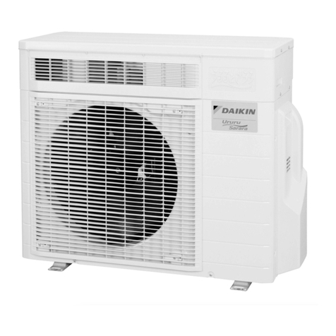
ERAP110~170MBYNN
Air-cooled condensing units
4PW22681-1
Operation manual
4
■High pressure switch
Each circuit is protected by two high pressure switches (S*PH)
which measure the condenser pressure (pressure at the outlet
of the compressor). They are installed in the compressor
housing of the circuit. When the pressure becomes too high, the
pressure switches are activated and the circuit stops.
The switches are factory-set and may not be adjusted. When
activated, they must be reset by means of a screwdriver. The
controller still needs to be reset.
■Reverse phase protector
The reverse phase protectors (R*P) prevent the screw
compressors from running in the wrong direction. If the
compressors do not start, two phases of the power supply must
be inverted.
Internal wiring - Parts table
Refer to the internal wiring diagram supplied with the unit. The
abbreviations used are listed below:
A1 ...............** ....... Current transfo/A-meter
A1P........................ PCB-controller
B1P........................ Low pressure transmitter
B2P........................ High pressure transmitter
C1~C3 ................... Capacitor
E1HC..................... Crankcase heater compressor
E3H........................ Evaporator heater
F1U~F3U....# ........ Main fuses
F4U,F5U .....# ........ Fuses for evaporator heater
F6B........................ Fuse for primary of TR1
F7B........................ Fuse for secondary of TR1
F8U........................ Surge proof fuse for A1P
F9B........................ Fuse for secondary of TR2
F12B...................... Fuse for fanmotors
H1P.............*......... Indication lamp general operation
H2P.............*......... Indication lamp alarm
H3P.............*......... Indication lamp operation compressor
H5P.............*......... Changeable output
J1........................... Power supply
J11......................... RS485 connection
J2,J3,J6 ................. Analog input
J5,J7,J8 ................. Digital input
J12~J18................. Digital output
K1M ....................... Linecontactor
K2M ....................... Deltacontactor
K3M ....................... Starcontactor
K7F~K9F ............... Fancontactor
K17S...................... Overcurrent relay
K1A........................ Auxiliary relay for safeties
K2A........................ Auxiliary relay compressor thermal protector
K3A........................ Auxiliary relay for discharge thermal protector
K7A........................ Auxiliary relay for safety high pressure
L1,L2,L3................. Main supply terminals
M11F-M14F........... Fan motors
M1C....................... Compressor motor
M1S ....................... Stepless capacity control for compressor
PE.......................... Main earth terminal
Q11F~Q14F .......... Thermal protectors fan motors
Q1M....................... Thermal protector compressor motor
R1.......................... Auxiliary resistance for feedback
R1F ........................Feedback resistance
R1P........................Reverse phase protector
R4T ........................Sensor for thermostat
R5T ........................Sensor for ambient temperature
S1PH......................High pressure switch
S3T ........................Discharge thermal protector
S5E ........................Emergency stop push button
S6S ............ * .........Changeable switch for remote function
(e.g. remote start/stop)
S8L.........................Flowswitch
S9L............. #.........Contact that closes if the fan/pump is working
S10S .......... * .........Changeable switch for remote function
(e.g. dual setpoint)
S11S .......... * .........Changeable switch for remote function
(e.g. enable/disable capacity limitation 1)
S12S .......... * .........Changeable switch for remote function
(e.g. enable/disable capacity limitation 2)
S13S .......... ##.......Main isolator switch
S14PH....................High pressure switch
TC01,TC02 ............Optocoupler (analog to digital signal)
TR1 ........................Transfo control circuit
TR2 ........................Transfo supply controller + digital inputs
V1...........................V-meter
Y11S ......................12% capacity step for compressor
Y15S ......................Liquid injection valve of the compressor
Y16S ......................Liquid line solenoid valve
BEFORE OPERATION
Checks before initial start-up
After the installation of the unit, check the following before switching
on the circuit breaker:
1Field wiring
Make sure that the field wiring between the local supply panel
and the unit has been carried out according to the instructions
described in the installation manual, according to the wiring
diagrams and according to European and national regulations.
2Additional interlock contact
Additional interlock contacts (S*L) must be provided (e.g.
flowswitch, contact of pump motor contactor). Make sure that
they have been installed between the appropriate terminals
(refer to the wiring diagram supplied with the unit). They must be
normal open contacts.
3Fuses or protection devices
Check that the fuses or the locally installed protection devices
are of the size and type specified in the installation manual.
Make sure that neither a fuse nor a protection device has been
bypassed.
Not included with standard unit
Not possible as option Possible as option
Obligatory # ##
Not obligatory * **
Make sure that the circuit breaker on the power supply
panel of the unit is switched off.

