Daikin KEH041A42 User manual

• Request the dealer or an authorized technician to install the product.
Improper installation of the product could result in water leakage, an electrical shock, or fire.
• Inform customers that they should store this Installation Manual for future reference.
• After completing the installation, make sure that the unit operates properly during the startup operation.
• All phases of the field-installation, including, but not limited to, electrical, piping, and safety, must be done in accordance with manufacturer’s
instructions and must comply with national, state, provincial, and local codes.
• This product is a heater designed to melt snow that is blown into the product from the outside to prevent the drain pan of the outdoor unit from
freezing.
• Install the product with a snow-break hood on a high stand if this product is used in heavy snow areas.
• The product must be installed according to the instructions given in this manual.
The Incomplete installation of the product could result in water leakage, an electrical shock, or fire.
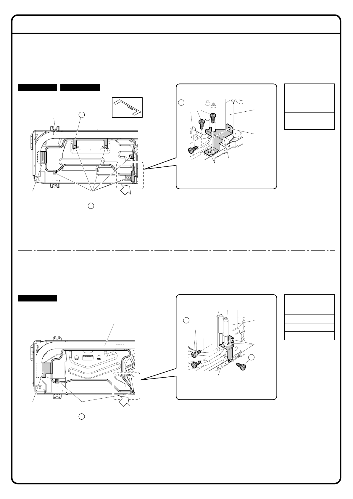
• Use the supplied or specified installation parts.
Use of other parts could result in the unit becoming loose and falling, water leakage, electrical shocks, or fire.
• Turn OFF the power supply at the time of installation.
Touching any electrical parts may with the power supply turned on could result in electrical shocks.
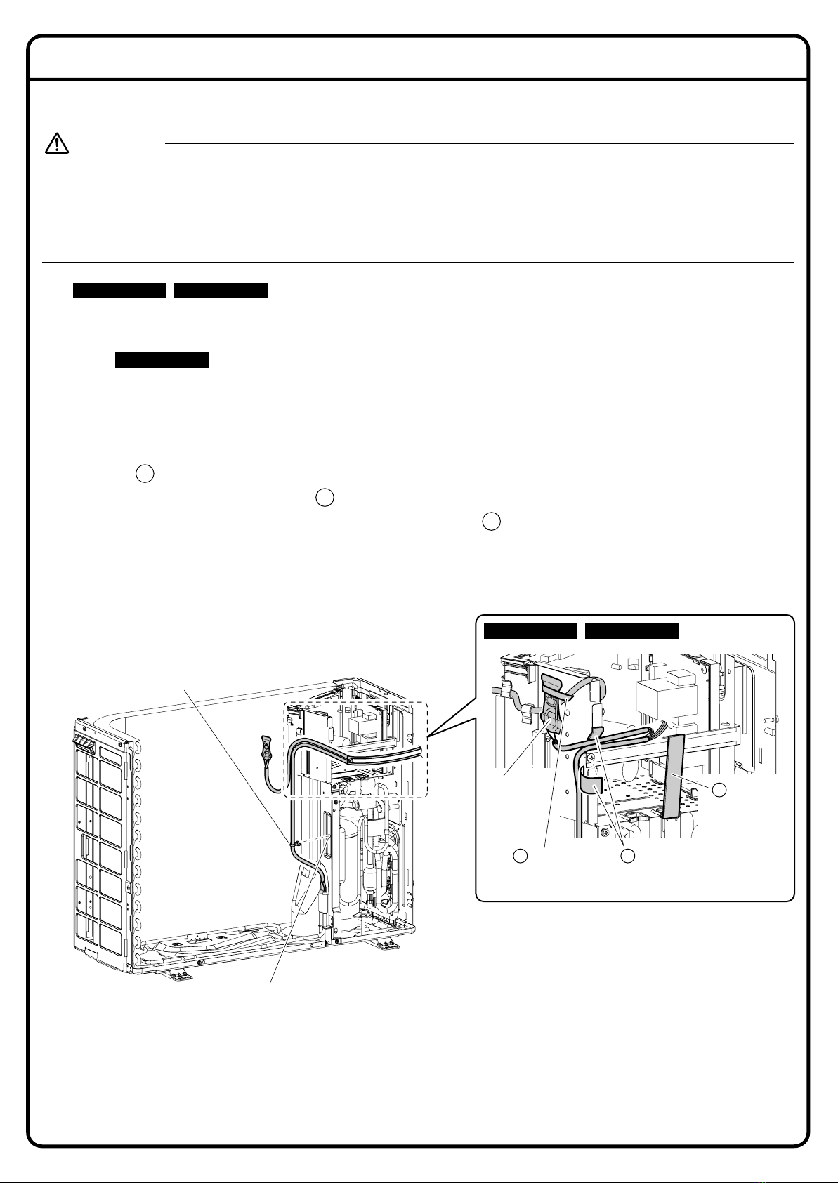
• Use specified wires. Connect and fix the wires so that the wires will not put improper force on the terminal junctions.
Wires connected or fixed improperly could result in terminal overheating, an electrical shock, or fire.
• When wiring and connecting the indoor and outdoor units, carefully arrange the wiring so that they will not put improper
force on the structures.
Install covers over the wires. Incomplete cover installation could result in terminal overheating, an electrical shock, or fire.
• Wear protective gloves at the time of installation.
Touching the suction mouth or aluminum fin of the outdoor unit may result in injury.
• Do not install the product in places where there is danger of exposure to inflammable gas leakage.
If the gas leaks and builds up around the unit, it may catch fire.
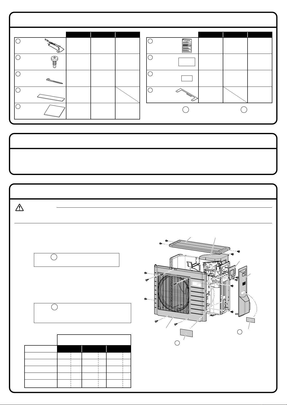
• Do not grab the top plate of the outdoor unit carelessly when removing the top plate.
The sharp edge of the top plate may cause injury.
• Do not install the outdoor unit in places where small animals may nest in the outdoor unit.
If small animals intrude and touch the internal parts of the outdoor unit, the outdoor unit may malfunction, generate smoke, or ignite.
Advise the user to keep the place clean.
• Do not touch the heater unit with bare hands.
The temperature of the heater unit will become high when the heater is turned on.
Touching the heater unit with bare hands may result in burns or injury.
WARNING
CAUTION
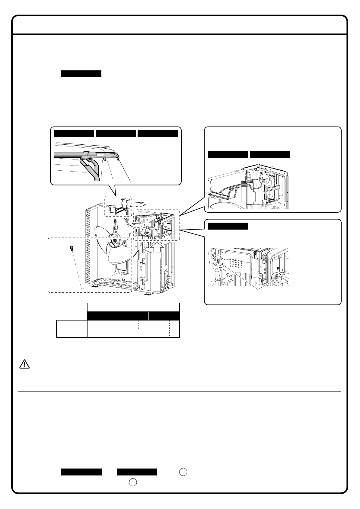
• Do not touch the heater unit without wearing gloves.
The temperature of the heater unit will become high when the heater is turned on.
Touching the heater unit with bare hands will result in burns or injury.
DANGER
Read these SAFETY CONSIDERATIONS carefully before installing the drain pan heater. After completing the installation, check if the unit operates
properly during the start-up operation.
Meaning of DANGER, WARNING and CAUTION symbols.
2P326981-2 M12B192
Safety Considerations for Installation of Drain Pan Heater
DRAIN PAN HEATER
Two-dimensional bar code
is a code for manufacturing.
MODELS: KEH041A42, KEH041A47, KEH041A48
Indicates an imminently hazardous situation which, if not
avoided, will result in death or serious injury.
Indicates a potentially hazardous situation which, if not
avoided, could result in death or serious injury.
Indicates a potentially hazardous
situation which, if not avoided, may
result in minor or moderate injury. It
may also be used to alert against
unsafe practices.
DANGER
WARNING
CAUTION

KEH041A47 KEH041A48KEH041A42
111
747
222
11
222
KEH041A47 KEH041A48KEH041A42
111
111
111
11
1. Remove each component of the
outdoor unit.
1) Remove the stop valve cover.
• Affix J information label near the
manufacture’s label. *I
2) Remove the service lid.
3) Remove the top plate.
4) Remove the anti-drip cover, if included.
5) Remove the front plate.
• Affix H electric wiring diagram label
where there is enough space available
on the back of the front plate. *II
• Be sure to check that the power supply of the product is turned off.
WARNING
Drain pan
heater
A
Piercing
screw
B
Binding band
D
Sealing material (long)
E
Sealing
material
(square)
F
Installation
manual
G
Electric wiring
diagram label
H
Information
label
J
Fixing plate
K
• The appearance of the outdoor unit
and the number of screws may differ
from some models.
J
H
Number and type of
screws to be removed
Parts name
Stop valve cover
Service lid
Top plate
Anti-drip cover
Front plate
1
2
4
–
6
*1
*1
*2
–
*1×1
*2×5
1
2
3
–
7
*1
*2
*2
–
*2
2
2
4
–
5
*1
*1
*2
–
*2
KEH041A42 KEH041A47 KEH041A48
Appearance of A drain pan heater and K fixing
plate may differ from some models.
A K
Accessories
Installation Procedure (1)
*1 Truss head
tapping screw.
*2 Hexagon
tapping screw.
Top plate Anti-drip cover
Service lid
Stop valve
cover
J Information
label *I
H Electric wiring
diagram label *II
Front plate
Tools Required for Installation
• Electric drill
• ø1/8” (ø3.2mm) drill
• ø5/32” (ø4mm) drill
• Phillips screwdriver
• Nippers

A
B
C
3. Installation of the drain pan heater.
• When drilling a hole, be careful not to damage the soundproofing material and other components on the
back side.
CAUTION
2. Remove the fan motor base.
1) Remove the fixing screw at the lower section of the fan motor base, and remove the fan motor base
together with the propeller fan. See Fig.1.
• For KEH041A48 , the motor base cannot be removed. Remove the 2 screws from the electrical
wiring box, lift the motor base, and install the heater. See Fig.2
• Do not remove the fan motor harness.
• Be careful so that the fan motor harness does not come into contact with the edges of the heat
exchanger or other components.
• Place the removed fan motor base so that stress is not applied on the propeller fan.
• Make the ground plate closely adhere to the partition.
• Install the drain pan heater in a position where it does not come into contact with the fan motor base.
1) To fix the drain pan heater, drill ø1/8” (ø3.2mm) holes in the bottom frame and the partition plate.
(Refer to Installation Procedure (3) for the parts for drilling and the number of holes.)
• Place the actual components to ensure positioning is correct before drilling holes.
• The hole can be made with the included piercing-screw as well.
2) Install the drain pan heater.
• Insert the plate under the heat exchanger.
• For KEH041A42 and KEH041A48 , place K fixing plate.
3) Fix the drain pan heater with B piercing screw.
KEH041A42 KEH041A48 K
B
Screw *3
Fig. 1
Appearance of the outdoor unit
may differ from some models.
KEH041A42
KEH041A42 KEH041A47
KEH041A48
KEH041A47 KEH041A48
The lugs of the
fan motor base
are hooked on
the heat
exchanger.
View A
The fan motor
harness is fitted in
the groove of the
partition plate.
Remove the 2 screws from the electrical wiring box, lift the
motor base, and install the heater.
Condition of fan motor harness
installation
Groove
2 screws *1
View B
View C
Installation Procedure (2)
*1 Truss head
tapping screw.
*2 Hexagon
tapping screw.
*1 Truss head
tapping screw.
KEH041A42 KEH041A47 KEH041A48
Number and type of screws to be removed
*3 Screw type
SPLIT
MULTI SPLIT
2*11*21*1
2*1––
Fig. 2
KEH041A48

D
D
KEH041A42 KEH041A48
KEH041A47
Parts for drilling and
number of ø1/8”
(ø3.2mm) holes
Bottom frame 6
Partition plate 1
Total 7
Parts for drilling and
number of ø1/8”
(ø3.2mm) holes
Bottom frame 2
Partition plate 2
Total 4
View D
B Piercing
screw
B Piercing
screw
View D
Installation Procedure (3)
Partition
plate
Ground plate:
Make the ground
plate closely adhere
to the partition.
Hole
Hole
Partition
plate
Ground plate:
Make the ground plate closely
adhere to the partition.
Hole
Heat exchanger
Heat exchanger
Hole:
Fix with
B piercing screw.
B
K Fixing plate
Plate:
Insert the plates
under the heat
exchanger.
Plate:
Insert the plates
under the heat
exchanger.
Hole:
Fix with
B piercing screw.
B
Fix the fixing plate by putting it into
contact with the heat exchanger.
B Piercing
screw

1) Drill a ø5/32” (ø4mm) hole in the partition plate for installing the snap band. (1 location)
2) Remove the sealing material from the partition plate.
• KEH041A47 only
• Dispose of the removed sealing material.
3) Install the fan motor base.
• Be careful not to confuse screw types. See Installation Procedure (2).
4) Insert the snap band into the drilled hole.
5) Affix F sealing materials (square) at 2 positions to protect the harness.
6)
Place the harness and affix the E sealing material (long) to fix it.
7) Bind the fan motor harness and the thermostat with the D binding band. (1 location)
• Cut the tip of binding band.
F
E
D
KEH041A42 KEH041A47
KEH041A42 KEH041A47
Installation Procedure (4)
4. Route the harnesses.
• When drilling a hole, be careful not to damage the soundproofing material and other components on the
back side.
• When drilling a hole in the partition plate, be careful not to let chippings drop on the electrical components
(particularly the reactor).
Operating the unit with chippings attached on the reactor may cause electrical shock or fire.
WARNING
Hole:
Drill a hole in alignment with the
actual component and at a
position where the harness will
not become loose or too tense.
Snap band
E Sealing
material
(long)
D Binding band F Sealing materials (square):
Attach to the screw and the
edge of the partition plate.
Thermostat
KEH041A47

B
C
Installation Procedure (5)
1) Drill ø5/32” (ø4mm) holes in the partition plate for installing the snap bands. (2 locations)
2) Insert the snap bands into the drilled holes.
3) Cut off the electrical wiring box and affix F sealing materials (square) at 2 positions to protect the
harness.
4) Insert the snap band into the hole in the electrical wiring box to fix it.
• Any of the holes can be used.
5) Fix the harness on the electrical wiring box with the D binding band.
• Cut the tip of binding band.
KEH041A48
D Binding band
View C
View B
Cut the electrical
wiring box.
F
D
F Sealing materials (square):
Attach to the edges of the
partition plate.
Snap band
Any of the holes
can be used.
Snap band Hole
Snap band Hole

Installation Procedure (6)
G
H
5. Connect the FastOn terminals of the drain pan heater to the terminal block of the outdoor
unit.
1) Connect the thermostat-side terminal (black harness) to the leftmost terminal and the heater-side
terminal (white harness) to the second leftmost terminal.
2) Install the fan motor base.
• Be careful not to confuse screw types. See Installation Procedure (2).
3) Bind the harnesses with the D binding band. (1 location)
• Cut the tip of binding band.
D
KEH041A42
KEH041A48
KEH041A47
Heater-side
terminal
(white harness)
Thermostat-
side terminal
(black harness)
View G
D Binding band
• The shape may slightly differ depending on the model.
View HIn the case of installation to the multi outdoor unit
Fix the round
terminal for the
drain pan heater to
the terminal board.
D Binding band
Thermostat-
side terminal
(black harness)
Heater-side
terminal
(white harness)
Ground terminal
Unsheathed
connecting cable
for the indoor unit
• After inserting the
cable, release your
hand to close and fix
the connection.
Push
How to connect to the relay
connector
1) Remove the connecting cable for the indoor unit from Terminals (1) and (2), cut off the round terminal,
and remove the sheath. (11/32”-7/16” (9-11mm))
2) Connect the cut connecting cable to the relay connector for the drain pan heater.
3) Fix the round terminal for the drain pan heater to the terminal board with the screw.
• Connect the thermostat-side terminal (black harness) to the leftmost terminal and the heater-side
terminal (white harness) to the second leftmost terminal.
4) Fix the extra portion of the harness and the fuse holder with the D binding band. (1 location)
• Cut the tip of binding band.
D

Installation Check (electrical test of the outdoor unit)
1 2 3
1. Check the following before powering on the unit.
1) Check whether the drain pan heater has been properly
installed, wiring has been properly performed, and the
removed components have been returned to the
original positions.
2) Check the insulation resistance of the drain pan
heater.
• Use the tester (500 VDC) to check that the insulation
resistance between 1 terminal and the ground
terminal and between 2 terminal and the ground
terminal is equal to or higher than 1MΩ.
3) Check the continuity of the outdoor unit.
• Use the tester to check that the continuity between
the screw on the front grille and the ground terminal
reads 0Ω.
• When there is no continuity, retighten the screws
securing the front plate and the bottom frame to
increase the area of contact with the screw. Then,
carry out the continuity test again.
2. Check the following after powering on the unit.
• Turn on the power supply and check that the temperature
of the drain pan heater will rise.
• Touch the bottom of the outdoor unit by hand and
check the temperature rise.
• If the outdoor temperature is high, the heater will not
be energized which is not a failure.
(Operation of thermo sensor: Turned on at 23˚F
(–5˚C) and off at 34˚F(1˚C).)
3. Install the remaining components to the original
positions.
• Be careful not to confuse screw types.
See Installation Procedure (1).
1) Install the service lid.
2) Install the stop valve cover.
• The drain pan heater is hot; do not touch it with bare hands.
CAUTION
1
2
Appearance of the outdoor
unit may differ from some
models.
2P326981-2
Ground terminal
1 terminal1
2 terminal
2
Screw of the front grille
Installation Procedure (7)
6. Install each component to the original position.
• Be careful not to confuse screw types. See Installation Procedure (1).
1) Install the front plate.
2) Install the anti-drip cover, if provided.
3) Install the top plate.
This manual suits for next models
2
Table of contents
Other Daikin Heater manuals

Daikin
Daikin KEH094A41E User manual

Daikin
Daikin EHXD User manual

Daikin
Daikin REYQ8-48PY1B User manual

Daikin
Daikin Altherma EKRTCTRL1 User manual

Daikin
Daikin DRC User manual

Daikin
Daikin KEH067A41E(A) User manual

Daikin
Daikin REYQ8-48PY1B User manual

Daikin
Daikin FWXV15AVEB User manual

Daikin
Daikin KEH041A43 User manual

Daikin
Daikin RDXYQ8T7V1B User manual

Daikin
Daikin Altherma 3 GEO Product information sheet

Daikin
Daikin Altherma 3 H HT F User manual

Daikin
Daikin Altherma 3 H F User manual

Daikin
Daikin FWXV15AVEB User manual

Daikin
Daikin AHKD 20 User manual

Daikin
Daikin KEH041A41 User manual

Daikin
Daikin Altherma 3 GEO EGSAX06UDA9W Product information sheet