manuals.online logo
Brands
  1. Home
  2. •
  3. Brands
  4. •
  5. Daikin
  6. •
  7. Heater
  8. •
  9. Daikin EHXD User manual

Daikin EHXD User manual

This manual suits for next models

3

Other Daikin Heater manuals

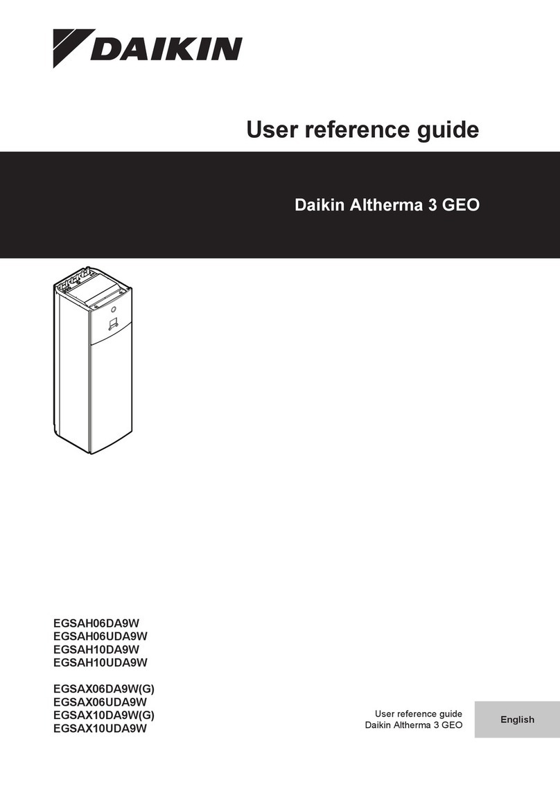
Daikin Altherma 3 H F User manual

Daikin

Daikin Altherma 3 H F User manual

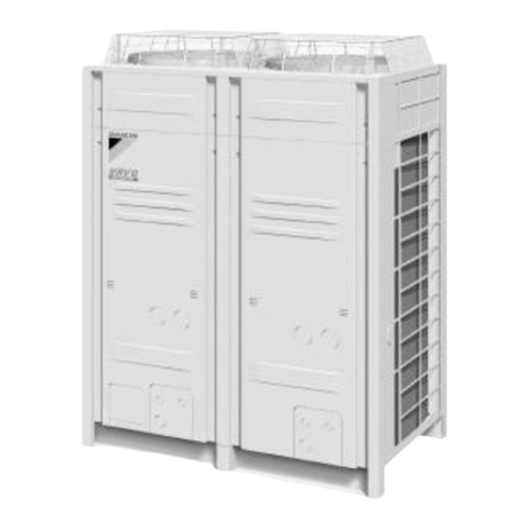
Daikin REYQ8-48PY1B User manual

Daikin

Daikin REYQ8-48PY1B User manual

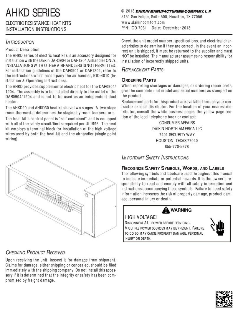
Daikin AHKD 20 User manual

Daikin

Daikin AHKD 20 User manual

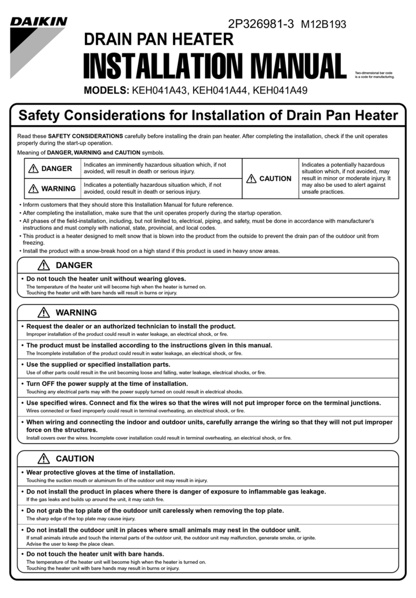
Daikin KEH041A43 User manual

Daikin

Daikin KEH041A43 User manual

Daikin KEH041A41 User manual

Daikin

Daikin KEH041A41 User manual

Daikin Altherma 3 GEO Product information sheet

Daikin

Daikin Altherma 3 GEO Product information sheet

Daikin DRC User manual

Daikin

Daikin DRC User manual

Daikin RDXYQ8T7V1B User manual

Daikin

Daikin RDXYQ8T7V1B User manual

Daikin Altherma 3 GEO EGSAX06UDA9W Product information sheet

Daikin

Daikin Altherma 3 GEO EGSAX06UDA9W Product information sheet

Daikin KEH041A42 User manual

Daikin

Daikin KEH041A42 User manual

Daikin Altherma 3 H HT F User manual

Daikin

Daikin Altherma 3 H HT F User manual

Daikin KEH094A41E User manual

Daikin

Daikin KEH094A41E User manual

Daikin FWXV15AVEB User manual

Daikin

Daikin FWXV15AVEB User manual

Daikin FWXV15AVEB User manual

Daikin

Daikin FWXV15AVEB User manual

Daikin Altherma EKRTCTRL1 User manual

Daikin

Daikin Altherma EKRTCTRL1 User manual

Daikin REYQ8-48PY1B User manual

Daikin

Daikin REYQ8-48PY1B User manual

Daikin KEH067A41E(A) User manual

Daikin

Daikin KEH067A41E(A) User manual

Popular Heater manuals by other brands

Porter-Cable PCXH80KT Operating instructions and owner's manual

Porter-Cable

Porter-Cable PCXH80KT Operating instructions and owner's manual

Dyna-Glo RA18LPDG user manual

Dyna-Glo

Dyna-Glo RA18LPDG user manual

Dimplex PLX050E instruction manual

Dimplex

Dimplex PLX050E instruction manual

EOS Herkules XL S120 installation instructions

EOS

EOS Herkules XL S120 installation instructions

Trebs Comfortheat 99209 manual

Trebs

Trebs Comfortheat 99209 manual

Biddle STYLE2 Series Installation operation & maintenance

Biddle

Biddle STYLE2 Series Installation operation & maintenance

Vermont Castings Non-Catalytic Convection Heater 2477CE Installation and operating manual

Vermont Castings

Vermont Castings Non-Catalytic Convection Heater 2477CE Installation and operating manual

Fagor RA-1505 Instructions for use

Fagor

Fagor RA-1505 Instructions for use

THERMAL FLOW Delta 175 Operating instructions manual

THERMAL FLOW

THERMAL FLOW Delta 175 Operating instructions manual

GET G2CH instructions

GET

GET G2CH instructions

ApenGroup PK Series User, installation, and maintenance manual

ApenGroup

ApenGroup PK Series User, installation, and maintenance manual

oventrop Regucor Series quick start guide

oventrop

oventrop Regucor Series quick start guide

Blaze King CLARITY CL2118.IPI.1 Operation & installation manual

Blaze King

Blaze King CLARITY CL2118.IPI.1 Operation & installation manual

ELMEKO ML 150 Installation and operating manual

ELMEKO

ELMEKO ML 150 Installation and operating manual

BN Thermic 830T instructions

BN Thermic

BN Thermic 830T instructions

KING K Series Installation, operation & maintenance instructions

KING

KING K Series Installation, operation & maintenance instructions

Empire Comfort Systems RH-50-5 Installation instructions and owner's manual

Empire Comfort Systems

Empire Comfort Systems RH-50-5 Installation instructions and owner's manual

Well Straler RC-16B user guide

Well Straler

Well Straler RC-16B user guide

manuals.online logo
manuals.online logoBrands
  • About & Mission
  • Contact us
  • Privacy Policy
  • Terms and Conditions

Copyright 2025 Manuals.Online. All Rights Reserved.

Description
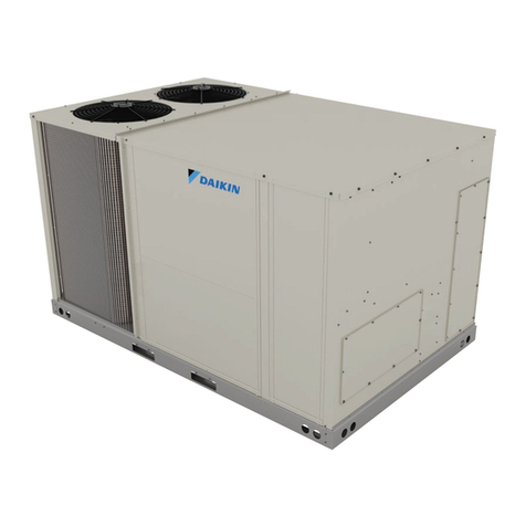
These installation instructions supplement the electric heater kits
for installation in the following models:
DRC036, DRC048, DRC060, DRC072
DRH036, DRH048, DRH060, DRH072
DBC036, DBC048, DBC060, DBC072
DBH036, DBH048, DBH060, DBH072
These instructions should be used only as a supplement to
installation instructions IOD-1032 for DRC and DRH models,
or IOD-1043 for DBC and DBH models. If the heater kit is
installed on a unit with DDC controls, reference the DDC user
manual for controller conguration instructions. The controller
will not control the heater kit unless it is properly congured.
WARNING
HIGH VOLTAGE!
DISCONNECT ALL POWER BEFORE SERVICING OR INSTALLING
THIS UNIT. MULTIPLE POWER SOURCES MAY BE PRESENT. FAILURE
TO DO SO MAY CAUSE PROPERTY DAMAGE, PERSONAL INJURY OR
DEATH.
INSTRUCTIONS
1. Disconnect all power to the unit, both indoor and outdoor.
2. Remove control box door.
3. Remove blower door.
4. Locate heater box. Remove screws holding the heater box cover
in place (Figure 1).
BLOWER DOOR
HEAT BOX
COVER
HORIZONTAL
SUPPLY COVER
Figure 1
Attention Installing Personnel
As a professional installer, you have an obligation to know the prod-
uct better than the customer. This includes all safety precautions
and related items.
Prior to actual installation, thoroughly familiarize yourself with this
Instruction Manual. Pay special attention to all safety warnings.
Often during installation or repair, it is possible to place yourself in a
position which is more hazardous than when the unit is in operation.
Remember, it is your responsibility to install the product safely and to
know it well enough to be able to instruct a customer in its safe use.
Safety is a matter of common sense...a matter of thinking before
acting. Most dealers have a list of specic good safety practices...
follow them.
The precautions listed in this Installation Manual are intended as
supplemental to existing practices. However, if there is a direct
conict between existing practices and the content of this manual,
the precautions listed here take precedence.
SAFETY CONSIDERATIONS
The following symbols and labels are used throughout this manual
to indicate immediate or potential safety hazards. It is the owner’s
and installer’s responsibility to read and comply with all safety
information and instructions accompanying these symbols. Failure
to heed safety information increases the risk of personal injury,
property damage, and/or product damage.
ELECTRIC HEAT KITS EHXD, EHXB,
EHSD AnD EHSB
foR
3-6 Ton LIGHT CoMMERCIALRoof ToP UnITS
MoDELS: DRC, DRH, DBC AnD DBH
InSTALLATIon InSTRUCTIonS
© 2019
19001 Kermier Rd., Waller, TX 77484
www.daikincomfort.com
P/N: IOD-7100A Date: December 2019
O
NLY
PERSONNEL
THAT
HAVE
BEEN
TRAINED
TO
INSTALL
,
ADJUST
,
SERVICE
OR
REPAIR
(
HEREINAFTER
, “
SERVICE
”)
THE
EQUIPMENT
SPECIFIED
IN
THIS
MANUAL
SHOULD
SERVICE
THE
EQUIPMENT
. T
HE
MANUFACTURER
WILL
NOT
BE
RESPONSIBLE
FOR
ANY
INJURY
OR
PROPERTY
DAMAGE
ARISING
FROM
IMPROPER
SERVICE
OR
SERVICE
PROCEDURES
. I
F
YOU
SERVICE
THIS
UNIT
,
YOU
ASSUME
RESPONSIBILITY
FOR
ANY
INJURY
OR
PROPERTY
DAMAGE
WHICH
MAY
RESULT
. I
N
ADDITION
,
IN
JURISDICTIONS
THAT
REQUIRE
ONE
OR
MORE
LICENSES
TO
SERVICE
THE
EQUIPMENT
SPECIFIED
IN
THIS
MANUAL
,
ONLY
LICENSED
PERSONNEL
SHOULD
SERVICE
THE
EQUIPMENT
. I
MPROPER
INSTALLATION
,
ADJUSTMENT
,
SERVICING
OR
REPAIR
OF
THE
EQUIPMENT
SPECIFIED
IN
THIS
MANUAL
,
OR
ATTEMPTING
TO
INSTALL
,
ADJUST
,
SERVICE
OR
REPAIR
THE
EQUIPMENT
SPECIFIED
IN
THIS
MANUAL
WITHOUT
PROPER
TRAINING
MAY
RESULT
IN
PRODUCT
DAMAGE
,
PROPERTY
DAMAGE
,
PERSONAL
INJURY
OR
DEATH
.
WARNING
PROP 65 WARNING
FOR CALIFORNIA CONSUMERS
Cancer and Reproductive Harm -
www.P65Warnings.ca.gov
0140M00517-A
2
ELECTRIC HEATER KIT
ELECTRIC
PANEL PART
HEATING
ELEMENT PART
Figure 2
Wires and some components are not shown
5. Install heating element part of the heater kit (Figure 2) in the
heater box using screws from heater box cover. Ensure the
elements are positioned in the retaining bracket as shown in
Figure 3. It may be necessary to remove the horizontal supply
cover to observe the bracket. The heater box cover can be
discarded.
6. Install electric panel part of the kit to the left side of the heater
box using 3 screws supplied with this IO (Figure 4).
Figure 3
7. Connect power to kit.
• Remove power cable from the box.
• Connect wire leads to the line side of the power block on the
heater kit’s electrical panel. Connect one wire lead per pole.
• Route all leads through the blower deck and into the control box
as shown in Figure 4.
• Connect wire leads to the load side of the power block in the
unit’s control box. Connect one wire lead per pole.
NOTE: Single phase kits will only have 2 lugs (L1 and L2).
Figure 4
8. Locate 9-pin plug in unit.
9. Connect the plug to the mating 9-pin plug attached to heater kit
(Figure 4).
10. For EHSD and EHSB models, verify that the SCR step
controlboard DIP switch settings match the wiring diagram
provided with the heater kit.
11. Install blower door and horizontal supply cover if it was removed.
12. Set up a required airow - CFM for your unit with electic heater by
selecting a proper speed tap. For details see Air Flow Adjustment
chapter in IOD-1032 for DRC and DRH models or in IOD-1043
for DBC and DBG models.
• Refer to Air Flow for Electric Heat table in this document to
identify minimum required CFM for your unit with specic heater
model.
• Refer to Appendix A - Blower Performance Tables for speed tap
selection in IOD-1032 for DRC and DRH models or in IOD-1043
for DBC and DBH models.
13. Close control box door.
14. Reconnect power to the unit.
15. Test unit to ensure it is functioning properly.
3
UNITS
HEATER KIT
MODEL NUMBER
kW
MINIMUM
SCFM
EH**-*S05 5
EH**-*S10 10
EH**-*S15 15
EH**-*S05 5
EH**-*S10 10
EH**-*S15 15
EH**-*S18 18
EH**-*S20 20
EH**-*S05 5
EH**-*S10 10
EH**-*S15 15
EH**-*S18 18
EH**-*S20 20
EH**-*S05 5
EH**-*S10 10
EH**-*S15 15
EH**-*S18 18
EH**-*S20 20
EH**-*S30 30
EH**-*S31 30
1950
AIR FLOW FOR ELECTRIC HEAT
DRC060, DRH060,
DBC060, DBH060
DRC036, DRH036,
DBC036, DBH036
DRC048, DRH048,
DBC048, DBH048
975
1300
1625
DRC072, DRH072,
DBC072, DBH072
EH X D - 3 S 15
1 2 3 - 4 5 6, 7
Electric Heater
Heater Type
XStaged
SSCR (modulating)
Drive System
BBelt Drive
DDirect Drive
Voltage
1208-230/1/60 Single phase 60 Hz
3208-230/3/60
Three phase 60 Hz
4460/3/60
Three phase 60 Hz
7575/3/60
Three phase 60 Hz
Chassis
SSmall
MMedium
LLarge
Kilowatt
55 KW HIGH AND STANDARD STATIC
10
15
18
20
30
31
18 KW HIGH AND STANDARD STATIC
20 KW HIGH AND STANDARD STATIC
30 KW HIGH STATIC
30 KW STANDARD STATIC
HEATER KIT MODEL NUMBER NOMENCLATURE
10 KW HIGH AND STANDARD STATIC
15 KW HIGH AND STANDARD STATIC
4
NOTE: SPECIFICATIONS AND PERFORMANCE DATA LISTED HEREIN ARE SUBJECT TO CHANGE WITHOUT NOTICE
Quality Makes the Difference!
All of our systems are designed and manufactured with the same high quality standards regardless of size or efciency. We have designed
these units to signicantly reduce the most frequent causes of product failure. They are simple to service and forgiving to operate. We use qual-
ity materials and components. Finally, every unit is run tested before it leaves the factory. That’s why we know. . .There’s No Better Quality.
Visit our website at www.daikincomfort.com for information on:
• Products
• Warranties
• Customer Services
• Parts
• Contractor Program and Training
• Financing Options
© 2019
CUSTOMER FEEDBACK
Daikin is very interested in all product comments.
Please ll out the feedback form on the following link:
https://daikincomfort.com/contact-us
You can also scan the QR code on the right to be directed to the feedback page.