5English
CAUTION
After a long use, check the unit stand and fitting
for damage.
If they are left in a damaged condition, the unit may
fall and result in injury.
Do not allow a child to mount on the unit or avoid
placing any object on it.
Falling or tumbling may result in injury.
Do not let children play on and around the unit.
If they touch the unit carelessly, it may result in injury.
Do not place a flower vase and anything contain-
ing water.
Water may enter the unit, causing an electric shock or fire.
Never touch the internal parts of the controller.
Do not remove the front panel. Some parts inside are dan-
gerous to touch, and a machine trouble may happen.
For checking and adjusting the internal parts, contact
your dealer.
Avoid placing the controller in a spot splashed
with water.
Water coming inside the machine may cause an electric
leak or may damage the internal electronic parts.
Do not operate the air conditioner when using a
room fumigation - type insecticide.
Failure to observe could cause the chemicals to become
deposited in the unit, which could endanger the health of
those who are hypersensitive to chemicals.
Safely dispose of the packing materials.
Packing materials, such as nails and other metal or
wooden parts, may cause stabs or other injuries.
Tear apart and throw away plastic packaging bags
so that children will not play with them. If children
play with a plastic bag which was not torn apart, they
face the risk of suffocation.
Do not turn off the power immediately after stop-
ping operation.
Always wait at least five minutes before turning off the
power. Otherwise, water leakage and trouble may occur.
The appliance is not intended for use by young
children or infirm persons without supervision.
The remote controller should be installed in
such away that children cannot play with it.
NOTE
Never press the button of the remote controller
with a hard, pointed object.
The remote controller may be damaged.
Never pull or twist the electric wire of the remote
controller.
It may cause the unit to malfunction.
Do not place the controller exposed to direct sunlight.
The LCD display may get discolored, failing to dis-
play the data.
Do not wipe the controller operation panel with
benzine, thinner, chemical dustcloth, etc.
The panel may get discolored or the coating peeled
off. If it is heavily dirty, soak a cloth in water-diluted
neutral detergent, squeeze it well and wipe the panel
clean. And wipe it with another dry cloth.
Dismantling of the unit, treatment of the refriger-
ant, oil and eventual other parts, should be done
in accordance with the relevant local and
national regulations.
CONTENTS
BEFORE USE ..................................................... 1
GENERAL DESCRIPTION OF SYSTEM .............. 1
SAFETY CONSIDERATIONS ....................... 2
FEATURES AND FUNCTIONS .................... 6
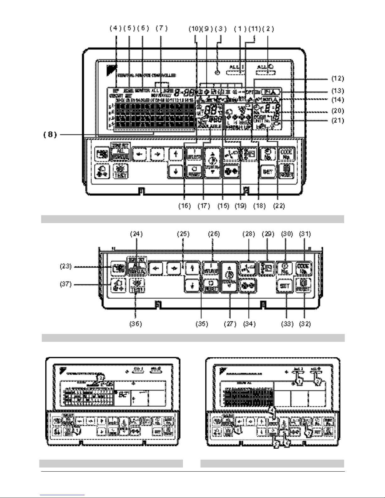
NAMES AND FUNCTIONS OF THE
OPERATING SECTION .................................. 7
OPERATION........................................................ 8
Individual screen, all screen, zone screen ............. 8
Batch operation and stop method ......................... 9
Group operation and stop method.......................... 9
Registering zones................................................... 9
Zone operation and stop method ......................... 10
Changing the fan direction and fan strength ........ 11
Changing the ventilation mode and
ventilation strength .............................................. 11
Timer Number Setting ......................................... 11
Setting the Operation Code.................................. 12
OPERATION MODE ........................................ 13
Setting operation mode .........................................16
Group monitoring ..................................................16
Error diagnosing function .....................................17
Setting master remote controller ..........................20
Display of time to clean .........................................21
INSTALLATION TABLE ................................ 22
OPTIONAL ACCESSORIES......................... 23
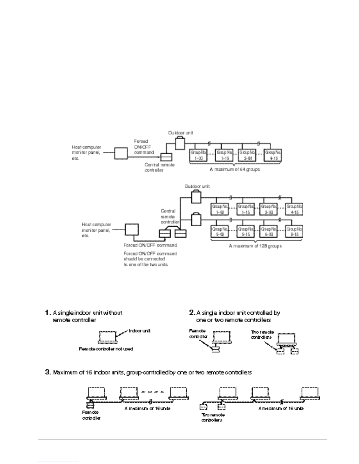
DOUBLE CENTRAL REMOTE
CONTROLLERS ............................................... 23
SPECIFICATIONS............................................ 24
Specifications .......................................................24
Outline drawings ..................................................24
Fig. 1, 2, 3, 4...............................................................3
Fig. 5, 6, 7, 8...............................................................4
Fig. 9, 10, 11, 12.......................................................25
Fig. 13, 14, 15, 16.....................................................26