Daikin BYCQ140D7GW1 User manual

Decoration Panel Provided with Filter Auto Cleaning Function
Self Cleaning decoration panel
INSTALLATION MANUAL
BYCQ140D7GW1
BYCQ140D7GFW1

Installation manual BYCQ140D7GW1 + BYCQ140D7GFW1
Self cleaning decoration panel
4P310441-1C–2017.05
1
BYCQ140D7GW1
BYCQ140D7GFW1 Self cleaning decoration panel Installation manual
Contents
1. SAFETY PRECAUTIONS..........................................................1
2. ACCESSORY ............................................................................1
3. INSTALLATION SITE.................................................................2
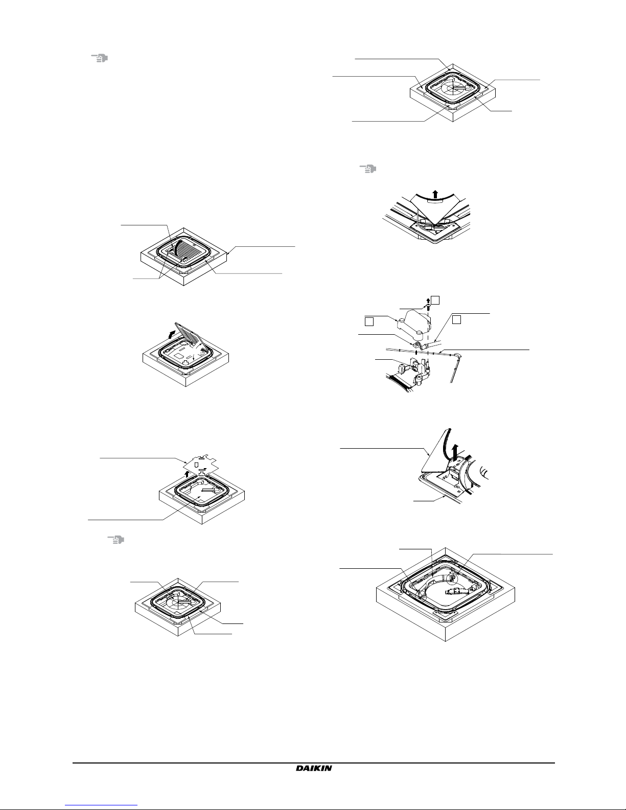
4. PREPARATIONS FOR PANEL..................................................3
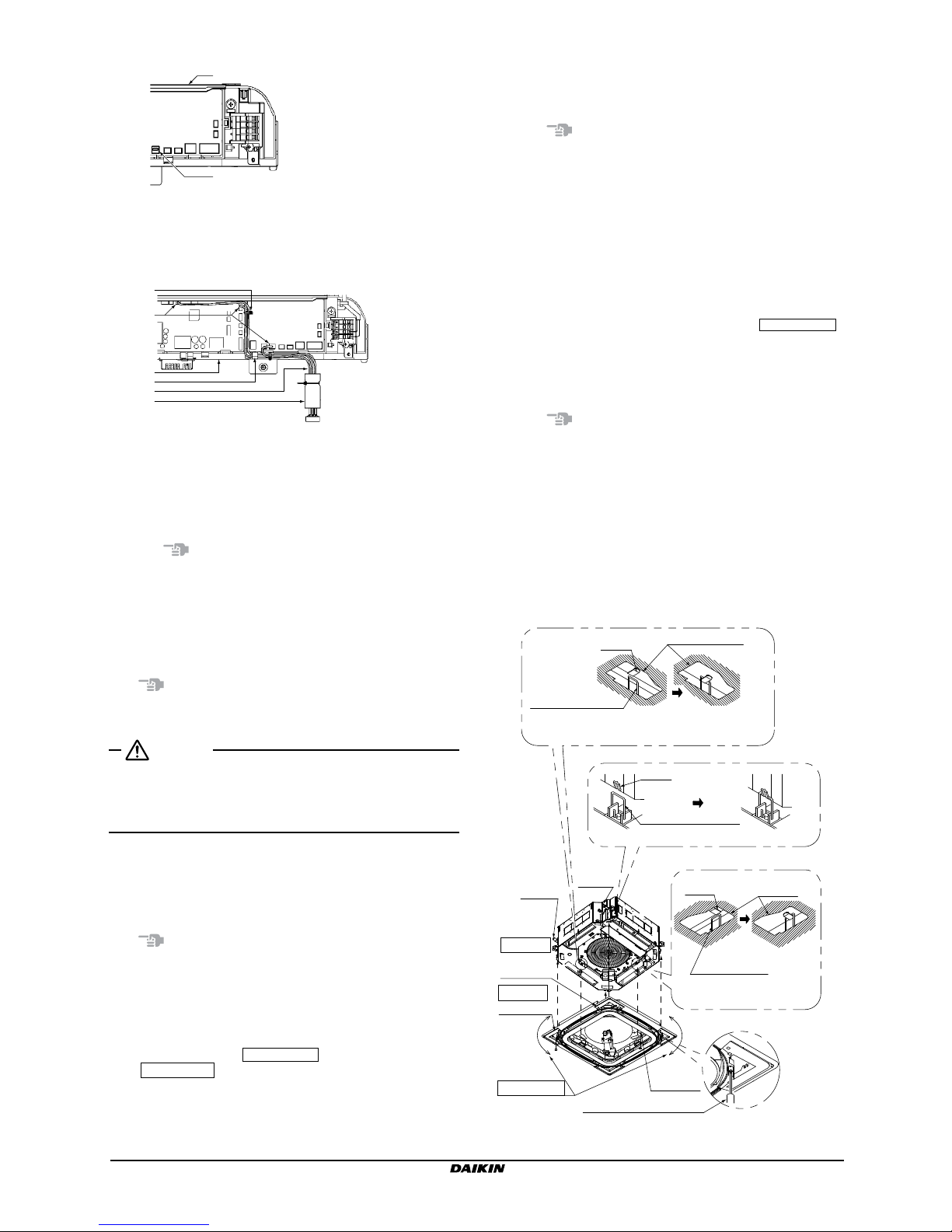
5. PREPARATIONS FOR INDOOR UNIT......................................4
6. ATTACHING PANEL TO INDOOR UNIT....................................5
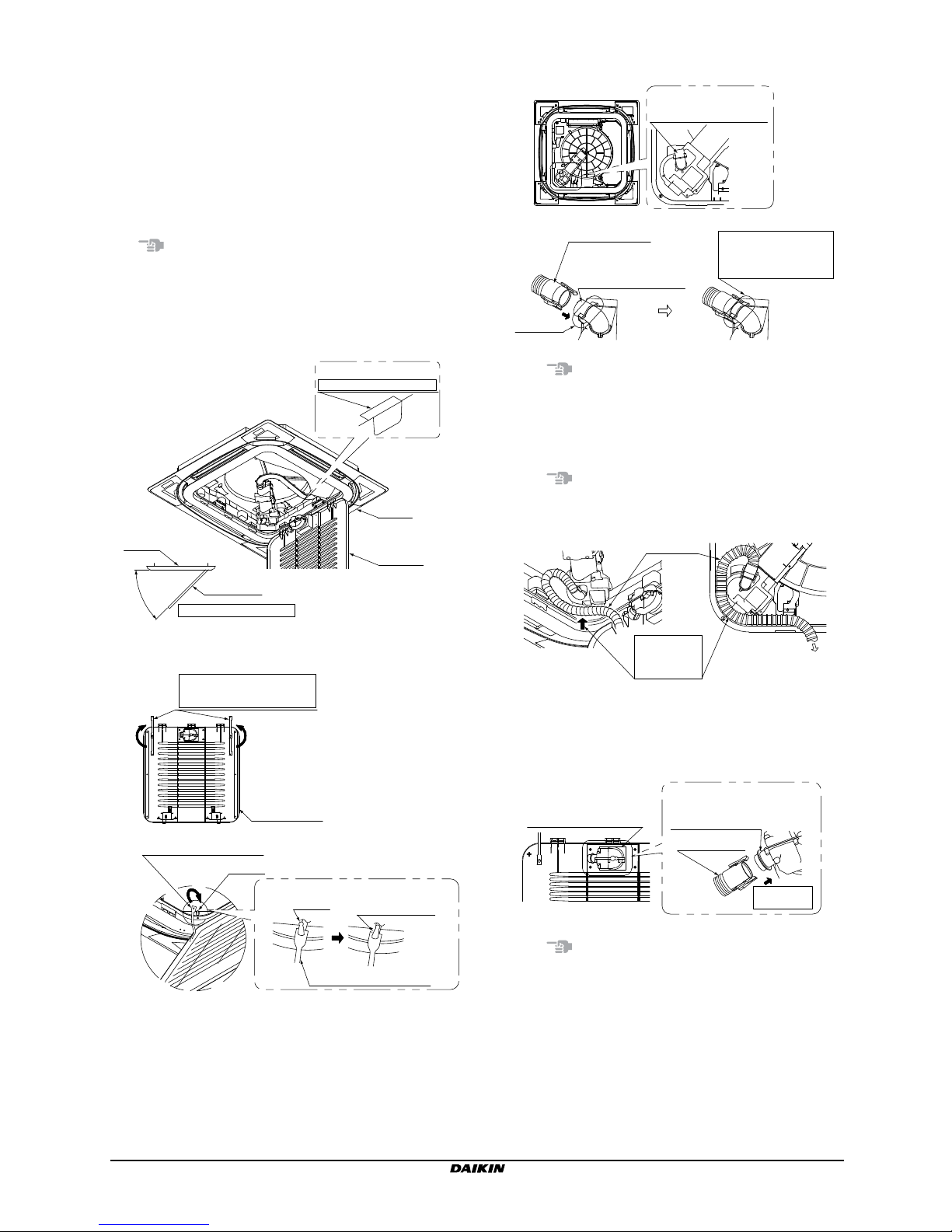
7. ATTACHING SUCTION GRILLE AND DECORATION
CORNER COVERS...................................................................8
8. OPERATION MODE SETTINGS.............................................10
9. FIELD SETTINGS....................................................................10
10. TEST OPERATION..................................................................11
The English text is the original instruction. Other languages are
translations of the original instructions.
1. Safety precautions
Please read these "Safety precautions" carefully before installing air
conditioning equipment and be sure to install it correctly.
After completing installation, conduct a trial operation to check for
faults and explain to the customer how to operate the air
conditioner and take care of it with the aid of the operation manual.
Ask the customer to store the installation manual along with the
operation manual for future reference.
This air conditioner comes under the term "appliances not
accessible to the general public".
Meaning of WARNING and CAUTION notices.
WARNING Failure to follow these instructions properly
may result in personal injury or loss of life.
CAUTION Failure to observe these instructions properly
may result in property damage or personal
injury, which may be serious depending on
the circumstances.
WARNING
• Ask your dealer or qualied personnel to carry out installation
work.
Do not attempt to install the air conditioner yourself. Improper
installation may result in water leakage, electric shocks or re.
• Perform installation work in accordance with the instructions in
this installation manual. Do not modify the product.
Improper installation may result in water leakage, electric shocks,
or re.
• Be sure to use only the specied accessories and parts for
installation work.
Failure to use the specied parts may result in the unit falling,
water leakage, electric shocks or re.
• Make sure that specied wires are used and that there is no
strain on the terminal connections or wires.
Improper connections or securing of wires may result in
abnormal heat radiation or re.
• Be sure to switch off the unit before touching any electrical parts.
• Arrange the lead wires of the provided harness so that the EL.
COMPO. BOX lid of the indoor unit will not rise, and attach the lid
securely.
Heat radiation, electric shocks, or re may result if the EL.
COMPO. BOX lid is not attached properly.
• Tear up and dispose of the plastic bag.
Children playing with the plastic bag may be suffocated.
CAUTION
• Install the indoor and outdoor units, power cord, remote controller
wiring, and transmission wiring at least 1 m away from TV or
radio sets. This is for the prevention of TV and radio interference.
(Depending on the incoming signal strength, a distance of
1 meter may not be sufcient to eliminate noise.)
• Pay the utmost attention to the transportation of the product.
Hold the handles on the package to carry the product.
Do not carry the package with the polypropylene band on the
package held, which will be dangerous because the
polypropylene band may be deformed.
• Do not touch the n of the heat exchanger.
Touching the n improperly may result in injury.
• Do not turn the product power off immediately after the operation
of the product comes to a stop.
Always wait for at least 5 minutes before turning the product
power off.
Otherwise, water leakage and malfunctions may result.
• Do not install the air conditioner in the following locations:
1. Where there is a high concentration of mineral oil spray or
vapour (e.g. a kitchen).
Plastic parts will deteriorate, parts may fall off and water
leakage could result.
2. Where corrosive gas, such as sulphurous acid gas, is
produced.
Corroding of copper pipes or soldered parts may result in
refrigerant leakage.
3. Near machinery emitting electromagnetic radiation.
Electromagnetic radiation may disturb the operation of the
control system and result in a malfunction of the unit.
4. Where ammable gas may leak, where there is carbon bre or
ignitable dust suspensions in the air, or where volatile
ammables such as paint thinner or gasoline are handled.
Operating the unit in such conditions may result in re.
[Instructions peculiar to this product]
Do not install the product in the following places.
Oil, cigarette tar, and steam will result in sticky dust on the lter,
which may not be cleaned properly. Furthermore, sticky dust may
cause malfunctions.
Places with oily smoke: Restaurants, factories, etc.
Places with excessive cigarette smoke: Smoking room, etc.
Places with excessive moisture or steam: Restaurants, factories,
etc.
• The air conditioner is not intended for use in a potentially
explosive atmosphere.
Note
• Have the customer actually operate the air conditioner while
referring to the operation manual and explain the right operation
of the air conditioner with useful tips given.
• Refer to the operation manual along with the installation manual
provided with the indoor unit.
• Use the BRC1E51A7 remote controller.
2. Accessory
Check that the following accessories provided with the air
conditioner are correct in number. See the following illustration,
which shows where the accessories are kept.
Backside of the protective
corrugated cardboard
A set of accessories
The accessories are
on the backside of the
protective corrugated
cardboard under
the suction grille.
Suction grille

BYCQ140D7GW1 + BYCQ140D7GFW1 Installation manual
Self cleaning decoration panel
4P310441-1C–2017.05 2
Name Spacer
(1)
Flexible
hose (2)
S-shaped
pipe (3) Harness (4)
Clamp
(5)
Quantity 1 pc. 1 pc. 1 pc. 1 pc. 2 pc.
Shape
Name Connecting
pipe (6)
Attachment
(7) Seal (8)
OthersQuantity 1 pc. 1 pc. 1 pc.
Shape
• Operation
manual
• Installation
manual
Pay the utmost attention to the following items when
conducting installation work, and recheck the items on
completion of the work.
a. Test items on completion of work
Test items In case of failure Result
Is the air conditioner free of wiring and
connection mistakes or omissions? Operation failure
and wire burnout
Are you sure that there is no space
between the ceiling and ceiling material?
Water leakage
Are the xing knobs (in two points) of
the dust box secured tightly?
Vibration, noise,
and dust
collection failure
Are the xed knobs (in ve points) of
the air lter secured tightly?
Vibration, noise,
and dust
collection failure
Is the fall prevention cord for the dust
box and grille hooked to the mounting
bracket? Fall
Did you attach the EL. COMPO. BOX
lid, dust box, exible hose, S-shaped
pipe, suction grille, and decoration
corner covers?
Noise and dust
collection failure
* Be sure to recheck the items provided in the section "1. Safety
precautions" on page 1.
b. Test items before delivery
Test items Result
Was the test operation of the air conditioner nished?
Did you explain the operation method of the air
conditioner to the customer while showing the customer
the operation manual? *
Did you make mode settings for lter auto cleaning
(automatic control operation settings or timer operation
settings with an operation time zone specied) and
provide information on the set mode operation of the air
conditioner to the customer?
Did you deliver the operation manual to the customer?
(Be sure to hand the customer the operation manual as
well as the installation manual.)
Did you hand the customer the connecting pipe and
attachment and ask the customer to keep them?
* Point of operation explanation
In addition to the general usage of the air conditioner, it is
necessary to explain the descriptions of the WARNING and
CAUTION marked items in the operation manual and have
the customer read the descriptions carefully, because these
items indicate information that, if not heeded, is likely to result in
loss of life, serious injury, or property damage.
3. Installation site
This product offers selectable air outlet directions. A closure kit (an
optional accessory) is required to achieve three-way ow patterns.
Two-way ow patterns are not available to this product.
3-1 Select the installation site that meets the
following conditions with the consent of the
customer
• The surface of the ceiling is not remarkably inclined.
• Installation and service workspace is secured (see the following
illustrations).
• The panel indicators are seen with ease.
• The indoor and outdoor units, power cord, transmission wiring,
and remote controller wiring are at least 1 m away from TV or
radio sets.
(The above is for the prevention of TV and radio interference.
Depending on the incoming signal strength, a distance of 1 meter
may not be sufcient to eliminate noise.)
3-2 Required installation space
Install the indoor unit according to the installation manual and the
following illustrations.
Indicator
Dust collection inlet
Front side of panel
1 2
3
10°
10°
256
4
5
1 Indoor unit
2 Drain socket
3 At least 1500 mm away from the wall. This space will be
at least 500 mm with the air outlet closed and blocking
pad installed.
4 Dust collection inlet
5 A space is required for dust collection with a vacuum
cleaner used
3-3 Mounting directions of suction grille
Select one of the following mounting directions of the suction grille
on the panel.
Piping
Piping
Drain
socket
Dust
collection
inlet
Drain
socket
Suction
grille

Installation manual BYCQ140D7GW1 + BYCQ140D7GFW1
Self cleaning decoration panel
4P310441-1C–2017.05
3
4. Preparations for panel
Note
• Perform all the required work in "4. Preparations for panel" on
page 3 with the panel kept in the packing material (on the
bottom side).
• Do not put the panel downward or upright or leave the panel on
protruding parts.
Otherwise, scratch damage to the surface of the panel may
result.
• Do not touch the swing ap and do not put any force on the
swing ap. This will result in malfunction of the unit.
4-1
Removal of suction grille from panel,
protective corrugated cardboard, and set of
accessories
(1) Press the knobs of the suction grille and lift up the knobs.
Decoration panel
Knobs
Packing material
(bottom)
Suction grille
(2) Open the suction grille to an angle of approximately 45° and
remove the suction grille from the panel.
45°
(3) Take out the protective corrugated cardboard.
Take out the protective corrugated cardboard (on top of the
panel) together with the accessories attached to the backside
of the protective corrugated cardboard.
Protective corrugated
cardboard (top)
(The accessories are
on the backside.)
Protective corrugated
cardboard (bottom)
Note
Do not impose force on the swing ap, brush unit, or air lter
when handling the panel.
Panel
Brush unit
Air filter
Swing flap
4-2 Removal of decoration corner covers
Panel
Decoration corner cover
Decoration
corner cover
Decoration corner
cover (with display)
(1) Raise and remove the decoration corner cover (with the
display) in the direction of the arrow.
Note
Do not impose force on the lead wires.
Operation/filter cleaning
(2) Remove the screws on the backside of the decoration corner
cover (with the display), open the cover, and remove the
connector attached to the front end of the lead wires from the
PCB.
Cover
Connector
Lead wires
PCB
3
1
Screw
2
Decoration corner cover
(with display)
(3) Remove each of the remaining decoration corner covers (i.e.,
three covers) in the direction of the arrow.
Panel
Decoration corner cover
4-3 Removal of dust box
Fixing knob
of dust box
and clasp
Dust box Fixing knob of dust box

BYCQ140D7GW1 + BYCQ140D7GFW1 Installation manual
Self cleaning decoration panel
4P310441-1C–2017.05 4
(1) Turn the two xing knobs of the dust box.
Dust box
(The front side of the panel is shown for ease of explanation.)
Fixing knob
Fixing knob
(2) Remove the dust box from the panel while paying attention not
to cut the fall prevention cord.
Dust box
Fall prevention cord 2
1
(3) Remove the fall prevention cord for the dust box from the
clasp bracket of the panel.
Remove the fall
prevention cord from
the clasp bracket.
Clasp
Dust box
Fall prevention cord
Panel
5. Preparations for indoor unit
WARNING
Check that the indoor and outdoor units are turned power off
before conducting wiring work.
Otherwise, an electric shock may be received.
CAUTION
• Conduct the following work after installing the indoor unit.
• Install the indoor unit according to the installation manual
provided with the indoor unit.
5-1 Attaching spacer (accessory (1))
(1) Remove the bypass hole closing cap.
12
1 Indoor unit
2 Remove the bypass hole closing cap
(2) Peel off the release paper of the double-stick tape on the
backside of the spacer (accessory (1)).
(3) Attach the spacer (accessory (1)) on the air bypass hole.
Check that the air bypass hole is not blocked after the spacer
is attached.
1
4
2
4
3
1 Air bypass hole
2 Pasted to align with the air bypass hole
3 Align the corners
4 Spacer (accessory (1))
5-2 Attaching harness (accessory (4))
(1) Remove the EL. COMPO. BOX lid from the indoor unit.
Claws
EL. COMPO. BOX lid
Screws
(2 points)
Loosen the screws (in two points) and slide the EL. COMPO. BOX
lid in the direction of the arrow to unhook the lid from the claws.

Installation manual BYCQ140D7GW1 + BYCQ140D7GFW1
Self cleaning decoration panel
4P310441-1C–2017.05
5
(2) Remove jumper connector from X8A.
1
2
X8A
1 EL. COMPO. BOX
2 Jumper connector
(3) Connect the harness (accessory (4)) to the connectors (X8A,
X35A and X36A) and the three points of the harness on the
unit side.
6
5
1
2
3
4
X35A X36A
X8A
X35A X36A
1 Harness on the unit side
2 Connector
Be sure to connect them securely
3 EL. COMPO. BOX
4 Hook X35A, X36A
5 Harness (accessory (4))
6 Glass tube
Note
Make sure that the connectors are securely connected, or
otherwise the swing ap, brush unit, or air lter will not work.
5-3 Attaching EL. COMPO. BOX lid
Attach the EL. COMPO. BOX lid in the order opposite to the
procedure in "5-2 Attaching harness (accessory (4))" on page 4
(1).
Note
Make sure that the wires or glass tube will not be caught by the EL.
COMPO. BOX lid.
WARNING
Arrange the electric wires neatly and attach the EL. COMPO.
BOX lid securely.
The electric wires being caught or the rising of the EL. COMPO.
BOX lid may result in an electric shock or re.
6. Attaching panel to indoor unit
Install the indoor unit by referring to the installation manual
provided with the indoor unit.
Note
Do not impose force on the swing ap, brush unit, or air lter when
taking out the panel from the packing material (on the bottom side).
6-1 Checks before attaching panel
• Check the directions of the indoor unit and the engraved marks
on the panel as shown below.
The piping block to the PIPING SIDE and the drain socket to
the DRAIN SIDE .
• Stand the temporary latching bracket upright.
• Draw out the lead wires (on the panel side) from the opening.
6-2 Attaching panel
(1) Tentatively put the two temporary latching brackets of the
suction port of the panel (on the internal circumference side) to
the hooks of the indoor unit.
Note
Leave your hands after conrming through the check window
that the temporary latching brackets are engaged with the
hooks.
(2) Draw out from the opening the harness attached in "5.
Preparations for indoor unit" on page 4.
Furthermore, pull out the lead wires disconnected from the
corner decoration cover (with the display) in "4. Preparations
for panel" on page 3 from the corner hole carefully so that
the lead wires will not be caught by the mounting bracket.
(3) Put the mounting brackets (in four points) on the corners of the
panel to the hooks of the circumference of the indoor unit.
(Hook the mounting bracket engraved with the PIPING SIDE
rst, followed by the mounting bracket on the opposite angle
side.)
At that time, pay attention that the harness and lead wires (on
the panel side) will not be caught between the panel and
indoor unit.
Note
Leave your hands after conrming that the mounting brackets
are engaged with the hooks.
(4) Tighten the four hexagon head screws right under the
mounting bracket for approximately 5 mm. (The panel will
move upward.)
(5) Turn the panel in the directions of the arrows so that the
opening on the ceiling will be perfectly covered by the panel.
(6) Furthermore, tighten the screw (4) until the distance from the
lower part of the hook of the indoor unit to the lower part of the
panel becomes 107 to 112 mm.
Drain
socket Piping
Hook
Mounting bracket
6-2 (3)
6-2 (1)
6-2 (5)
6-2 (4)
6-2 (6)
Before temporarily
hooking After temporarily
hooking
Temporary
latching brackets
Check window
Hook
(4 points)
Before hooking After hooking
6-2 (1)
Hook Check
window
Temporary
latching brackets
Before temporarily
hooking After temporarily
hooking
PIPING SIDE
engraved
mark
DRAIN SIDE
engraved mark
Make adjustments
Opening
Tool (e.g., screwdriver)

BYCQ140D7GW1 + BYCQ140D7GFW1 Installation manual
Self cleaning decoration panel
4P310441-1C–2017.05 6
107~112mm
6-2
(6)
Panel
Lower side
of panel
Indoor unit
Lower part of hook of
the indoor unit
(The ceiling is
omitted from the
illustration for ease
of explanation)
107~112mm
Seal Indoor unit
Lower part of
hook of the
indoor unit
Ceiling
Mounting bracket
Lower side of panel
Panel
Cross sections (4 points)
Note
• Tighten the screws securely, or otherwise a defect as shown
below may result.
• Readjust the height of the indoor unit if there is a space between
the ceiling and panel with the screws tightened securely.
Air
leakage
Air leakage
from the
ceiling side.
Generation
of dirt Drew condensation
or dripping
Make sure that there is no space.
Height adjustments to the unit
will be possible through the
holes on the corners of the
panels without removing the
panel, provided that the
adjustments does not affect the
levelness or the drain piping of
the indoor unit. Refer to the
installation manual of the indoor
unit to conduct the work.
6-3 Checking panel
(1) Remove sealing of panel.
1 2 1
2
3
4
1 Remove seal of panel
2 Insert the seal until the seal comes in contact with the
claw
3 Claw
4 Sealing (accessory (8))
(2) Draw the harness and lead wires (on the panel side).
Panel
Harness
Harness
Lead wire
(on the panel side)
Lead wire
(on the panel side)
(3) Connect the connector of the lead wires and move the glass
tube to cover the connector part.
Lead wire
(on the panel side)
Harness
Connector
Be sure to connect
them securely.
Move the
glass tube.
1
2
Glass tube
(4) Tighten and secure both ends of the glass tube with the
clamps on the glass tube together with provided clamps
(accessories (5)). Cut the redundant portions of the clamps
from their roots after the both ends are secured.
Tighten the clamps
Cut the roots
Clamp
(accessory (5))
(5) Return the connected lead wires to the space between the
indoor unit and panel.
(Accommodate the lead wires in the shaded part shown in the
illustration.)
Note
Accommodate the lead wires carefully so that the lead wires
will not come in contact with the air lter.
Connected
lead wires
Connected
lead wires
Panel
EL. COMPO. BOX
of the indoor unit

Installation manual BYCQ140D7GW1 + BYCQ140D7GFW1
Self cleaning decoration panel
4P310441-1C–2017.05
7
(6) Remove the EL. COMP. BOX lid from the indoor unit.
Refer to "5-2 Attaching harness (accessory (4))" on page 4.
(7) Connect the swing lead wire connector to the PCB.
2
1
3
X9A
1 PCB
2 Connect the swing lead wire connector to the PCB
Be sure to connect them securely.
3 Swing lead wire (to X9A)
(8) Attach the EL. COMP. BOX lid in the order opposite to the
procedure in "5-2 Attaching harness (accessory (4))" on
page 4.
(9) Guide the lead wires through the hook.
21
1 Hook
2 Guide the wires through the hook
6-4 Attaching dust box
1
2
3
45
6
7
b
a
1 Engraved mark on piping side
2 Panel clasp
3 Engraved mark on drain side
4 Panel
5 Fall prevention cord
6 Dust box
7 Mount the dust box with the side where the mark is
engraved faced downward.
(1) Hook the fall prevention cord for the dust box to the panel
clasp as shown in the illustration.
1
2
3
4
5
1 Clasp
2 Hooked fall prevention cord
3 Panel
4 Fall prevention cord
5 Dust box
(2) Attach the dust box in the order opposite to the procedure in
"4-3 Removal of dust box" on page 3.
Note
Make sure that the fall prevention cord is not caught by the
exhaust opening on the dust box when attaching the dust box.
Otherwise, the dust box may not function normally.
(3) Turn the xing knobs (in two points) of the dust box and secure
the dust box.
(The front side of the panel is shown
for ease of explanation.)
Fixing
knob
Fixing
knob
6-5 Mounting S-shaped pipe (accessory (3))
Mount the dust box side (engraved with A) before mounting the
brush side (engraved with B).
(Mount them so that the engraved characters will be in conformity.)
Dust box
Dust box
Brush unit
Make sure that
the engraved
characters are in
conformity with
each other.
2
Claws
(2 points)
Claw
(1 point)
Brush unit
Brush unit side
S-shaped pipe
(accessory (3))
Dust box side
Make sure that the
engraved characters
are in conformity with
each other.
1
Note
Check that the claws are engaged securely. Otherwise, a dust
collection failure may result.

BYCQ140D7GW1 + BYCQ140D7GFW1 Installation manual
Self cleaning decoration panel
4P310441-1C–2017.05 8
7. Attaching suction grille and
decoration corner covers
The suction grill can be rotated and attached in two directions,
either one of which is selectable.
If a number of units are installed, adjust the directions of the suction
grilles if necessary. Make directional changes as well at the request
of the customer.
7-1 Attaching suction grille
* Select either the hook (A) or (B), and hook the claws of the
suction grille.
Note
The suction grille may be damaged if the wrong hooking side is
selected.
7-2 Hook (A)
(1) Set the suction grille to an angle of approximately 45° and put
the hooks (in three points) onto the panel.
45°
Panel
Panel
Suction
grille
Suction
grille
SUCTION GRILLE HOOKING SIDE
Suction grille mounting angle
Display on
SUCTION GRILLE HOOKING SIDE
(2) As shown in the illustration, hook the fall prevention cords for
the suction grille to the corner clasps (on two corners).
Change the directions of
the fall prevention cords.
Suction grille
Clasp
Fall prevention cord
Clasp Bend the
clasp inward.
Fall prevention cord
(3)
Connect the exible hose (accessory (2)) onto the panel side.
(The exible hose (accessory (2)) has no directionality constraint.)
Flexible hose junction
on the panel side
Flexible hose
(accessory (2))
Flexible hose junction
on the panel side
Fit the claws into the
hooks (in two points)
securely.
Hooks
(2 points)
Note
Check that the claws are engaged securely. Otherwise, a dust
collection failure may result.
(4) Press t the exible hose connected in (3) into the panel.
(Pay attention so that the hose will not be caught by the
suction grille closed.)
Note
Be sure not to break the exible hose when press tting the
exible hose.
Flexible
hose
To suction grille
Press fit the
flexible hose
along the shape
of the corner.
(5) Connect the opposite end of the exible hose connected in (3)
onto the suction grille side.
* Rotate the exible hose joint on the suction grille side
according to the mounting direction of the suction grille as
shown in the illustration.
Flexible hose joint on
the suction grille side
Flexible hose
joint on the
suction grille side
Flexible hose
Connect the
hose securely.
Note
Check that the claws are engaged securely. Otherwise, a dust
collection failure may result.

Installation manual BYCQ140D7GW1 + BYCQ140D7GFW1
Self cleaning decoration panel
4P310441-1C–2017.05
9
(6) Push up the suction grille slowly rst, and while pressing the
two knobs, nally t the grille into the panel securely.
Panel
Knobs
(2 points)
Suction grille
Note
The suction grille can catch the fall prevention cords while the
suction grill is closed.
Check that the fall prevention cords do not protrude from the
suction grille before closing the suction grille.
Suction grille
Must not protrude
Fall prevention
cord
7-3 Hook (B)
(1) Set the suction grille to an angle of approximately 45° and put
the hooks (in three points) onto the panel.
45°
Panel
Suction
grille
Suction grille
Panel
Suction grille
mounting angle
SUCTION GRILLE HOOKING SIDE
Display on
SUCTION GRILLE HOOKING SIDE
(2) As shown in the illustration, hook the fall prevention cords for
the suction grille to the corner clasps (on two corners).
Change the directions of the
fall prevention cords.
Suction grille
Clasp
Fall prevention cord
Clasp Bend the
clasp inward.
Fall prevention cord
(3) Connect the exible hose (accessory (2)) onto the panel side.
(The exible hose (accessory (2)) has no directionality
constraint.)
Flexible hose junction
on the panel side
Fit the claws into the
hooks (in two points)
securely.
Flexible hose
(accessory (2))
Flexible hose junction
on the panel side
Hooks
(2 points)
Note
Check that the claws are engaged securely. Otherwise, a dust
collection failure may result.
(4) Press t the exible hose connected in (3) into the panel.
Pay attention so that the hose will not be caught by the suction
grille closed.
Flexible
hose
To suction grille
Press fit the
flexible hose
along the shape
of the corner.
(5) Connect the opposite end of the exible hose connected in (3)
onto the suction grille side.
* Rotate the exible hose joint on the suction grille side
according to the mounting direction of the suction grille as
shown in the illustration.
Flexible hose joint on
the suction grille side
Connect the
hose securely.
Flexible hose
joint on the
suction grille side
Flexible hose
Note
Check that the claws are engaged securely. Otherwise, a dust
collection failure may result.
(6) Push up the suction grille slowly rst, and while pressing the
two knobs, nally t the grille into the panel securely.
Panel
Knobs
(2 points)
Suction grille

BYCQ140D7GW1 + BYCQ140D7GFW1 Installation manual
Self cleaning decoration panel
4P310441-1C–2017.05 10
Note
The suction grille can catch the fall prevention cords while the
suction grill is closed.
Check that the fall prevention cords do not protrude from the
suction grille before closing the suction grille.
Suction grille
Must not protrude
Fall prevention
cord
7-4 Attaching decoration corner covers
(1) Connect the decoration corner cover (with the display)
securely to the PCB in the order opposite to the procedure in
"4. Preparations for panel" on page 3.
2Cover
3Screw
1
Lead
wires
Connector
Connect the
connector
securely.
PCB
Decoration corner
cover (with display)
Clamp
Arrange the lead wires
neatly so that the clamp
will be on the inner side
of the cover.
(2) Attach the decoration corner cover (with the display) to the
corner with the DRAIN SIDE engraved mark. Push the
connected lead wires through the corner hole onto the
backside of the ceiling.
Press fit the five claws on the
decoration corner cover into
the holes on the panel.
Decoration corner
cover (with display)
Lead wires
DRAIN SIDE
engraved mark
(3) Hook each of the cords of the remaining decoration corner
covers (i.e., three covers) onto the corresponding pin on the
panel.
Pin
(4) Attach the decoration corner covers (i.e., the three covers) to
the panel.
Press fit the five claws on the decoration
corner cover into the holes on the panel.
8. Operation mode settings
Any one of the following operation modes can be selected for the
lter auto cleaning of the self-clean panel.
Operation mode Description
(1) Scheduled
timer operation
Performs lter auto cleaning during the
designated period selected from eight periods.
(2) 00:00-to-03:00
operation
Performs lter auto cleaning during the
factory-set period of time (00:00 to 03:00).
(3) Auto control
operation
Performs lter auto cleaning according to the
control reference.
In consultation with the customer, set the desired operation mode
by referring to the instructions on Filter Auto Clean in the operation
manual for the Self Cleaning decoration panel.
At the time of delivery, refer to the contents of descriptions (1)
through (3) in the above table and explain the customer when lter
auto cleaning will start.
9. Field settings
Make settings in consultation with the customer according to the
installation and usage conditions of the air conditioner. The
following four settings are possible.
9-1 Display dust collection
Make settings in order to or not to display the dust collection sign.
9-2 Dust quantity settings
Make settings according to the quantity of dust/size of dust particles
in the room, e.g. stores dealing in clothing=small dust particles.
9-3 Panel indicator (green) On/Off
The panel indicator (green) can display the following operating
conditions. Make indicator settings according to the request of the
customer.
Indicator Operating conditions Remarks
Green
Lit Air-conditioning
operation The indicator is turned
off before shipping.
Flashing Filter auto cleaning
The red lamp to inform the customer of the time of dust collection
will not be turned off.
9-4 Fix cleaning interval
Make settings in order to x the cleaning interval, independent from
the remocon setting.

Installation manual BYCQ140D7GW1 + BYCQ140D7GFW1
Self cleaning decoration panel
4P310441-1C–2017.05
11
Make eld settings according to the installation manual of the
remote controller. (Settings in bold cells are made before shipping.)
Setting
item
Mode
No.
First
code
Second code No.
01 02 03 04 05 06
Display
Dust
Collection
sign 1
10
(20) (3) Display No display – – – –
Dust
quantity
settings
(1)
14
(24) (9)
Standard
quantity of
dust - average
size particles
Large quantity
of
dust - average
size particles
Standard
quantity of
dust - small
size particles
Large
quantity of
dust
- small size
particles
– –
Panel
indicator
(green)
on/off
14
(24) (4)
On while in
air-conditioning
operation and
lter cleaning
operation.
Possible to
turn on while
in lter
cleaning
operation only.
Off while in
air-
conditioning
operation and
lter cleaning
operation.
– – –
Fix
automatic
cleaning
(2)
14
(24) (8)
ON
24h
OFF
ON
12h
ON
48h ON
96h ON
168h
(1) Valid from the next cleaning after the setting is made.
(2) Overrules the time span setting on the remote controller.
10.Test operation
Perform the test operation of the Self Cleaning decoration panel
after the test operation of the indoor unit is nished.
The test operation of the Self Cleaning decoration panel is not
possible while the indoor unit is in operation.
Note
Perform the test operation of the product after referring to "a. Test
items on completion of work".
10-1 Check that the EL. COMPO. BOX lids of the
indoor unit, outdoor unit, and self-clean
panel, respectively, are closed
10-2 Turn the indoor unit power on
The panel will go into initialization operation after the power is
turned on.
10-3 Conduct the test operation of the panel two
minutes after the power is turned on
Conrm the cleaning operation of the lter with the remote
controller.
Test operation method with remote controller
1. Stop the operation of the panel if the panel is in air-conditioning
operation.
2. Continue pressing the Cancel button at least 4 seconds while the
backlight is lit. The service settings menu will appear.
3. Select Test Filter Auto Clean from the service settings menu,
and press the Menu/Enter button.
4. " " will appear on the basic screen.
The display will disappear when the test operation is nished.
The required test operation time is approximately 10 minutes (in
the case of setting the standard quantity of dust).
1.
2. Cool
Set to
Cool
28°C Press and hold
Cancel button for
4 seconds or
longer during
backlight lit.
3.
Return Setting
Service Settings
Indoor Unit Status
Outdoor Unit Status
Forced Fan ON
Switch Main Sub Controller
Filter Indicator OFF
Test Filter Auto Clean
2/3
Press Menu/Enter
button.
4.
Cool
Set to
Cool
28°C
Collect dust
Backlight for LCD
Press any button and the backlight will be lit for approximately
30 seconds.
Perform the operation of buttons while the backlight is lit (except
the On/Off button).
Test items on test operation
Test items Remedy Check
result
Is the lter rotating? Check the
connector
connections.
Are the aps xed horizontally?
Is " " displayed on the screen of
the remote controller?
* The remote controller will display "AH" if the self-clean panel has
an error.
Note
After the test operation of the product is nished, refer to "b. Test
items before delivery" in the installation manual.


Copyright 2012 Daikin
4P310441-1C 2017.05
This manual suits for next models
1
Table of contents
Other Daikin Water Filtration System manuals
Popular Water Filtration System manuals by other brands

VGE
VGE Blue Lagoon PRO UV-C 75W manual

TAISEI KOGYO
TAISEI KOGYO TM instruction manual

Grunbeck
Grunbeck GENO-Baktox MRX Operation manual

Antunes Filtration Technologies
Antunes Filtration Technologies UF-420/440 owner's manual

3M
3M Aqua-Pure AP1610SS manual

PRINCESS HOUSE
PRINCESS HOUSE VADA SANA Installation, Care and Use Manual