manuals.online logo
Brands
  1. Home
  2. •
  3. Brands
  4. •
  5. DAITEM
  6. •
  7. Transmitter
  8. •
  9. DAITEM 230-21X User manual

DAITEM 230-21X User manual

132
GB
Contents
1. Introduction ........................................ 133
2. Preparation ......................................... 136
3. Default configuration......................... 137
4. Programming...................................... 137
5. Advanced configuration operations 139
6. Connection.......................................... 144
7. Installation........................................... 146
8. Operating test..................................... 153
9. Maintenance....................................... 155
10. Technical data .................................. 157
Recommendations
The user must not attempt to access the siren’s internal parts, except areas described in
this manual. If the user does access these parts, the product guarantee will be considered
null and void and DAIT M shall not be held responsible for any problems. Touching the
siren’s internal parts and/or electronic components can damage the product. Furthermore,
the siren is designed in such a way that these parts and components do not need to be
accessed for operation or maintenance purposes.
Non-contractual document, may be modified without
prior notice.
DECLARATION OF CONFORMITY
Manufacturer: Hager Security SAS
Address: F-38926 Crolles Cedex - France
Product type: External universal transmitter
Trade mark: Daitem
We declare under our sole responsibility that the products
to which this declaration relates are thus compliant with
the essential requirements of the following uropean
Directives:
• R&TTE Directive: 99/5/CE
• EMC Directive: 89/336/CEE
• Low Voltage Directive: 73/23/CE
in compliance with the following harmonised uropean
Standards:
These products can be used in all U, A Countries
and Switzerland.
Crolles 02.04.2013
Signature:
Patrick Bernard, Research
& Development Manager
13
GB
Products code 230-21X
EN 300 220-3 X
EN 50130-4 X
EN 60950 X
133
GB
1. Introduction
The external universal
transmitter is fitted with:
• a terminal block n° 1, for
connecting NC or NO
type external intrusion
contacts or command
contacts for system
control,
• a terminal block n° 2, for
connecting a Daitem
technical probe,
• an internal test button,
• an internal test L D
indicator lamp.
IMPORTANT: the two terminal blocks cannot be used at the same time.
IMPORTANT
• Some functions are only available with versions 2.0.0 or later
(press on the control panel keypad to check the version).
• The operating differences with former ranges are described in the compatibility booklet
available in the Daitem installers section at www.daitem.co.uk.
Anti-tamper
protection
against opening
L D
indicator
lamp
Test button Terminal block n° 1
Terminal block n° 2
Cable
gland
Applications Terminal block to be used
Intrusion detection n° 1
Fire detection n° 1
Technical detection n° 2 (specific to Daitem technical probes)
System control n° 1
230-21X
230-21X
134
GB
1.1 Intrusion and fire detector type
applications: terminal block n° 1
• Door and window detector: using a
normally closed contact (surface
mounted, flush-mounted, wide gap, etc.).
• Roller blind/shutter detector: using a
specific contact for roller blinds/security
shutters.
• lassbreak detector: using a piezo-
electric type glassbreak sensor.
• Motion detector: using a motion sensor
(technology: passive infrared, active
infrared, microwave, etc.)
• Pressure mat.
• Fire detector: using a fire sensor.
1.2 System control type
applications: terminal block n° 1
• Automatic ON/OFF (arming/disarming)
transmitter using a programmable time
clock with voltage free output contacts.
• ON/OFF (arming/disarming) transmitter
using a key switch.
• Panic alarm or silent alarm transmitter
using a contact.
• Fire alarm transmitter using a breakglass
type call point.
1.3 Technical detector type
applications: terminal block n° 2
Using a Daitem technical sensor
(household technical detectors operate
around the clock as they do not depend on
whether or not the intrusion protection
system is armed):
• flooding, ref. SONIN: indicates flooding
when water level reaches 2 mm,
• mains power failure, ref. SONCS:
indicates a power cut lasting more than
18 minutes + 20% (short power cut) or
more than 5 hours + 20% (long power
cut),
• freezer breakdown, ref. SONPC:
indicates temperatures above -12°C,
• freezing, ref. SONHG: indicates
temperatures below +5°C.
135
GB
4 application examples are given below.
Example 3: peripheral detection based
on an infrared barrier (using terminal block
n° 1).
Example 4: person’s weight detected by
pressure mat on a boat (using terminal
block n° 1).
Example 1: gate/side door opening
detection (using terminal block n° 1).
Example 2: flooding detected by Daitem
technical probe (using terminal block
n° 2)
wide gap normally
closed contact
pressure mat
infrared
barrier
136
GB
1. Remove the cover.
2. Insert the detector cable
in the cable gland.
3. Insert the cable through
the opening in the base
and screw on the cable
gland.
Power supply
• The lithium battery pack is clipped into place (see photo
below).
• An alignment arrow on the lithium battery pack shows
which way to connect it.
When switched on, the detector runs a self-test.
If the self-test is:
• correct, the L D indicator lamp lights up for 2 sec.,
• incorrect, the L D indicator lamp flashes every 5 sec.
Lithium
battery pack
Lithium battery
pack release tab Alignment arrow
for connection
Cable
gland
2. Pr paration
uarantee sticker
Remove the pre-cut part
of the sticker and stick it to
the guarantee certificate in
the user manual supplied
with the control panel. If
you are adding the siren to
an existing system, use the
guarantee sticker provided
with this product.
230-21X
230-21X
137
GB
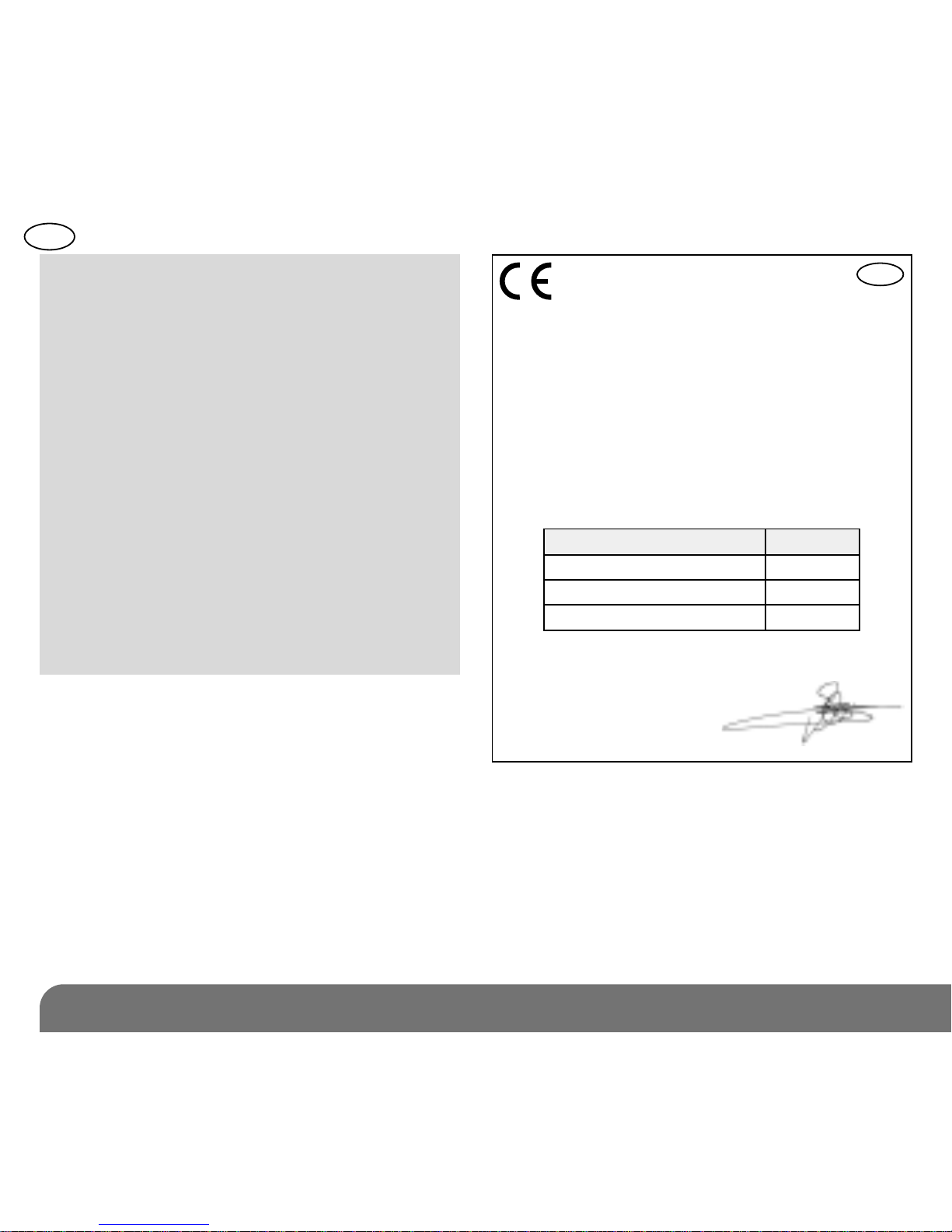
3. D fault configuration
The external universal transmitter is
factory-configured for use with terminal
block n° 1.
If this default configuration is suitable
for the application intended, programme
the transmitter to be recognised by the
control panel.
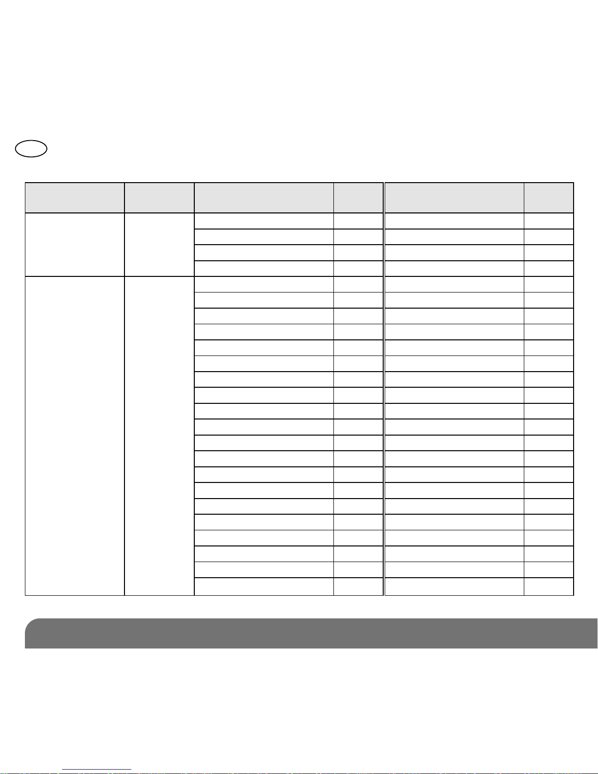
By default: intrusion detection
application on terminal block n° 1
• type of external sensor: NC (default
parameter value = 7),
• detector type: detector not protecting an
entrance to the home (default parameter
value = 1),
• 90 sec. inhibition after each detection:
inhibition enabled (default parameter
value = 2),
• alarm level: triggering on intrusion (default
parameter value = 1).
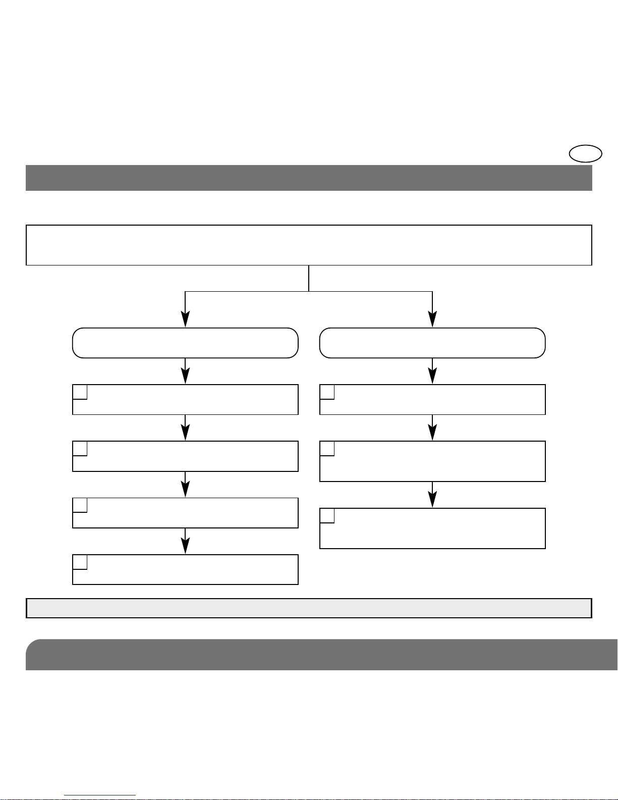
4. Appr ntissag
The external universal transmitter is
programmed so that a loop is recognised
by the control panel. According to the
application, each loop will be identified
either as a detector or as a control unit loop.
1. To programme the external universal
transmitter, the control panel must be
in installation mode. If it is not, ask the
user to press the following sequence on
the control panel keypad:
then:
IMPORTANT: in all other cases in which
terminal block n° 1 is used, or when a
technical probe needs to be connected, the
terminal block must first be configured
before being programmed on the control
panel. In this case refer to the Advanced
configuration operations chapter.
IMPORTANT: the control panel indicates
there is an error by emitting 3 short beeps.
When this happens programming should be
carried out again from the start.
IMPORTANT: during recognition program -
ming, the product to be programmed for use
with the control panel does not need to be
placed next to it. In fact, we recommend you
place the product at a short distance from
the control panel (at least 2 meters away).
master code
engineer installer code
138
GB
2. Carry out the programming sequence described below:
1. Press *then #
on the control panel
keypad to move to
programming mode
2. Press & hold
the “Test”
button until
the control
panel
responds (1)
5. The control
panel confirms
programming by
issuing a voice
message
(1) • For a technical detector:
“Technical detector X”.
• For a technical detector:
“Fire detector X”.
With these 2 applications,
there are no steps 3, 4 and 5.
or (depending on configuration)
detector
control unit
)))
10 sec. max.
2. Press & hold the
“Test” button until the
control panel responds
3. The control panel
confirms programming
by issuing a voice
message
10 sec. max.
then
3. The control panel
waits for a group
to be chosen from
1 to 8*. Press the
corresponding digits
on the control panel
keypad to choose
the group
4. The control panel waits for
the time delay to be chosen:
0: immediate,
1: delayed,
2: combined.
Press “0” or “1” on the
control panel keypad to
choose the
to *to
“group?” “time del y?”“detector X”
)))
“beep, remote control X”
“beep, detector X,
group Y, immedi te
(or del yed
or combined)”
* according to the model of the control panel.
139
GB
5.1 How is a loop configured?
Choose whether the loop is used for a detector
or a system control type application
Detector type application
or
System control type application
Choose the sensor type
1Choose the contact type
1
Choose the detector type
2Choose the order sent
when the loop is activated
2
90 sec. inhibition or not?
3
Choose the order sent
when the loop is de-activated
3
Choose the alarm level
4
5. Advanc d configuration op rations
IMPORTANT: configuration is essential prior to programming on the control panel.
140
GB
5.2 Configurations for a system control type application
Configuration type Parameter Configuration options Parameter
no. value
1/ Type of 1 NO monostable command 2
external NC monostable command 3
contact(s) NO bistable command 4
NC bistable command 5
2/ Order sent when 2 No order sent 1
loop activated Total OFF 21
(for a monostable Alarm (PA) 22
or bistable Total ARM D 23
command) Silent alarm 24
Armed Partial 1 25
and/or Armed Partial 2 27
Fire alarm 32
3/ Order sent when or Presence mode (stay) 33
loop de-activated Bell (chime) 38
(for a bistable 3 Audible signal 42
command) OFF light 52
ON light 54
System status 129
OFF Group 1 131
OFF Group 2 133
OFF Group 12 135
OFF Group 3 137
OFF Group 13 139
OFF Group 2 3 141
Configuration options Parameter
(cont.) value
OFF Group 12 3 143
OFF Group 4 145
OFF Group 1 4 147
OFF Group 2 4 149
OFF Group 1 2 4 151
OFF Group 3 4 153
OFF Group 1 3 4 155
OFF Group 2 3 4 157
OFF Group 1 2 3 4 159
Armed Group 1 163
Armed Group 2 165
Armed Group 1 2 167
Armed Group 3 169
Armed Group 1 3 171
Armed Group 2 3 173
Armed Group 1 2 3 175
Armed Group 4 177
Armed Group 1 4 179
Armed Group 2 4 181
Armed Group 1 2 4 183
Armed Group 3 4 185
Armed Group 1 3 4 187
Armed Group 2 3 4 189
Armed Group 1 2 3 4 191
141
GB
5.3 Configurations for a detector type application (*) default parameter settings
Configuration Parameter Configuration options Parameter Application
type no. value
1/ Type 1 Sensor without entrance NO 6 Applications other than door and window
of external contact supervision detectors in the home
sensor(s) Sensor without entrance NC 7(*) Applications other than door and window
contact supervision detectors in the home
Sensor with entrance NO contact supervision
8 Door and window detector in the home
Sensor with entrance NC contact supervision
9 Door and window detector in the home
Roller blind/shutter sensor 12 Roller blind/shutter detector
Technical probe 13 Household damage detection
2/ Type 2 Detector not protecting an entrance 1(*) Motion detector
of detector to the home ate/side door opening detector
lassbreak detector
Shock contact
Pressure mat
Infrared barrier
Detector protecting an entrance 2 Door and window detector
to the home
Roller blind/shutter detector 3 Roller blind/shutter detector
Fire detector 5 Fire detector
Technical detector 6 SONIN Daitem flood detector
SONCS Daitem mains power failure detector
SONPC Daitem freezer breakdown detector
SONHG Daitem freeze detector
3/ 90 sec. 3 Disabled 1 No inhibition
inhibition Enabled 2(*)
90 sec. detector inhibition after 1st transmission
4/ Alarm level 4 Intrusion 1(*) Alarm level managed by the control panel
Prealert 2
Deterrence 3
Warning 4
142
GB
5.4 To be filled in according to the application(s) to be performed
Please complete
Configuration sequence
Application Parameter n° Parameter value
1
2
3
4
LED indic tor
l mp OFF
LED indic tor
l mp ON
sequence
pprox.
5 sec. pprox. 10 sec. pprox.
2 sec.
pprox. 10 sec.
To start the
sequence
press & hold
the key until
the L D
indicator lamp
goes out.
Press the key
as many times
as the required
parameter
number.
Press & hold
the key until
the L D
indicator
lamp
temporarily
goes out.
Press the key as many
times as the required
parameter value.
(*) Wait one second
between digits
To end the
sequence
press & hold
the key until
the L D
indicator lamp
goes out.
L D
indicator
lamp
remains ON
=
configuration
programmed
1
sec. 1
sec.
(*) (*)
1st
digit
2nd
digit
3rd
digit
{
{
143
GB
Configuration example: configuring the universal transmitter for a technical detector
application (see table on page 141).
Checking configuration: check configuration by selecting the parameter number and
checking the number of corresponding flashes.
Start Press once
to select the
parameter
number
Press once
to confirm
selection
Press once then
3 times to select
the parameter
value (1 3)
End
1 1 3 pprox.
2 sec.
1 sec.
Press once
to select the
parameter
number
Press once
to confirm
selection
EndStart The configuration
1 3 is confirmed
by 1 then 3 flashes
1 31 1 s.
144
GB
6.1 Connection terminal blocks
Terminal blocks n° 1 and n°2 each have 3 terminals.
6. Conn ction
IMPORTANT: disconnect
the battery before
connecting the terminal
blocks.
NO / NC
COM
AT
V+
COM
SENSOR
Terminal block n° 1:
standard connection
Terminal block n° 2:
special connection
with polarising
slot to limit risk
of pole reversal
145
GB
6.2 Connecting several types of external contact
Anti-tamper loop
5 series contacts max.
Max. loop length: 10 m
{
5 series contacts max.
Unlimited
number
of
contacts
{
AT
COM
NO/NC
AT
COM
NO/NC
AT
COM
NO/NC
IMPORTANT
• Anti-tamper loops must be connected before the lithium battery is connected.
• The loop is then automatically recognised by the control panel when the lithium battery
is connected.
• Series-wired NC contacts:
- surface or flush-mounted normally
closed contacts,
- glassbreak sensor (piezo-electric),
- shock sensor,
- other non-specific sensors.
• Series-wired anti-tamper NC contacts:
surface or flush-mounted normally
closed contacts with anti-tamper
protection
• Parallel-wired NO contacts:
pressure mat.
{
146
GB
7.1 Fixing the external universal transmitter
4
screws
1 m mini
7. Installation
IMPORTANT
• Make sure there is a
distance of at least
2 meters between each
product, except between
two detectors.
• The transmitter should be
mounted the right way
round to guarantee its
degrees of mechanical
protection.
The transmitter should be
placed (see drawing):
• preferably on the frame of
the entrance to be
protected at least 1 m
above ground level,
• far away from all sources
of interference (electricity
meters, metal frames,
etc.).
Fixing method:
1. position the casing
with the cable gland
facing downwards,
2. fix the base to the wall
via the 4 fixing points
using screws suitable
for wall fixing.
Flush or surface-mounted encapsulated
cable normally closed contact
• NC loop with anti-tamper protection
against loop cutting:
- yellow and red wire: anti-tamper loop,
- green and blue wire: detection loop.
• NC loop without anti-tamper protection
against loop cutting:
• Surface mounting (NC): contact and
magnet to be screw-fixed and aligned
(using spacers if necessary)
• Flush-mounting:
- drill a hole in the doorframe and door
with an 8 mm diameter and 30 mm
deep.
- check that the contact and magnet are
opposite each other,
- drill a hole in the frame for the wire to
pass through.
147
GB
yellow
red
green
blue
AT
COM
NO/NC
black
red
AT
COM
NO/NC
7.2 Fixing and connecting the external contact(s)
148
GB
Normally closed ground contact
Surface-mounted contact Magnet position
Surface-mounted screw contact
Wide gap normally closed contact
Cover
Contact
Base
screw-
fixed to
doorframe
base
screw-fixed
to door
magnet
contact
magnet
Possible magnet
positions Incorrect magnet
positions
Magnet to be
screw-fixed to
door Contact
to be screw-
fixed to
doorframe
Cover
5 mm max.
shims
5 mm max.
Contact to be
screw-fixed to
doorframe Magnet
to be screw-
fixed to door
60 mm max.
Sensor for roller blind/shutter
Flush-mounted contact
Doorframe
Door
(lock side)
Magnet to be
screw-fixed
to door Contact
to be screw-fixed
to doorframe
60 mm max.
When a roller blind/shutter is connected, the
loop no longer has anti-tamper protection.
green
grey
red
AT
COM
NO/NC
149
GB
ach probe is connected to the external
universal transmitter by a flat connecting
cable (1.2 m long). The cable must be
pulled taut when each probe is fixed.
The cable is fitted with a connector that
acts as a polarising slot to facilitate
probe/transmitter connection.
FLOOD PROBE
¿Ground. ¡Metal plate. ¬Screw.
√Dowel. ƒSkirting board. ≈Wall.
∆Probe. «Magnet.
7.3 Fixing the technical probes
2 cm
Ã
Å
Â
ÀÁ
À
ÁÂ
Ç
Á
Æ
Ä
Ã
2 mm
2 mm
Depending on the customer’s needs the
probe can be positioned vertically or
horizontally on the ground to detect a
minimum water level of 2 mm.
The vertical position facilitates detection of
a higher water level (probe raised up from
the ground).
However it is positioned, the metal plate
supplied should be fixed to the support
and the probe flattened up against it. The
probe will be held in place by its magnet.
• Mark the metal plate fixing point
(according to the chosen detection
height) on the skirting board (vertical
fixing) or on the ground (horizontal fixing).
150
GB
For vertically-fixed probes, the metal plate
fixing hole must be placed high up.
• To detect a water level of 2 mm, the
bottom of the plate must be fixed 1 to 2
cm from the ground.
• To detect a water level above 2 mm, raise
the metal plate to the required height.
• Fix the metal plate using a suitable fixing
screw.
• Position the magnetic probe on the metal
plate.
Note: the probe can be removed to
simplify maintenance. We recommend you
clean it regularly to avoid dust from building
up between the probe and the ground.
Á
À
Ä
Â
Ã
FREEZER BREAKDOWN PROBE
¿Probe. ¡Connecting cable. ¬Bushing.
√Bushing groove. ƒFreezer seals.
• Open the freezer and place the probe
among the frozen food.
• The bushing supplied with the
accessories can be used to limit the risk
of cold loss.
• Slide the cable in the bushing groove and
stick the bushing to the freezer seal.

Other manuals for 230-21X

1

Other DAITEM Transmitter manuals

DAITEM 221-21 Series User manual

DAITEM

DAITEM 221-21 Series User manual

DAITEM 230-21X User manual

DAITEM

DAITEM 230-21X User manual

DAITEM DP8000 Series User manual

DAITEM

DAITEM DP8000 Series User manual

Popular Transmitter manuals by other brands

Bacharach MGS 550 user manual

Bacharach

Bacharach MGS 550 user manual

Weidmüller STG operating instructions

Weidmüller

Weidmüller STG operating instructions

Siemens SITRANS L Series Compact operating instructions

Siemens

Siemens SITRANS L Series Compact operating instructions

Sony TMR-PJ1 operating instructions

Sony

Sony TMR-PJ1 operating instructions

Nice ON1FM instructions

Nice

Nice ON1FM instructions

CMOSTEK CMT2150A manual

CMOSTEK

CMOSTEK CMT2150A manual

Linear Multi-Code 3022 quick guide

Linear

Linear Multi-Code 3022 quick guide

Technalogix TAUD-1000 Operation manual

Technalogix

Technalogix TAUD-1000 Operation manual

Macurco TracXP TXP-WTA instruction manual

Macurco

Macurco TracXP TXP-WTA instruction manual

COMECO TRA1 Operation manual

COMECO

COMECO TRA1 Operation manual

Star Meter KPE 9039G installation instructions

Star Meter

Star Meter KPE 9039G installation instructions

Analog Devices AN-826 Application note

Analog Devices

Analog Devices AN-826 Application note

Teledyne Analytical Instruments INSTA TRANS-XD operating instructions

Teledyne Analytical Instruments

Teledyne Analytical Instruments INSTA TRANS-XD operating instructions

KROHNE OPTIWAVE X400 Supplementary instructions

KROHNE

KROHNE OPTIWAVE X400 Supplementary instructions

RKI Instruments M2 Operator's manual

RKI Instruments

RKI Instruments M2 Operator's manual

FOXEER VTX Reaper Infinity 5W manual

FOXEER

FOXEER VTX Reaper Infinity 5W manual

enika P8 T 2C I quick start guide

enika

enika P8 T 2C I quick start guide

Audiovox ACA300 installation manual

Audiovox

Audiovox ACA300 installation manual

manuals.online logo
manuals.online logoBrands
  • About & Mission
  • Contact us
  • Privacy Policy
  • Terms and Conditions

Copyright 2025 Manuals.Online. All Rights Reserved.